C o n s t r u c t i o n T e c h n o l o g y U p d a t e N o . 5 5
Wind Effects on Roofs
Wind damage is the reason for many roofing insurance claims but little is known about the performance in wind of the SPRs often installed on low-slope commercial and industrial buildings. However, it is known that SPRs react differently to wind effects than conventional built-up roofs.
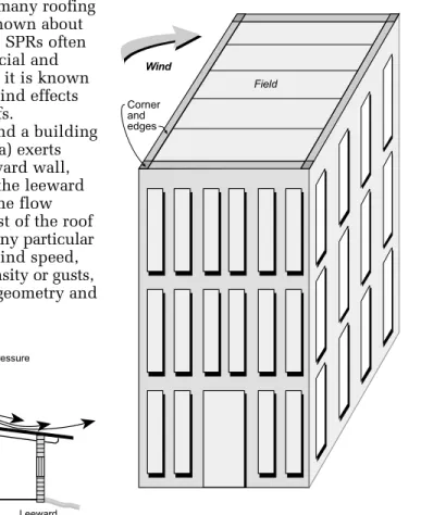
Wind passing over and around a building with a low-slope roof (Figure 1a) exerts positive pressure on the windward wall, negative pressure (suction) on the leeward wall and the walls parallel to the flow direction, and suction over most of the roof area. The suction generated at any particular roof location depends on the wind speed, wind direction, turbulence intensity or gusts, building topography, building geometry and
by A. Baskaran
Single-ply roofs (SPRs) behave differently than built-up roofs and a simple
test method is needed to ensure that they perform well under dynamic wind
conditions. This Update describes a new test protocol developed by an
industry-supported consortium project led by NRC’s Institute for Research
in Construction.
Dynamic Wind Testing of
Commercial Roofing Systems
Figure 1a.Wind-induced suction over a roof
Figure 1b.Commercial roofs, with their almost-flat profiles and low parapets, can experience high local suction pressures along the roof perimeter.
2
architectural features, and varies with time. Commercial roofs, with their almost-flat profiles and low parapets, are likely to experience high local suction pressures along the roof perimeter (Figure 1b).
Waterproof membranes are attached to the structural roof deck using fasteners (Figure 2). The attachment locations are then overlapped with another membrane sheet and the upper and lower sheets seamed together. Wind-induced suction repeatedly lifts the membrane between the attach-ments and causes membrane elongation and billowing. The magnitude of the wind-induced suction and the membrane’s elastic properties determine the extent of billowing.
Each roof component con-tributes resistance to the wind uplift force as illustrated by a force-resistance link diagram (Figure 3). All resistance links must remain connected for the roofing system to be durable and remain in place. Failure occurs when the wind uplift force is greater than the resistance of any one of these links. For example, the roof
assembly is considered to have failed when a fastener (link 4) pulls out from the deck even though the membrane and its seams are in good condition. Similarly, failure is
considered to have occurred when a seam (link 2) opens under gusting wind while other components remain intact. Testing and Certification of SPR Roofs
When designing a new roof, the designer consults a building code to determine the design wind pressure for the geographic location and selects a roofing system and details (such as fastener spacing) appropriate
for the local climatic wind conditions. To establish relia-bility, manufacturers of SPR systems test samples in accor-dance with standard methods to certify the systems will be able to withstand design wind loads; however, existing test methods have limitations.
North American Test Methods Existing certification standards used in North America to assess wind uplift ratings of SPR systems include those issued by Factory Mutual (FM)5and Underwriters’ Laboratories.7 Although easy to apply, these standards were developed for built-up roofing and do not simulate the dynamic wind conditions that generally cause mechanically fastened SPR roofs to fail.
European Test Methods The common European testing method (European Union of Agrément – UEAtc)4simulates actual wind conditions better than North American tests and, as a result, produces better estimates of actual wind uplift resistance of roofs. It uses a pressure load cycle based on meteorological data to simulate dynamic wind loading and accounts for size and edge effects, but the procedure is very time-consuming. For example, one UEAtc cycle with 1415 gusts takes nearly 3 hours to complete, and it can take as long as 50 hours for a full investigation.
Figure 2.Wind effects on single-ply mechanically attached roof assemblies
Figure 3.Force-resistance link diagram of single-ply roofs
The typical mean wind pressure distribu-tions for both normal and oblique winds are shown in Figure 5. Wind-induced pressures are negative (suction) and higher near the edges and corners than they are at the field of the roof. The tests showed that EPDM experiences a higher mean pressure than PVC for both normal and oblique wind conditions.
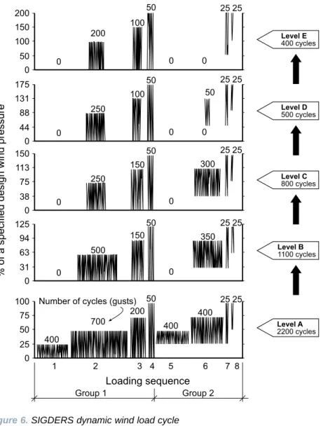
Based on the wind tunnel results, a review of existing standards, and computer simula-tions, and using IRC’s Dynamic Roofing Facility (DRF), IRC researchers devised a test loading procedure that allows a roofing system to be tested at any design wind pressure. This procedure,3represented in Figure 6, includes eight loading sequences
in which a roof system is subjected to simulated gusts. The loading sequences are grouped into five different levels (Levels A to E).
There are two groups of cycles at each test level: Group 1 cycles, which simulate wind-induced
suction over a roof assembly,
and Group 2 cycles, which simulate the effects of exterior
wind fluctuations combined
with a constant interior pressure on a building. Each group consists of four loading sequences in which the pressure level alternates between zero and a fixed pressure. Allowable internal pressure variations are explicitly specified in recent North American wind standards and the National SIGDERS Test Protocol
To develop a more effective test method for certifying mechanically fastened SPR systems, IRC formed a consortium called SIGDERS (Special Interest Group for Dynamic Evaluation of Roofing Systems).
The first phase of the research was the full-scale wind tunnel testing of SPR systems with PVC and non-reinforced EPDM membranes (Figure 4). Both steady and gusty wind conditions were simulated and pressures measured at a number of locations to observe the fluctuations experienced by an SPR.
Figure 5.Wind pressure distributions measured from the wind
Figure 4.Wind tunnel model
The goal of the SIGDERS project was to develop a test method that would: • mimic real wind effects
• achieve failure modes observed under real conditions
• be easier to apply in the laboratory than existing tests
• allow for variation in roof design • produce results quickly
• meet most North American building code requirements
Building Code (NBC),1,6and are taken into account in the SIGDERS test protocol.
Each loading sequence is performed at a pressure that is a percentage of the design wind pressure stipulated by applicable building codes and standards for a given type of building and a particular location, starting with lower pressures and increasing gradually with each level. For example, the Level A tests include one sequence of 400 cycles (gusts) at 25% of the design wind pressure, another sequence of 700 cycles at 50% of the design wind pressure, and so on, for a combined total of 2,200 cycles.
To evaluate the ultimate strength of the roofing system, testing begins at Level A. If all the resistance links (Figure 3) remain connected, the roof is considered to have “passed” and obtains a rating. Testing then proceeds to the next level, where the pressure is increased (see Figure 6).
Comparison of Test Protocols
IRC’s Dynamic Roofing Facility, used in the development of the SIGDERS loading cycle, permitted a comparison of the results obtained using the SIGDERS loading cycle with the results from both the UEAtc and FM pro-cedures. Table 1 compares the test parameters and attributes of the FM,5UEAtc4and SIGDERS2 test protocols. As shown in the table, the SIGDERS dynamic test protocol for SPRs produces failure modes similar to UEAtc, but has several additional benefits, such as the consideration of membrane flutter and the completion of tests in much less time.
Benefits of the SIGDERS Test Protocol
Support for the SIGDERS project by the roofing industry reflected a genuine need for new methods to ensure that roofing systems can perform in high, gusting winds. The new test protocol overcomes the limita-tions of current test methods. It has been submitted to the Canadian Standards Association for consideration as a national standard for Canada. It is likely that other jurisdictions in North America will benefit from this research as well. The test protocol will provide manufacturers with assurances that their products have been effectively tested and building owners with roofs that have longer service lives.
4 Construction Technology Update No. 55
Recently, SIGDERS released a report2 describing the procedures for using the dynamic load cycle and installing the roof assembly, and reporting the test data. Once the SIGDERS test protocol becomes a national standard, manufacturers will be able to have their products tested, and after certifications are obtained, designers will be able to specify SPRs that meet the SIGDERS test requirements.
Summary
Developed by IRC in cooperation with manufacturers, building owners and roofing associations, SIGDERS is a new test protocol for easily evaluating the ultimate strength of flexible membrane roofing systems under dynamic wind conditions. Once implemented as a national standard, the protocol will contribute to improved predictability and service life of these roofing systems.
References
1. ASCE. “Minimum Design Loads for Buildings and Other Structures.” ASCE Standard 7–98, American Society of Civil Engineers, Reston, VA, 1997, p. 13. 2. Baskaran, A. and Nabhan, F. “Standard
Test Method for the Dynamic Wind Uplift Resistance of Mechanically Attached Membrane Roofing Systems,” Internal Report IRC-IR 699, National Research Council of Canada, Institute for Research in Construction, Ottawa, 2000. 3. Baskaran, A. and Chen, Y. “Wind Load
Cycle Development for Evaluating Mechanically Attached Single-Ply Roofs,” Journal of Wind Engineering and Industrial Aerodynamics, Vol. 77-78, 1998, pp. 83-96.
4. Baskaran, A. and Lei, W. “A New Facility for Dynamic Wind Performance
Evaluation of Roofing Systems.” Proceedings of the Fourth International Symposium on Roofing Technology, NRCA/NIST, Washington, DC, 1997, pp. 168-179.
Table 1. Features of the FM, UEAtc and SIGDERS test methods
Parameter FM UEAtc SIGDERS
Source data N/A Wind climatic Roof pressure
data time histories
Relationship with wind speed Yes No Yes
Relationship with applicable
codes and standards No No Yes
Internal pressure No No Yes
High-frequency fluctuations No Yes No
Membrane flutter No No Yes
Testing time* < 0.5 hours 55 hours 5 hours
Maximum number of gusts N/A No 5000
Low-intensity gusts N/A 71% of test cycles 18%
(<40% of test pressure)
Medium-intensity gusts N/A 28% of test cycles 68% (40-75% of test pressure)
High-intensity gusts N/A 1% of test cycles 14%
(>75% of test pressure)
Correction for temperature No Yes No
Correction for specimen size No Yes Yes
End product Static Fastener Dynamic
evaluation design load evaluation *Varies according to roofing system
“Construction Technology Updates” is a series of technical articles containing practical information distilled from recent construction research.
For more information, contact Institute for Research in Construction, National Research Council of Canada, Ottawa K1A 0R6
Telephone: (613) 993-2607; Facsimile: (613) 952-7673; Internet: http://www.nrc.ca/irc © 2002
National Research Council of Canada November 2002
ISSN 1206-1220 5. Factory Mutual Research, Approval
Standard: Class I Roof Covers (4470), April 1986.
6. National Building Code of Canada 1995, Canadian Commission on Building and Fire Codes, National Research Council of Canada, Ottawa. Also structural commentaries (Part 4).
7. Underwriters’ Laboratories Inc., Standard for Uplift Pressure of Roof Assemblies (UL 560), 1996.
Dr. A. Baskaran is a senior researcher in the
Building Envelope and Structure Program of the National Research Council’s Institute for Research in Construction.
SIGDERS consortium members Manufacturers
Atlas Roofing Corporation Canadian General Tower Ltd. Carlisle SynTec Incorporated GAF Materials Corporation GenFlex Roofing Systems
Firestone Building Products Company IKO Industries Ltd.
Johns Manville Sarnafil
Soprema Canada
Stevens Roofing Systems Vicwest Steel
Building Owners
Canada Post Corporation Department of National Defence
Public Works and Government Services Canada
Associations
Canadian Roofing Contractors’ Association
Canadian Sheet Steel Building Institute Industrial Risk Insurers
National Roofing Contractors’ Association