SIM UNIVERSITY
SCHOOL OF SCIENCE AND TECHNOLOGY
INTEGRATED DATA RETRIEVAL SYSTEM
STUDENT
: PRAVEEN KURIAN (PI: B0704606)
SUPERVISOR : MR. KUMBAR SHANKARAPPA
PROJECT CODE : JAN2011/ENG/069
A project report submitted to SIM University
in partial fulfilment of the requirements for the degree of
Bachelor of Electronics Engineering
ABSTRACT
Integrated Data Retrieval System is a mission-critical, user friendly and powerful
software solution built based on an imperative objective of retrieving and analyzing the
test data and histories for the semiconductor company that I am currently working for.
It helps Quality & Reliability Assurance (QRA) team with readily available results and
data for analysis and further follow up for manufacturing improvements in future.
This report consists of 7 chapters. Chapter 1 describes the objectives and approaches of
this project in details. Chapter 2 emphasizes on the Literature Review of IDRS and the
software tools used for developing the system. Chapter 3 explains software
development process with Unified Model Language (UML) diagrams and database
design diagrams.
Chapter 4 shows the system testing and results of the developed IDRS system and also
displays the functions and flows of the system. Chapter 5 discusses on the project
management with a Gantt chart. Chapter 6 is the conclusion and recommendations
which explains the achieved objectives and recommendations for future enhancements.
Lastly, chapter 7 is the critical review and reflection which discusses some of the
problems that were encountered during the project and their solutions. Concurrently, it
also discusses about the learning and reflections from this project.
ACKNOWLEDGEMENT
I would like to express my deep gratitude to SIM University
for providing an
astounding opportunity and a friendly atmosphere in their organization for the
development of this Integrated Data Retrieval System for my current Semiconductor
Company.
I am especially grateful to my Project Supervisor Mr.Kumbar Shankarappa
for his
invaluable superintendence, sustained and invaluable help and advices to accomplish
the project successfully.
I am thankful to my friends who gave their constant encouragement and support in all
the phases of my project work.
I am highly grateful to my beloved parents and colleagues for their valuable support
throughout the course of the project. Thanks to all whoever supported me by providing
valuable advises and comments.
TABLE OF CONTENTS
ABSTRACT...i
ACKNOWLEDGEMENT...iii
TABLE OF CONTENTS...iv
LIST OF FIGURES...v
CHAPTER 1: INTRODUCTION ... ....1
1.1 Introduction ... 1
1.2 Objectives ... 1
1.3 Overall Objectives ... 1
1.4 Scope deliverables and boundaries ... 3
1.5 Proposed approach ... 3
1.5.1 Waterfall model...4
1.5.2 Processes List...6
CHAPTER 2: LITERATURE REVIEW ... 7
2.1 Background study ... 7
2.2 Motivation ... 8
2.3 Technology Selection ... 9
2.4 IDRS (Integrated Data Retrieval System) Terminology ... ..10
2.5 Software Tools ... 10
2.5.1 .Net Framework...10
2.5.2 Visual Studio 2010...12
2.5.3 C Sharp...12
2.5.4 ASP .Net...12
2.5.5 Internet Information Services (IIS)...12
2.5.6 MS SQL Server 2008 R2...12
CHAPTER 3: SOFTWARE DEVELOPMENT ... 14
3.1 IDRS Software Overview ... 14
3.2 IDRS Front-end Flow Layout ... 15
3.3 Client server architecture for IDRS Desktop application ... 17
3.4 Three tier Architecture for web application ... 17
3.5 SMS Gateway Integration ... 17
3.6 Use Cases Diagram ... 18
3.7 Use cases of Integrated Data Retrieval System ... 19
3.8 Class Diagrams of IDRS Desktop application ... 21
3.9 Class Diagram of IDRS Web application ... 22
3.10 Database Design ... 23
3.11 Sequence Diagram for IDRS ... 24
3.11.1 Login Use Case...24
3.11.2 Add new RMA use case...25
3.11.3 Add new SLT use case...25
3.11.4 Add new SMT use case...26
3.11.5 Add new Visual data...27
3.11.6 Search module details...27
3.11.7 Messaging service...28
3.12 Overview of software components developed ... ..28
CHAPTER 4: TESTING AND RESULTS ... 29
4.1 Testing Objectives ... 29
4.2 Software Testing Methods ... 30
4.2.1 White - Box Testing...30
4.2.2 Black - Box Testing...30
4.3 Software Testing Strategy ... 30
4.3.1 Unit Testing...30
4.3.2 Integration Testing...31
4.3.3 Validation Testing...31
4.3.4 System Testing...31
4.4 Test Cases for IDRS Desktop Application ... 31
4.4.2. Add a new user Test...33
4.4.3. Search module details by lot ID...35
4.4.4. Add RMA data...36
4.4.5. Add SMT details...39
4.4.6 Add SLT details...40
4.4.7 Add visual data...43
4.5 Web application ... 44
4.6 Messaging service ... 46
CHAPTER 5: PROJECT MANAGEMENT ... 54
5.1 Project Planning ... 54
5.2 Project Initiation ... 54
5.3 Design and Development ... 54
5.4 Testing & Troubleshooting ... 55
5.5 Project Completion ... 55
5.6 Effort Calculation ... 55
5.7 Resources Required ... 59
CHAPTER 6: CONCLUSION AND RECOMMENDATIONS ... 60
6.1 Conclusion ... 60
6.2 Recommendations ... 60
6.2.1 Desktop application...60
6.2.2 Web application...60
6.2.3 Message Gateway...61
CHAPTER 7: CRITICAL REVIEW AND REFLECTIONS ... 62
7.1 Problem 1: Inexperience in Project Management. ... 62
7.2 Problem 2: Inexperience in software tools ... 62
7.3 Reflections ... 63
APPENDICES ... 65
APPENDIX A: IDRS Windows application source code ... 65
APPENDIX B: IDRS Web application source code ... 114
APPENDIX C: Messaging Service source code ... 121
APPENDIX D: Meeting Logs ... 133
LIST OF FIGURES
1.1 Overview of IDRS system Architecture
2
1.2 Waterfall Model
4
3.1 Overview of IDRS Software Modules
14
3.2 Front-End Flow Layout of IDRS
15
3.3 Client-Server Architecture style
16
3.4 Three-tier Architecture style
17
3.5 Use cases diagram of IDRS
18
3.6 Overall class diagram of IDRS Client application
21
3.7 Overall class diagram of IDRS Web application
22
3.8 IDRS Database design
23
3.9 Login sequence diagram
24
3.10 Add new RMA sequence diagram
25
3.11 Add new SLT sequence diagram
25
3.12 Add new SMT sequence diagram
26
3.13 Add new Visual Data sequence diagram
27
3.14 Search Module Details sequence diagram
27
3.15 Messaging Service sequence diagram
28
4.1 Login Page
32
4.2 Overview Page
33
4.3 Add User
34
4.4 Missing fields
34
4.5 Search module details
35
4.6 New RMA
37
4.7 RMA Error Message 1
37
4.8 RMA Error Message 2
38
4.9 Save RMA
38
4.10 SMT Error
39
4.11 Add SMT
40
4.12 Add SLT
41
4.13 SLT Errors
42
4.14 Visual data
43
4.15 Save Visual data
43
4.16 Overview page
44
4.17 Search page
45
4.18 Module Details page
46
4.19 SMS Help
47
4.20 SMS Login validation
48
4.21 SMS RMA Details
49
4.22 SMS SMT Result
50
4.23 SMS SLT Result
51
4.24 SMS Visual Test
52
4.25 SMS Comment Function
53
5.1: Gantt chart – Project Initiation & Design and Development Phase
57
LIST OF TABLES
1.1 Processes List
6
1.2 System Components
7
3.1 Main Software components created for Windows Application
29
3.2 Main Software components created for Web Application
29
3.3 Other software components
29
4.1: Unit and Test Validation for Login
33
4.2: Unit and Test Validation for „Add new user‟
35
4.3: Unit and Test Validation for Search function
36
4.4: Unit and Test Validation for „New RMA‟
39
4.5: Unit and Test Validation for „SMT‟
40
4.6: Unit and Test Validation for „SMT‟
42
4.7: Unit and Test Validation for Visual data
44
4.8: Unit and Test Validation for Search function in Web application
45
4.9: Unit and Test Validation for Search function in Messaging Service
46
5.1: Project tasks list
55
CHAPTER 1: INTRODUCTION
1.1 Introduction
Analysis of data and test results is the most tedious job for the engineers in any
semiconductor company simply due to the inaccessibility of the huge amount of data
available across different application systems at various servers. All these data would
need to be consolidated by a system on a single interface for a successful analysis which
will play an important role in further manufacturing improvements of the product in
future.
1.2 Objectives
The objective of the project is to develop a Web and Windows based Data Retrieving
System with integrated SMS gateway functionalities for my current semiconductor
manufacturing Company. This system is developed based on an imperative objective of
entering, retrieving and analyzing the customer-returned module details and test data for
the company.
This system helps the Quality & Reliability Assurance (QRA) team with readily
available results and data for analysis and further follow up for the future manufacturing
improvements.
1.3 Overall Objectives
Retrieving and analyzing of wafer lot histories, shipping histories & test results from
various servers is one of the mind-numbing jobs for the engineers in my company as any
other semiconductor manufacturing companies.
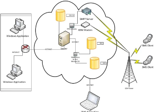
Integrated Data Retrieval System
(IDRS) is a mission critical system consisting of both Windows and Web based
applications with a single database and SMS integration that supports employees to
retrieve test data across the company. The QRA team in the company needs this data
whenever a failure is reported from any of its customers. It will then be very useful to
have an application that can orderly display out the history and test results of
semiconductor devices.
Figure 1.1: Overview of IDRS system Architecture
In this system, the following features should be implemented:
1) Windows and Web based applications for retrieving data from servers and databases
and to display it out in a graphical & user-friendly manner for analytical purposes.
2) A database for data storage to speed up the overall process by avoiding the real time
communication with multiple servers.
3) An integrated SMS gateway for anytime anywhere data retrieval from the system and
to provide updates to the system.
1.4 Scope deliverables and boundaries
The scope of the project is to develop a Windows as well as web-based Data
management system with SMS functionalities. This system consists of two main
components: a Windows based application used for managing all the product details
including various test results and a web-based application for employees to get the
overview of the status of the pending modules through intranet. An anytime anywhere
reporting and data management functionality using SMS gateways is also implemented.
1.5 Proposed approach
Systems Development Life Cycle or Software Development Life Cycle is a process of
developing software with regards to the requirements through investigation, analysis,
design, implementation and maintenance. Many methodologies or SDLC models have
been created to manage the complex process of software development. They are:
Waterfall: a linear framework
Prototyping: an iterative framework
Incremental: a combined linear-iterative framework
Spiral: a combined linear-iterative framework
Rapid application development (RAD): an iterative framework
Extreme Programming
Waterfall method has been selected as the development methodology for this project as
it has the appropriate principles for IDRS development.
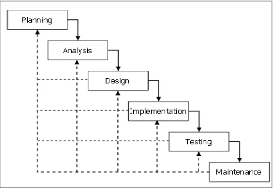
1.5.1 Waterfall model
Figure 1.2: Waterfall Model
Waterfall is the simplest and systematic software process model with a sequential or 'top
down' development approach in which the output of each stage becomes the input for the
next. This model has the following stages:
1.5.1.1
Project Planning
Project planning based on all the requirements is to be done at this phase. Both
the functionalities and constraints have to be gathered and as the requirements to
plan the project properly. A requirement Specification Document should be
created as a guideline for the next phase of the model.
1.5.1.2 System Analysis
Further analysis based on the end-user requirement has to be done in System
Analysis phase. It refines the functions and operation of the application to
accomplish the project goal impeccably.
1.5.1.3 System Design
Overall system architecture is developed during this phase using the requirements
gathered in the planning phase. The main components of the intended system including
programming language, architecture, platform, database, algorithms, interfaces and
many other details are established during Design phase.
1.5.1.4 Implementation
Coding and Testing are the key components in Implementation stage. Software program
is to be written and integrated based on the inputs from Design phase.
1.5.1.5 Testing
The implemented software module has to be tested in this phase after the final
integration for errors, bugs and interoperability.
1.5.1.6 Operations/ Maintenance
The performance of the fully developed and tested system will be monitored in this
phase to adapt accordingly with any changes after implementation.
1.5.2 Processes List
Table 1.1 Processes List
Process
Description
Output
Skill
Project
Initiation
-Research
-Map activities to Software
Life Cycle Model
-Project Plan
-Gantt Chart
- Initial Project
Proposal
- Project Plan
- Project Management
Requirement
-Define and Develop
Software Requirement
-Define Interface
Requirement
-Prioritize and Integrate
Software Requirements
Final Report
- Software
Engineering
Design
-Perform Architectural
Design
-Design Database
-Design Interface
-Perform Detailed Design
Final Report
- UML Design
- Database
normalization
- Database Design
- Software
Engineering
Implementation
-Create Test Data
-Create Source
-Plan Integration
-Perform Integration
- Final report
- Software
product
- Software
Engineering
- Application Server
- ASP .Net, MSSQL,
C#, Visual Studio
2010
Verification and
Validation
-Plan Testing
-Develop Test Requirements
--Execute the Tests
- Final report
- Software
CHAPTER 2: LITERATURE REVIEW
2.1 Background study
Data management and analysis are the critical requirements for the engineers in any
Semiconductor manufacturing company. Currently the data is hosted in several servers
and databases making it difficult for the users to retrieve them at the required time and
place. This inaccessibility makes the work process slow. For the case of my company,
the modules that are returned from the customers after failure detection are tested at
different testers for detailed analysis of the failure. Further analysis of those test results
located at different servers and databases is required at a single interface to conclude the
root cause of the failure.
In today‟s world of high competition where organizations are trying to meet their
customers‟ needs at the earliest and best possible ways, speed is very critical. Customers
have several choices in the industry. So, it is how well we meet the customer‟s need and
at the earliest that wins us the major customers. By having an application that compiles
and organizes all the necessary data, it makes the life of QRA engineers much easier and
allows them to serve their customers needs at a faster pace.
The System comprises of the following components:
System Components
Server
Client
Request Validation
Data Processing
Reporting
Web UI
Database Layer
User Authentication
SMS Gateway
Windows UI
2.2 Motivation
Strategic change is necessary for any organization to meet the needs of the fast moving
world. Software systems are the one handling and solving almost all the complex tasks
in any company nowadays and obviously the overall performance of the company or the
department will rely upon the performance of such systems. Here comes the need of
having an up to date software system with current technologies implemented.
These are some of the main features and benefits of Windows Systems compared to the
current system based on
Text-based interface (TUI) used in my company which
becomes the motivational factor to me to choose the project. They are:
Compatibility
o
The software is designed to operate on the existing infrastructure at my
semiconductor company. The application is designed to support
interoperability with existing databases in the company.
Scalability
o
The software‟s architecture is designed to support scalability at any point
of time. New capabilities can be added to the software without making
major changes to the underlying architecture.
Maintainability
o
The application will have a built in self update engine that can update
itself to newer versions whenever available.
Fault tolerance
o
The software will be resistant to and able to recover from component
failures at client pc.
Modularity
o
The software is designed with well-defined and independent components
that lead to better maintainability in the future.
Reusability
o
The software will be capable to add more features with slight changes.
Also web service allows calling from cross platforms that will help in the
future to easily port the client application to various different operating
systems varying from desktops to various mobile handhelds.
Reliability
o
The software will be able to perform all the required functions with least
errors and at higher speeds.
Security
o
The software will be hardened against to withstand hostile acts and
influences using higher standard encryptions.
Usability
o
The interface will be highly intuitive and graphical where the target
audience can analyze data in an effective manner.
Robustness
o
The software will be able to operate under stress or tolerate certain
unpredictable or invalid input. This consideration will also include the
minimum requirements for the client system, for e.g. The software will be
designed with resilience to low memory conditions
2.3 Technology Selection
The software design will be based on object oriented programming concept, where an
object contains encapsulated data and procedures grouped together to represent an
entity. An object oriented program is described by the interaction between these objects.
Object oriented design is the discipline of the objects and their interactions to solve a
problem that was identified and documented during object oriented analysis. Our
software will be based on the composite reuse principle that favours polymorphic
composition of objects over inheritance.
Our system will be deployed in a client-server architecture that enables roles and
responsibilities of a computing system to be distributed among several independent
computers that are known each other only through a network. This creates an additional
advantage of greater ease of maintenance. For example it is possible to replace, repair,
upgrade or even relocate the server while the clients remains both unaware and un
affected by the changes.
All data is stored on the servers that have better, security, access controls and resources
to guarantee that only those clients with appropriate permissions can access the data.
Since the data storage is centralized, updates to that data are far easier to administer. Our
system can function with multiple different clients with different capabilities with ease.
2.4 IDRS (Integrated Data Retrieval System) Terminology
These are some of the IDRS terminologies that will be used in this project.
1.
RMA
- Returned Module Authorization is a generic term which
represents a returned module from customer
2.
SMT
- Single Module Testing is type of bench top, electrical testing.
3.
SLT
- System Level Testing is another type of test on different
platforms.
4.
LOT ID
- A unique module Identification ID
5.
Visual
- Visual Test using Microscope
6.
Part number - Unique idenfier of a module design
7.
Serial number - Reference number for a module either by customer or
manufacturer
2.5 Software Tools
This section describes the software tools that this project is utilizing and the reasons to
use them.
2.5.1 .Net Framework
.Net Framework is a general software development platform which provides a
platform-independent framework that enables developers to quickly build, deploy, and manage
Web-based applications, smart client applications, and XML Web services applications
based on a Virtual Machine that offers independence to a programmer. Multiple
programming languages like C#, Visual Basic .Net and managed C++ can be used to
develop any software using this object-oriented programming (OOP) model.
Side-by-side execution of code and decentralized registration of components are the key benefits
of .Net. The platform-independence feature enables businesses to quickly integrate their
systems, information, and devices, thereby helping users collaborate and communicate
effectively.
This execution environment consists of two major components:
1. Common Language Runtime (CLR)
The common Language Runtime manages the intrinsic features like memory
management, code execution, thread execution, code safety verification, compilation
and other system services. The Runtime enforces the code access security and
robustness by implementing a type-and-code infrastructure called the common type
system (CTS). It will also enhance the performance, developer productivity and
memory management by using sophisticated technologies below:
Common Type System (CTS)
Common Language Specification (CLS)
Just-in-Time Compiler (JIT)
Virtual Execution System (VES)
2. Base Class Library (BCL)
All the functionalities for the developers are available in .Net framework through a Class
Library which has got the features like Windows Forms for GUI, ADO.Net for Database
access and ASP.Net for web development. This Class Library is a collection of reusable
types that tightly integrate with the common language runtime.
The framework's Base Class Library provides:
user interface
data access
database connectivity
cryptography
web application development
numeric algorithms
2.5.2 Visual Studio 2010
Microsoft Visual Studio is the Integrated Development Environment (IDE) used to
develop this project. It includes a code editor, an integrated debugger and other built in
tools like forms designer for building various applications and enhancing functionality.
It suits for the project because of the multi language support and other built in features
mentioned.
2.5.3 C Sharp
C# is a multi paradigm programming language developed by Microsoft intended to be a
simple, object oriented language for .Net framework. I had selected C#.Net because of
the rapid application development capabilities of .NET and also the visual tools
available. C# is the most advanced and latest programming language comparing to
VB.Net and lot of tutorials and samples are available for C# will make the development
much faster and easier.
2.5.4 ASP .Net
ASP .Net is an application framework developed by Microsoft for building web
applications, web services and web sites. It allows programmers to develop dynamic
applications using any .Net supported language which can be managed by Common
Language Runtime (CLR) in .Net framework.
2.5.5 Internet Information Services (IIS)
IIS is a web server application with essential extensions provided by Microsoft to use
with Windows Operating System which will play a vital role in most of the Microsoft
Server products. .NET based solutions can only be hosted on IIS and couldn‟t be hosted
on apache or Linux based environments. Since our web service is developed using .NET
technologies, IIS is the best option for the hosting.
2.5.6 MS SQL Server 2008 R2
SQL Server is a rational database server for storing and retrieving data requested by
software applications. It is developed by Microsoft intending to used with local as well
as network applications. Even though mySQL is widely popular and free to user, I had
selected MSSQL because our solution is fully based on windows and .NET, it will be
easy and faster to use a native compatible database for better manageability,
compatibility and scalability also easy to sync with multiple database if necessary.
Moreover MSSQL Express is free to use and perfectly suits our requirements.
2.5.7 MS Office
Microsoft Office Visio 2007: It simplified the process of drawing and designing UML
and database. With this tool, the developer can focus more on the design not on the
drawing instead.
Microsoft Excel 2007: Excel is used to generate the report of the details for a particular
module or the total pending modules.
CHAPTER 3: SOFTWARE DEVELOPMENT
3.1 IDRS Software Overview
Business Objects
Database access layer
Database
User Management
and
Administration
Returned Module
Authorization (RMA)
Test results
Reporting
SLT
SMT
VISUAL
ADO.NET
SQL Server
Application
Users
RMA
SLT
SMT
Visual Data
SMS
Gateways
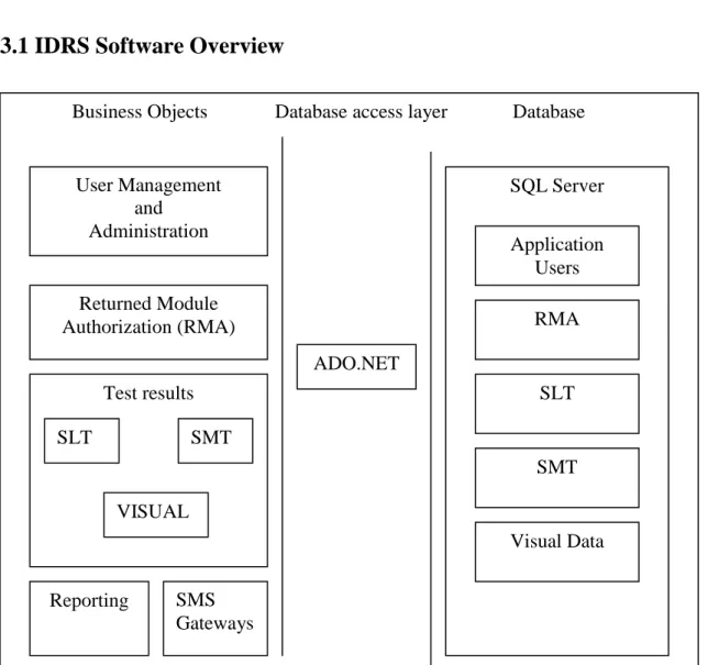
Figure 3.1: Overview of IDRS Software Modules
Figure 3.1 shows the overview of software components that are intended to be designed
in this project. The main modules in the business objects are user management and
administration, RMA, Test results and reporting modules. The data access layer is
managed by the ADO.NET library. Microsoft SQL Server 2008 R2 is used as database
management system (DBMS).
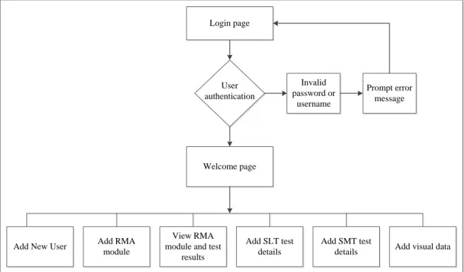
3.2 IDRS Front-end Flow Layout
Login page
User authentication
Welcome page
Add New User Add RMA module
View RMA module and test
results
Add SLT test details
Add SMT test
details Add visual data Invalid
password or username
Prompt error message
Figure 3.2: Front-End Flow Layout of IDRS
Figure 3.2 displays the front-end IDRS flow layout. Basically, the foremost page of this
system is the login page. There are three options in this page which are:
1.
registers for new user account,
2.
Login to the IDRS system.
After the user login to the system, they may utilize the functionalities of the system
pertaining to their access right role.
Welcome page can be accessed upon successful login and it will display out the status of
all the pending modules entered into the system by various users. Almost all the details
except the test results will be available on this page.
There are four buttons displayed on the main page; they are:
Overview
„Overview‟ button is to check the status of all the pending modules entered into the
system as explained above.
Search
All the details including test results of any particular module can be viewed by using
this function by entering the unique Lot ID assigned with every module. Test result
status is shown in
New Lot
A new RMA module lot can be created using this function by entering all the details
with a unique Lot ID.
Test Results
There are three types of tests can be added into our system related to any returned
module. They are:
i.
SMT (Single Module Test)
It is a kind of electrical testing with the help of a bench top tester. All the
information can be added and modified using this particular function.
ii.
SLT (System Level Test)
System Level Test details need to be added to the system using this
functionality.
iii.
Visual Test
All kinds of Visual defects found on the returned modules need to be updated
to the system with pictures. Two images can be saved to the system by
browsing them from the local drives.
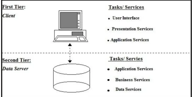
3.3 Client server architecture for IDRS Desktop application
Figure 3.3: Client- Server Architecture style
3.4 Three tier Architecture for web application
Figure 3.4: Three-tier Architecture style
3.5 SMS Gateway Integration
A highly scalable Messaging gateway is integrated with the system to enable truly
mobile cross platform mobile functionality. The messaging system is capable of
handling concurrent connections between multiple gateways consisting of GSM
modems as well SMPP connections. The system will automatically load balance
between multiple gateways using Round Robin.
SMS can be send at a speed of 12 SMS per second. Heavy traffic to the system can be
easily handled by adding SMPP connections which can handle 700 to 20,000 SMS per
second depending on the service provider.
3.6 Use Cases Diagram
Staff
Add a new user Add a new user Add a new user
Add RMA module
View RMA details
Add SLT details
Add SMT details
Add Visual data
Reporting Service
Messaging Service Admin
As described in Figure 3.3, there are two actual types of human users i.e. administrator
and staff. Admin will be able to perform any of the use cases and the user is only
restricted to modify anything related to user management.
3.7 Use cases of Integrated Data Retrieval System
3.7.1 Add a new user
This case allows the actor with administrative right to add a new user to the system. The
new user would have a default staff access control.
3.7.2 Add RMA module
RMA module in our system indicates any module returned by customer for failure
analysis. All the main details such as part number, serial number, customer name and
product family need to be added with each module to the system. This use case allows
user with either admin or staff access control to add new RMA module details.
3.7.3 View RMA details
All the details including Test results of any particular module can be retrieved using the
unique Lot ID assigned to the module. This use case allows user with either admin or
staff access control to view and modify RMA module details in particular by their LOT
ID.
3.7.4 Add SLT details
System Level Test details of a module can be captured to the system using this
functionality. This use case allows user with either admin or staff access control to add
System Level Test details.
3.7.5 Add SMT details
Basic electrical checking of a module is performed during Single module Test. This use
case allows user with either admin or staff access control to add Single Module Test
details.
3.7.6 Add visual data
Cosmetic damages found during visual test of a module need to be captured in the
system with images of those defecfts. This use case allows user with either admin or
staff access control to add visual Test details.
3.5.7 Reporting service
Reporting service allows user with either admin or staff access control to generate RMA
module details and test results from the corresponding page itself to an excel sheet.
3.7.8 Messaging service - An integrated SMS Gateway functionality has been added to
the system through which users can interact with the system using their mobile phones
by sending the queries and comments in a predefined format. The query formats are:
<username> <password> <action> <Lot ID>. Available actions are „RMA‟ for getting
module details, „VT” for visual test results, „SMT‟ for SMT results, “SLT” for retrieving
SLT results and “CMT‟ for making comments to any particular module in the system.
The comment will be displayed under the „SMS Comments‟ section in the overview
page after sending it to the number assigned to IDRS system.Messaging service allows
user with either admin or staff access control to view or update RMA module details and
test results through short messaging service (SMS) using any GSM enabled mobile
device.
3.8 Class Diagrams of IDRS Desktop application
Figure 3.6: Overall class diagram of IDRS Client application
Figure 3.4 shows the overall class diagram of IDRS Windows application. The fields
and methods used in each class are also shown in the figure.
3.9 Class Diagram of IDRS Web application
Figure 3.7: Overall class diagram of IDRS Web application
Figure 3.5 shows the overall class diagram of IDRS Web application. The fields and
methods used in each class are also shown in the figure.
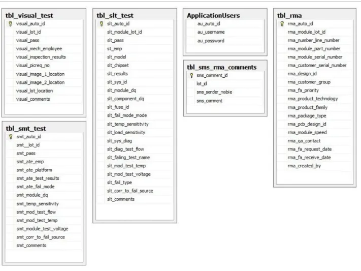
3.10 Database Design
3.11 Sequence Diagram for IDRS
Sequence diagram for the desktop and web interfaces are explained below.
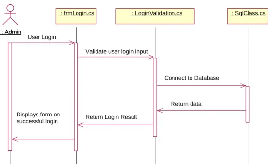
3.11.1 Login Use Case
Figure 3.9 Login sequence diagram
Figure 3.11 shows the sequence diagram for the user login case. The user enters his/her
login details and clicks the "Login” button in the frmLogin.cs form.
This click event triggers btnLoginClick() function which calls Validate Login() in
LoginValidation.cs class. This class validates the login details against the database.
SQLClass.cs class manages the database connection and returns the connection string
back to LoginValidation.cs class. If the validation is successful, a new session is started
else an error prompt is displayed.
: Admin : Admin
: frmLogin.cs
: frmLogin.cs : LoginValidation.cs : LoginValidation.cs : SqlClass.cs : SqlClass.cs
User Login
Validate user login input
Connect to Database
Return data Return Login Result
Displays form on successful login
3.11.2 Add new RMA use case
Figure 3.10 Add new RMA sequence diagram
Figures 3.12 shows sequence diagram for add a new RMA use case. The front-end view
for this use case is frmAddNewRMA.cs[design]. The btnSave_Click() function is
triggered on the button click which validates the user input. On successful validation,
InsertData() function is called, to insert data into the database table tbl_RMA.
3.11.3 Add new SLT use case
: Admin : Admin
: frmSLTTest.cs
: frmSLTTest.cs : SqlClass.cs : SqlClass.cs
Enter new SLT Test Results
Connect to database
Return data
Display success message
: Admin : Admin
: frmAddNewRMA.cs
: frmAddNewRMA.cs : SqlClass.cs : SqlClass.cs
Enter new RMA Details
Connect to database
Return data
Figure 3.13 shows sequence diagram for „add new SLT‟ use case. The front-end view
for this use case is frmSLTTest.cs[design]. The btnSave_Click() function is triggered on
the button click which validates the user input. On successful validation, InsertData()
function is called, to insert data into the database table tbl_slt_test.
3.11.4 Add new SMT use case
: Admin : Admin
: frmSMTTest.cs
: frmSMTTest.cs : SqlClass.cs : SqlClass.cs
Enter new SMT Test Results
Connect to database
Return data
Display success message
Figure 3.12 Add new SMT sequence diagram
Figures 3.14 shows sequence diagram for add new SLT use case. The front-end view for
this use case is frmSMTTest.cs[design]. The btnSave_Click() function is triggered on
the button click which validates the user input. On successful validation,
InsertUpdateData() function is called, to insert or update data into the database table
tbl_smt_test.
3.11.5 Add new Visual data
Enter new Visual Data : Admin
: Admin
: frmVisualTest.cs
: frmVisualTest.cs : SqlClass.cs : SqlClass.cs
Connect to database
Return data
Display success message
Figure 3.13 Add new Visual Data sequence diagram
Figure 3.15 shows sequence diagram for add new Visual data use case. The front-end
view for this use case is frmVisualTest.cs[design]. The btnSave_Click() function is
triggered on the button click which validates the user input. On successful validation,
InsertUpdateData() function is called, to insert or update data into the database table
tbl_visual_test.
3.11.6 Search module details
: Admin : Admin
: frmViewModule.cs
: frmViewModule.cs : SqlClass.cs : SqlClass.cs
Search module details
Connect to database
Return data Display module details by LOT ID
Figure 3.16 shows sequence diagram for add new Visual data use case. The front-end
view for this use case is frmViewModule.cs[design]. The btnSearch_Click() function is
triggered on the button click which validates the user input. On successful validation,
GETRMADetails() function is called, to fetch data from the database table tbl_RMA
based on search criteria.
3.11.7 Messaging service
Figure 3.15 Messaging Service sequence diagram
3.12 Overview of software components developed
View
Controller
Data Access
Database table
frmAddNewRMA
frmAddNewRMA.cs
SQLClass.cs
tbl_RMA
FrmOverview
FrmOverview.cs
SQLClass.cs
tbl_rma
frmSLTTest
frmSLTTest.cs
SQLClass.cs
tbl_slt_test
frmSMTTest
frmSMTTest.cs
SQLClass.cs
tbl_smt_test
: Admin : Admin : frmMdiMain.cs : frmMdiMain.cs : SqlClass.cs : SqlClass.cs Accept SMS request Connect to database Return data Return response
Table 3.1: Main software components created for Windows application
View
Controller
Data Access
Database table
Login.aspx
SQLClass.cs
tbl_RMA
Default.aspx
FrmOverview.cs
SQLClass.cs
tbl_rma
Viewmoduledetails.aspx
frmViewModule.cs
SQLClass.cs
tbl_slt_test
Table 3.2: Main software components created for Web application
Additional feature
Description
Reporting
Custom made excel exporting functionality
SMS Gateway
Messaging functionalities
Table 3.3: Other software components
CHAPTER 4: TESTING AND RESULTS
4.1 Testing Objectives
Software testing is an investigation conducted to validate and verify the purpose of a
computer program. It helps to assure the functionalities of the program and understand
the risks in implementing the software.
Main objectives of testing are:
1. To find bugs or errors when executing a computer program.
2. To meet the functional requirement of the stakeholder.
frmVisualTest
frmVisualTest.cs
SQLClass.cs
tbl_visual_test
4.2 Software Testing Methods
Software testing methods are generally classified into White box and Black box testing.
4.2.1 White - Box Testing
White box testing is a method for testing the internal working of a computer program. A
white box test case guarantees all independent paths within a program to be executed at
least once, tests whether all logical decisions are on their true or false sides and tests for
infinite loops.
Most commonly used white box testing technique is the Basis path testing which enables
the test case designer to derive a logical work flow of a procedural design and use this
guideline to design a set of execution paths. Test cases are derived from these set of
execution paths which guarantee that every paths are executed at least once.
4.2.2 Black - Box Testing
Black-box testing focuses on testing the functional requirements of the software. Internal
working of a software program or algorithm is not taken into consideration during black
box testing. Black-box testing aims at finding incorrect or missing functions, interface
errors, errors in data structures or external data base access, behavior or performance
errors, initialization and termination errors.
4.3 Software Testing Strategy
Software testing strategy is developed depending upon the requirements during
definition phase. The various testing methods outlined in our project planning phase are:
4.3.1 Unit Testing
A unit is a smallest individual function or program of a source code A unit can be a class
or interface. These unit are independent from other methods, functions, stubs and
Unit testing is a testing practice which ensures that these units are fit for use .Unit
testing is a type of white box testing which is conducted in parallel with other forms of
testing.
4.3.2 Integration Testing
After unit testing, it is necessary to ensure that these units work well when integrated
with the source code. The main issues faced during integration are data loss during
transition from interface to interface and effect of one function on another.
To address these issues, we use Integration testing technique. Integration testing is a
systematic technique for constructing the program structure while at the same time
conducting tests to uncover errors associated with interfacing. The objective is to take
unit tested components and build a program structure that has been dictated by design.
4.3.3 Validation Testing
At the end of integration testing when the interfacing errors have been revealed and
corrected, we begin validation testing. Validation testing can be defined as technique
which ensure that the software functions as expected during the initiation phase.
Requirements document outlined during the design phase forms the basis of validation
testing.
4.3.4 System Testing
System testing is a form of black box testing which does not require the knowledge
about the inner working of the code. System testing ensures that the software works
properly on any available hardware systems.
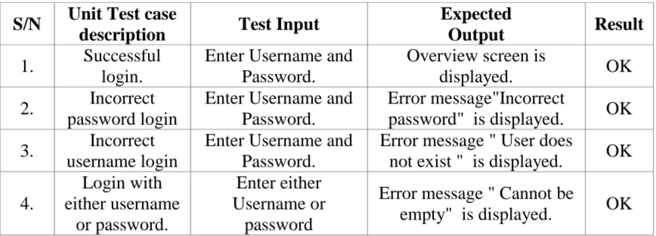
4.4 Test Cases for IDRS Desktop Application
Figure 4.1 Login Page
Figure 4.1 shows the login screen. The user enters his/her username and password in
their corresponding textboxes.
On unsuccessful login,
1. An error message "Incorrect password" is displayed if password is incorrect for the
username
2. An error message "User does not exist" is displayed if username is incorrect.
3. An error message "Cannot be empty" is displayed if either username or password is
empty.
Unit and Validation Test records
S/N
Unit Test case
description
Test Input
Expected
Output
Result
1.
Successful
login.
Enter Username and
Password.
Overview screen is
displayed.
OK
2.
Incorrect
password login
Enter Username and
Password.
Error message"Incorrect
password" is displayed.
OK
3.
Incorrect
username login
Enter Username and
Password.
Error message " User does
not exist " is displayed.
OK
4.
Login with
either username
or password.
Enter either
Username or
password
Error message " Cannot be
empty" is displayed.
OK
After entering the data, user clicks the 'Login' button. On successful login, the user is
directed to the 'Overview ' screen i.e. Figure 4.2.
Figure 4.2 Overview Page
4.4.2. Add a new user Test
To add a new user Go to File > New User which opens a pop up form to enter new user
details. After entering the new user login name and password, re-enter the same
password again for confirmation.
Click the Save button. On successful user creation a message "Successfully added new
user". (Figure 4.4)
Figure 4.3 Add User
If data is missing for any of the above fields, "All fields required" message is displayed.
Figure 4.4: Missing fields
S/N
Unit Test case
description
Test Input
Expected
Output
Result
1.
Add a new
user
1. Enter the new user
name and Password.
2. Re-enter the same
password.
Successfully added a
new user message
box is displayed.
OK
2.
Validate add
new user
Enter data with missing
fields.
All fields required
message is displayed.
OK
Table 4.2: Unit and Test Validation for „Add new user‟
4.4.3. Search module details by lot ID
Figure 4.5 Search module details
Press "View Module" button in the menu bar to go to the "View module" screen. In the
Search Module screen, module details can be searched by LOT ID.
To view the module and test results, enter the LOT ID and Click the "Search" button.
The module details and test results corresponding to the LOT ID will be displayed
below.
The test results for the module will be displayed on the right hand side of the screen(
Figure 4.5)
Unit and Validation Test records
S/N
Unit Test case
description
Test Input
Expected
Output
Result
1.
To view module
details and test
results
Enter the LOT ID and
Click the "Search"
button
Module details and
test results will be
displayed.
OK
2.
Display error
message for an
invalid LOT ID
Enter the LOT ID and
Click the "Search"
button
Display the error
message
OK
Table 4.3: Unit and Test Validation for Search function
4.4.4. Add RMA data
To add RMA details, go to "Add Data" > "New RMA item(s)" which loads a Data entry
form for RMA (Figure 4.6).
RMA number and Module LOT ID are mandatory data fields. If the user fails to fill up
these fields the system prompts them with an error message as shown in the Figure 4.7
and Figure 4.8.
Figure 4.7 RMA Error Message 1
Figure 4.8 RMA Error Message 2
Click the "Save" button after entering the data. A success message (Figure 4.9) will be
displayed on successful save operation.
Figure 4.9 Save RMA
Unit and Validation Test records
S/N
Unit Test case
description
Test Input
Expected
Output
Result
1.
To add new
RMA details.
Enter the RMA data details
and click the "Save"
button.
"Successfully
saved data" is
displayed.
OK
2.
Validate
"Module LOT
ID" field.
Click the "Save" button
after omitting the module
lot id data entry.
"Module LOT ID
cannot be empty"
is displayed.
OK
3.
Validate "RMA
Number" field.
Click the "Save" button
after omitting the RMA
Number data entry.
" RMA Number
cannot be empty"
is displayed.
OK
4.4.5. Add SMT details
To add SMT details, go to "Add Data" > "SMT results" which loads a Data entry form
for SMT.
ATE EMP is a mandatory data field. If the user fails to fill up this field the system
prompts them with an error message as shown in the Figure 4.10.
Figure 4.10 SMT Error
Click the "Save" button after entering the data. A success message (Figure 4.11) will be
displayed on successful save operation.
Figure 4.11 Add SMT
Unit and Validation Test records
S/N
Unit Test case
description
Test Input
Expected
Output
Result
1.
To add new
SMT details.
Enter the SMT data details
and click the "Save" button.
"Successfully
saved data" is
displayed.
OK
2.
Validate “ATE
EMP“ field.
Click the "Save" button after
omitting the ATE EMP data
entry.
"ATE EMP
cannot be empty"
is displayed.
OK
Table 4.5: Unit and Test Validation for „SMT‟
Figure 4.12: Add SLT
To add SLT details, go to "Test Results" >"New Test Result" >"SLT" which loads a
Data entry form for SLT.
SLT EMP and System model are mandatory data fields. If the user fails to fill up any of
these fields, the system prompts with an error message as shown in the Figure 4.13.
Figure 4.13: SLT Errors
Unit and Validation Test records
S/N
Unit Test
case
description
Test Input
Expected
Output
Result
1.
To add new
SLT details.
Enter the SLT data details and
click the "Save" button.
"Successfully saved
data" is displayed.
OK
2.
Validate
“SLT EMP“
field.
Click the "Save" button after
omitting the SLT EMP data
entry.
"SLT EMP cannot
be empty" is
displayed.
OK
3
Validate
“System
Model“ field.
Click the "Save" button after
omitting the System Model
data entry.
"System Model
cannot be empty" is
displayed.
OK
4
Validate “Lot
ID“ field.
Click the "Save" button after
omitting the Lot ID data entry.
"Lot ID cannot be
empty" is
displayed.
OK
4.4.7 Add visual data
To add visual data, go to "Add Data" > "Visual data " which loads a Data entry form for
visual data.
Select the LOT ID from the drop down and Select the test result i.e. "Pass" or "Fail".
Images can be uploaded by clicking the "Browse" buttons as shown in the figure. A
preview of the image uploaded is shown on successful upload.
Click the "Add new" button after entering the data. A success message (Figure 4.12) will
be displayed on successful save operation.
Figure 4.14 Visual data
Unit and Validation Test records
S/N
Unit Test case
description
Test Input
Expected
Output
Result
1.
To add new
visual data
details.
Enter the visual data details
and click the "Add new"
button.
"Successfully saved
visual test results" is
displayed.
OK
2.
Upload
images.
Click the Browse and
Select the image from form,
Image preview will
be displayed.
OK
Table 4.7: Unit and Test Validation for Visual data
4.5 Web application
Figure 4.13 shows the overview page of the web application. Details of all the pending
modules are displayed on this page as in Desktop application. This is the page displayed
upon successful login to the system.
Press "View Module Details" button in the menu bar to go to the "Module Details" page.
Module details of any module can be searched by LOT ID in particular.
To view the results, enter the LOT ID and Click the "Submit" button. The module details
corresponding to the LOT ID will be displayed below as in Figure 4.15.
Figure 4.17: Search page
Unit and Validation Test records
S/N
Unit Test case
description
Test Input
Expected
Output
Result
1.
To view module
details
Enter the LOT ID and
Click the "Submit" button
Module details will
be displayed.
OK
2.
Display error
message for an
invalid LOT ID
Enter the LOT ID and
Click the "Submit" button
Display the error
message
OK
Figure 4.18: Module Details page
4.6
Messaging service
To receive RMA module details on any mobile device, send an SMS as mentioned in the
use case.
S/N
Unit Test case
description
Test Input
Expected
Output
Result
1.
To view module
details
Send SMS with RMA
action
Module details will
be displayed
OK
2.
Validate SMS
format
Send SMS
Invalid message
format. Reply
HELP to get
available options
OK
3.
Validate LOT
ID or ACTION
Send SMS
No data to display
OK
4.
To view SLT
details
Send SMS with SLT action
SLT details will be
displayed
OK
5.
To view SMT
details
Send SMS with SMT
action
SMT details will be
displayed
OK
6.
To view visual
details
Send SMS with visual data
action
Visual data details
will be displayed
OK
Help
„Help‟ is the query to get the latest formats that need to be followed to retrieve the data
from the system. All the formats will be sent to the number as shown in Figure 4.16.
Login Validation
An error message of “invalid user name or password” will be returned in case of an
invalid entry of either username or password as shown in Figure.
RMA Details
Details of any pending module can be retrieved to any phone by sending an SMS to the
system in the format shown in Figure 4.17.
Test Results
Any test result of a particular module can be retrieved with its Lot ID by sending an
SMS to the system in a suitable format as shown in below figures. Detailed result will be
sent to the mobile within seconds after sending the SMS.
SLT Results
Visual Test
Comment Function
Comment can be added to any particular module on the client system by sending an
SMS in the format shown in Figure 4.21.
CHAPTER 5: PROJECT MANAGEMENT
5.1 Project Planning
The below table and Gantt chart consists of four main phases of the project. These
phases are:
1.
Project initiation
2.
Design and Development
3.
Testing & Troubleshooting
4.
Project completion.
Below are the brevity description for each main phase and its sub tasks.
5.2 Project Initiation
i.
Research on Software tools – Comprehensive search has been done on
internet to get an insight into the software tools.
ii.
Research on current products in market – Research on current systems to get
a better understanding of the design and architecture.
iii.
Project Proposal – Write a detailed proposal to describe what is this project
about, why this project and how to make this project a success.
iv.
Learning how to use software tool – To learn how to use software such as
Microsoft Visual Studio 2010 and SQL Server express 2008 R2.
5.3 Design and Development
i.
Define and Develop Software Requirement – Using UML notation such as
use case to define and develop the requirement.
ii.
Interface Requirement – Using Human Computer Interaction (HCI) skill as a
guideline for interface requirement.
iii.
Prioritize and Integrate Software Requirements – List the most significant
requirement first and then integrate them as a whole.
iv.
Design Architectural Design – Using the requirements as the input, concept
of UML static and dynamic models as the processor to produce the
architectural design of IDRS System.
v.
Design Database – Modelling the IDRS database using Entity-Relationship
model and normalize the database using Fourth Normal Form technique.
vi.
Design Detailed Design – Add in the details and finalize all the designs.
vii.
Preparation for Examination Period
5.4 Testing & Troubleshooting
i.
Create Test Data – To produce the data for testing purposes in the later part.
ii.
Create Source – Write the source code using C#, ASP .Net
iii.
Perform Integration – execute the integration plan accordingly to produce the
actual IDRS system.
iv.
Plan Testing – Plan testing activities such as component inspection, usability
tests, unit testing, integration testing and system testing.
v.
Develop Test Requirements – Develop and document the test requirement.
vi.
Execute the Tests – run the planned tests and document the result.
5.5 Project Completion
Basically, this main phase is to produce the final report, poster and preparation for the
poster presentation to obtain the grading for this project.
5.6 Effort Calculation
Tasks and Schedule for Capstone Project
S/N
Task Name
Duration
Start
End
Effort
(hrs)
Project Initiation Phase
74
1
Project Discussion with supervisor
1 Day
12-Feb-11
12-Feb-11
2
2
Research on the existing Projects.
3 Days
13-Feb-11
15-Feb-11
6
3
Literature research
18 Days
16-Feb-11
5-Mar-11
40
4
Preparation of Proposal
12 Days
21-Feb-11
4-Mar-11
20
5
Review and Submit Proposal
3 Days
5-Mar-11
7-Mar-11
6
Design and Development Phase
206
6
Learn more about SQL
18 Days
18-Feb-11
7-Mar-11
20
7
Start design the database schema
10 Days
26-Feb-11
7-Mar-11
15
8
Create database and Setup proper hosting
environments
20 Days
09-Mar-11
28-Mar-11
15
9
Design database
30 Days
20- Mar-11
18-Apr-11
60
10
Develop client application features
30 days
1-Apr-11
29-Apr-11
60
13
Preparation of the Interim report
20 Days
18-Apr-11
07-May-11
30
14
Review and Submit of interim report
2 Days
07-May-11
09-May-11
6
Testing & Troubleshooting Phase
392
15
Prepare and test the program using visual
studio.
7 Days
11-May-11
18-May-11
15
16
Test the modules
21 Days
19-May-11
08-Jun-11
40
17
debug and troubleshoot the system
40 Days
10-Jun-11
20-Jul-11
50
18
Research on more functions to implement on
the system and clear the drawbacks
54 Days
21-jul-11
12-Sep-11
120
19
Discuss with Tutor on the evaluation and
further
Improvement of this project
3 Days
13-Sep-11
15-Sep-11
9
Final Report Phase
20
Preparation of Final Report
50 Days
16-Sep-11
5-Nov-11
100
21
Discuss with tutor on Final Report
1 Day
06-Nov-11
06-Nov-11
3
22
Review and Submit Final Report
8 Days
07-Nov-11
14-Nov-11
20
23
Prepare Poster presentation
18 Days
16-Nov-11
03-Dec-11
35
Phase
Effort Hours
Project Initiation Phase
74 hrs
Design and Development Phase
206 hrs
Testing & Troubleshooting Phase
200 hrs
Final Report Phase
192 hrs
Total Hrs
672 hrs
Total Man-Days
103 days
Table 5.2: Total Effort hours
As having a full-time job and other UniSIM modules‟ commitment, it is literally
impossible to dedicate 6.5 hours per day to this project. Hence, the average hour that can
be spend on this project day is 2 hours, then 672 hours (336 days x 2 hours = 672 hours)
will be invested. As a result, it falls into the UniSIM requirement which is 400 - 600
hours. So the total effort required for this project is 103 days (672 hours / 6.5
man-day hours = 103 man-man-days).
Figure 5.1: Gantt chart – Project Initiation & Design and Development Phase
Figure 5.2: Gantt chart – Testing & Troubleshooting and Final Report Phase
Planned Effort
Actual Effort
5.7 Resources Required
The required resources for making this project successful are:
Computer to run the so

![Figure 3.16 shows sequence diagram for add new Visual data use case. The front-end view for this use case is frmViewModule.cs[design]](https://thumb-us.123doks.com/thumbv2/123dok_us/922458.2619318/38.893.197.745.317.676/figure-shows-sequence-diagram-visual-data-frmviewmodule-design.webp)