GOCE: SPACE TECHNOLOGY FOR THE REFERENCE EARTH GRAVITY FIELD DETERMINATION
A.Allasio1 - D.Muzi2
B.Vinai1, S.Cesare1, G. Catastini1, M.Bard3, J.P. Marque4
1) Thales Alenia Space, Italy 2) ESA, ESTEC, The Netherlands
3) Thales Alenia Space, France 4) Onera, France Abstract
Launched in March 2009, the Gravity Field and Steady State Ocean Circulation Explorer (GOCE) satellite is the first of the Earth Explorer Core Missions within ESA’s Living Planet Programme.
The aim of the GOCE mission is to provide global and regional models of the Earth’s gravity field and of the geoid, its reference equipotential surface, with high spatial resolution and accuracy. Such an advance in the knowledge of the Earth’s gravity field will help to develop a much deeper understanding of the physics of the Earth’s interior, the interaction of the continents, the ocean circulation and the climate change. The gravity field measurement is obtained using a axis Gradiometer composed by 6 three-axis ultra sensitive accelerometers and by a precise GPS receiver. In order to detect the tiny signals produced by the highest order (up to 200) harmonics of the geo-potential, the GOCE operational altitude has been set below 270 km. For this reason, GOCE has a peculiar aerodynamic configuration with a minimal cross section (~1.1 m2) in the flight direction.
Moreover, the spacecraft has been built to endow the gradiometer with an extremely stable dynamic environment, achieved through the utilization of low CTE materials, avoidance of any mechanism, minimization of micro-vibration sources and continuous compensation of the non-gravitational forces acting on the satellite by means of drag-free control system based on a throttable ion thruster.
The paper will, briefly recall the mission, its expectations, its challenges and the
performances of the satellite, with focus on the innovative elements technologies.
1. Introduction
The GOCE Mission is a first in many ways. It is the first of the Earth Explorer Core Missions of the ESA’s Living Planet Programme. Moreover it is the first ESA mission dedicated to the exploration of the Earth Gravity field and the first flying a three axis Gradiometer and a Drag Free and AttitudeControl (DFAC).
The mission objective of GOCE is to provide unique models of the Earth’s gravity field and of the geoid on a global scale with high spatial resolution and accuracy, for a large variety of applications.
Thales Alenia Space Italia is the industrial prime contractor supported by a core team consisting of EADS Astrium (platform), Thales Alenia Space France (Gradiometer instrument) and ONERA (Gradiometer accelerometers and satellite performances support).
The GOCE satellite has been successfully launched on March 17th 2009 from the Plesetsk
Cosmodrome (Northern Russia) with a Rockot launcher, and is about to complete the payload calibration phase (i.e. June 2009).
2. Scientific Objectives and applications
The aim of the GOCE Mission is to provide a global, high-resolution map of Earth’s gravity field geo-potential with homogeneous and unprecedented accuracy:
• 1 mgal (or10-5 m/s2)on the gravity anomaly,
• 1-2 cm on the height of the geoid (= equipotential surface for a hypothetical ocean at rest),
• at 100 km or less spatial resolution, equivalent to degree and order equal to or higher than 200 in a spherical harmonics expansion of the field.
The gravity field recovery will be achieved on a global scale, with the exception of a limited area in proximity of Earth’s poles.
The main scientific disciplines taking advantage of the GOCE data are:
Geophysics
Accurate gravity field maps enable to provide a new understanding of the physics of the Earth´s interior including geodynamics associated with the lithosphere, mantle composition, uplifting and subduction processes, and to deliver information of relevance to the study of Earthquakes, Volcanoes and other natural hazards.
Oceanography
The precise estimate of the marine geoid, in combination with satellite altimetry, allows the determination of the absolute ocean currents and associated transportation of heat and other properties fundamental for the improvement of the climatic models.
Glaciology
The combination of the geoid and gravity field maps with altimetric data will enable the improvement of the estimate of the thickness and mass of the polar ice sheets.
Geodesy
The high resolution overall geoid map will provide a better global height reference system for datum connection, which can serve as a reference surface for the study of topographic processes, including the evolution of ice-sheets and land-surface topography.
As shown in the following table, GOCE performance can suite a wide scientific application fields.
Application Accuracy Geoid [cm] Accuracy, Gravity [mGal] Spatial Resolution (1/2 λ)[km] Solid Earth Lithosphere and upper-mantle density structure 1-2 100 Continental lithosphere: •sedimentary basins •rifts •tectonic motions •Seismic hazards 1-2 1-2 1-2 1 50-100 20-100 100-500 100 Ocean lithosphere
and interaction with
asthenosphere 0.5-1 100-200 Oceanography Short-scale 1-2 0.2 100 200 Basin scale ~0.1 1000 Ice Sheets Rock basement 1-5 50-100 Ice vertical movements 2 100-1000 Geodesy Levelling by GPS 1 100-1000 Unification of worldwide height systems 1 100-20 000 Inertial Navigation System ~1-5 100-1000 Orbits ~1-3 100-1000
Table 1 – Measurement requirements for GOCE products applications
3. The Mission
The achievement of the mission objectives is obtained if GOCE flies as low as possible taking into account the constraint generated by the evolution of the predicted atmospheric density. Considering that the solar flux is evolving toward the maximum of the solar cycle (even if for the time being we are in an exceptionally low and prolonged minimum) the mission profile has been defined assuming, as major requirement, the capability to safely recover the scientific mission in case of contingency. Therefore air
density becomes the key parameter which drives the mission profile.
GOCE is currently flying on a circular sun-synchronous dusk-dawn orbit (Figure 1) with inclination 96.7°, at an altitude close to 270 km. Under the effect of the aerodynamic drag, GOCE is slowly decaying at about 200 m/day. The decay will be halted by firing an ion thruster at the operational altitude when the mean aerodynamic force on the satellite will be such to allow drag free operation all along the orbit (i.e. > 2mN average). In the mean time, the Gradiometer is being calibrated to be ready for starting the first Measurement Operation Phase (MOP1) of six months as soon as the long-eclipses season will be over, at the beginning of September 2009. During this phase the Drag Free and Attitude Control function will compensate the non gravitational forces experienced by the S/C in the flight direction and will align the spacecraft to the Local Orbital Reference Frame (LORF).
At the occurrence of the successive long-eclipses season (there is one per year and lasts about 4.5 months) the measurements will be nominally be suspended (depending on the status of solar activity and on board resources status, it may be possible to continue measurement operation also during this phase) and the orbit altitude will be re-adjusted according to the value of the aerodynamic force (depending on the solar activity evolution). A second Measurement Operation Phase (MOP2) will be performed before completing the nominal mission lifetime of 20 months. A mission extension to 30 months (including a further hibernation phase and a MOP3) will be performed if allowed by the on board consumables.
4. Satellite Design Description
4.1 Configuration and challenges
The main design drivers of the satellite configuration have been:
• The minimization of the air drags forces and torques.
• The minimization of the torque resulting from the coupling of the residual magnetic dipole moment of the satellite with the Earth’s magnetic field.
• The minimization of the measurement errors induced by the structure distortions.
• The provision of a highly stable thermal environment to the Gradiometer.
• The stability and knowledge of the alignments inside the Gradiometer and between the Gradiometer and the star trackers.
• The avoidance of intentional and minimization of unintentional micro-vibration sources.
• The engineering constraints imposed by the Launch Vehicle (volume, mass, interfaces)
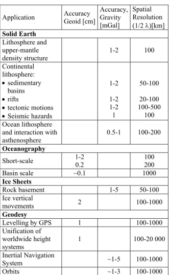
Figure 2 -GOCE Configuration Figure 1 – The GOCE sun-synchronous orbit
Nitrogen Tank Battery CDMU Gradiometer IPA / IPCUs Xenon Tank GCDE SSTI Ant 1 SSTI Ant 2 MGMs CESS 2-3-5 S-B Antenna LRR dummy PCDU Star Trackers LRR SBTs SSTIs CESS 4-6 CESS 1 S-B Antenna MTRs Solar Wing
As a consequence the satellite body has an octagonal prism shape, 5.3 m long and with a transversal cross section of 1.1 m2 (Figure 1)
equipped with two long, fixed solar array wings fitting the launcher fairing dynamic envelope (triple-junction GaAs solar cell technology has been used to generate the maximum power) Two fins placed on the rear part of the satellite (one is visible in Figure 3) enhance the passive aerodynamic stability, while the S-band and GPS antenna and sensor appendages mounted on a wing rim are replicated on the other wing for maintaining a symmetrical cross section.
A highly stable structure has been implemented in the Platform and into the Gradiometer; thermo-elastic distortion analysis and test have been conducted to validate design and to verify the stringent alignment requirements. The thermal environment stability is maximized by the sun-synchronous dusk-dawn orbit, in which the sun illuminates always the same side of the satellite, and by selection of the long-eclipses free periods for performing the measurements. The Gradiometer is accommodated such as to
get its COM near to the COM of the satellite and the position of GPS antenna has been measured relatively to the satellite COM with an accuracy of ~1 mm.
No deployable and other sort of mechanisms are used, while extensive micro-vibration campaign including, unit internal design guidelines, development testing and verification analyses has been carried out for minimizing micro-disturbances and thermal clanks.
The residual magnetic dipole moment of the satellite has been minimized by design, measured, and compensated.
5. The Payload
Two instruments constitute the primary GOCE payload: the Electrostatic Gravity Gradiometer (EGG) and the Satellite to Satellite Tracking Instrument (SSTI), based on precise GPS receiver.
The two instruments are complementary. The EGG is particularly sensitive to the short-wave length part of the geopotential whereas the SSTI works best at providing the long-and medium-wavelength part.
5.1 The Gradiometer
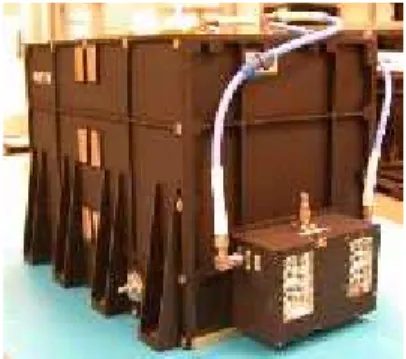
The EGG consists of a set of six 3-axis capacitive accelerometers developed by ONERA, mounted in a diamond configuration on an ultra-stable Carbon/Carbon structure developed on purpose by Thales Alenia Space France (Figure 4). A pair of accelerometers, separated by 50 cm, forms a ‘gradiometer arm’.
Three identical gradiometer arms are mounted orthogonal to one another, and, in orbit, the three arms are aligned to the in-track, cross-track and radial directions.
The differential accelerations measured by the three gradiometer arms contain the signals of the three “diagonal” components of the Earth’s gravity gradient (in-track, cross-track, radial) and of the three off-diagonal ones. The gradiometer also provides the measurements (in-track common-mode acceleration and angular accelerations) driving the satellite drag-free and attitude control system (DFACS). DFACS data are provided at 10Hz while the more accurate scientific data are generated at 1 Hz.
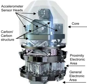
The EGG is configured as a self-standing payload, with its own structure, thermal control and electronics, designed to provide to the accelerometer the level of dimensional stability and signal processing accuracy required to fulfill the outstanding goals of the mission. The EGG is functionally organized in three areas as shown in Figure 5:
• the Gradiometer Core, where the accelerometers are located, thermally controlled to a very high degree of stability. • the Proximity Electronics Area, containing
the 3 Front End Electronic Units (FEEUs, one for each accelerometer pair), is an area of high thermal stability close to the accelerometes for avoiding signal losses. • the General Electronics Area, containing the
units in charge of the EGG management, including the precise control of the proof masses position and of the temperature.
The dimensional stability of the Gradiometer core is a fundamental parameter to fulfill the measurement goals. This stability is ensured thanks to a combination of a very high stable material with unprecedented thermal control performances: stability <5×(0.1Hz/f)2 µK/√Hz in
MBW, i.e. one order of magnitude better than that needed by advanced optical instruments. Thanks its low sensitivity to moisture and its high stiffness-to-mass ratio, complementary to its very good thermo-elastic characteristics (CTE of -1×10⁻⁷ °C-1), the Carbon-Carbon composite
material has been selected and applied for building very strong sandwich panels for manufacturing the structure of the 3 Gradiometer arms (Figure 6). These sandwich panels are made of Carbon-Carbon sheets associated to Carbon-Carbon honeycombs; the CTE of the sandwich is the result of the proper combination of the sheets and of the honeycomb characteristics.
Figure 4 – Gradiometer Core
Figure 5 - Electrostatic Gravity Gradiometer
Core Proximity Electronic Area General Electronic Area Accelerometer Sensor Heads Carbon/ Carbon structure
5.2 The Accelerometer
Three axes electrostatic accelerometers developed at ONERA are based on the electrostatic levitation of an inertial mass. Measurements of the voltages necessary to create the electrostatic forces and torques which will maintain the mass motionless with respect to the sensor cage, provide the outputs of the accelerometer.
The Pt-Rh, 320g, proof mass (PM) is free to move within the cage (Figure 7) as no blocking system is implemented. The cage is made of ULE plates on which 8 electrodes pairs are engraved and gold coated. Four pairs are dedicated to sensitive axes (Y-Z translations and
Φ rotation) and four pairs are used for the remaining X translation and Θ-Ψ rotations. The 6 translation and angular degrees of freedom (dof) of the PM motion are obtained by an appropriate combination of the 8 electrode channels. This configuration allows, thanks to the implementation for the first time of an analog-digital control loop for each of the 8 electrodes channel, flexibility and redundancy in the 6 dof retrieval.
The electrode-PM gap defines the capacitance of the PM position detector working at 100 KHz and of the PM position actuator which control voltage is updated at 1024 Hz.
X Y,Z 32 µm 299 µm
Nominal PM-electrode gap values
The only mechanical links between the proof-mass and the core is a 5 µm gold wire allowing to polarise the proof-mass, avoiding any variation of the patch effect in orbit.
Mechanical stops are implemented within the core to prevent any direct contact with core electrodes. The PM-stop gap, when centred, is 15 µm along X and 30 µm along Y and Z axes. So, impacts of the proof-mass motion under vibration loads during launch and qualification/acceptance test had to be minimised. They consist in stress induced in ULE plates under proof-mass shocks on the stops and in possible material transfer between them leading to the risk of a strong reduction of proof mass free motion belowacceptable range. Specific development activities were devoted to assess these two points.
To maintain the core cleanliness, to shield the proof mass against the magnetic field and ensure the performance of the sensor, the core is enclosed in a hermetic housing and the vacuum is ensured by a ionic pump during the ground functional test and passively by the getter after delivery (Figure 8).
Figure 7: Accelerometer Sensor Head (ASH-02) ULE core containing the Pt-Rh proof mass. The lower metallic structure is the “sole plate” providing the reference frame interface with the carbon-carbon gradiometer arm.
Figure 6 – Carbon-Carbon structure of one axis of the Gradiometer
Figure 8: ASH-05 before delivery to Thales Alenia Space Gradiometer Team. On the top of the ASH, there is the ionic pump used during functional test on ground and the getter housing.
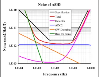
The performance of an accelerometer is defined by its intrinsic noise in the frequency band from 5 mHz to 100 mHz. This band corresponds to the gravity field signals which need to be detected with the highest possible accuracy. Most of the engineering design activity consisted in reducing as much as possible the noise of the various contributors within that measurement bandwidth (MBW).
The expected noise of the six accelerometers and their detection chain (estimated from ground measurements on the electronics and performance models) is shown on Figures 9 (where the main noise contributors are also shown) and Figure 10. The main noise contributors are:
• The position detector noise (pink line). • The wire damping (orange line). Minimized
by the use of a 5µm diameter gold wire, the effect of the wire damping in the control loop produces a noise level limit which remains far below the requirement.
• The readout ADC quantization noise (blue line)
• The thermal sensitivity of the bias (green line). The temperature variation, despite of the thermal control of the gradiometer, leads to the variation of the accelerometer bias at low frequency. The main contributor is the thermal sensitivity of the radiometer effect,
due to the difference of temperature between the faces of the proof-mass.
Noise of ASH3
1.E-13 1.E-12 1.E-11 1.E-10
1.E-04 1.E-03 1.E-02 1.E-01 1.E+00
Frequency (Hz) N oi se ( m /s 2/ H z1/ 2) Specification Total Detector ADC2 GW Damping Bias Th. Sens
Figure 9: Estimated noise performance of the GOCE Accelerometric Chain of ASH-03
Noise of ASH
1.E-12 1.E-11
1.E-03 1.E-02 1.E-01 1.E+00
Frequency (Hz) N oi se ( m /s 2/ H z1/ 2) Specification ASH1 ASH2 ASH3 ASH4 ASH5 ASH6
Figure 10: Estimated noise performance of the 6 GOCE Accelerometric Chains
With an acceleration range of ±6.5×10⁻⁶ ms-2 in
Science Mode, we obtained a signal dynamic larger than 3×10⁶. The design effort is
appreciable when compared to the performance level of the accelerometers of the CHAMP and GRACE missions: 3.0×10⁻⁹ ms-2/Hz1/2 and 1.0×10⁻¹⁰ ms-2/Hz1/2 respectively.
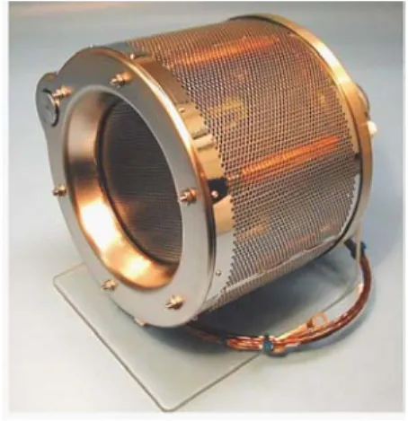
5.3 Satellite-to Satellite Tracking Instrument The SSTI (Figure 11), developed by Thales Alenia Space Italia, is composed of a receiver pair and the associated antennas. The integrated Global Navigation Satellite System (GNSS) receiver can track up to 12 GPS satellite signals, in two frequencies, providing measurements of code and carrier phase signals.
It is also able to provide real-time navigation data (position, velocity and time) using GPS C/A signals with an accuracy of 40 m and 0.16 m/s (3D, 3σ). By processing on ground the carrier phases, the GOCE orbital path can be determined with a precision of few centimeters. From the analysis of the orbital perturbations the Earth gravity field (lower harmonics) can be finally obtained.
Figure 11: The SSTI receiver
The GOCE payload comprises as well a secondary instrument, a Laser Retro-Reflector (LRR), for corroborating the measurements of the satellite position in the centimeter range. The LRR consists of an array of 7 corner Cubes symmetrically mounted on a hemispherical frame with one corner cube in the centre of the top face, surrounded by an angled ring of 6 corner cubes. This arrangement endows the LRR with field of view angles of 360º in azimuth and 60º elevation around the perpendicular to the top face of the LRR. The LRR is located on the Earth-facing side of the satellite so that the optical axis of the upper corner cube is aligned to the nadir direction.
6. The Platform
The GOCE Platform concurs in the EGG
performance in a fundamental way by providing the necessary dynamic environment for it to work properly.
6.1.1 Structure
The primary structure is an octagonal central body composed of 8 sandwich side panels connected each other by lashings along the longitudinal direction and stiffened by 7 sandwich horizontal floors used for accommodating the equipments. All the primary structure is made of CFRP composite to achieve stiffness and weight requirements and to minimize the thermal elastic distortion of the spacecraft, in order to reduce the impacts of both the misalignment between gradiometer and star sensors and the self-gravity effects to the gravimetric measurements.
The floors carrying electronic units are in Aluminium skin sandwich for better distribution of the heat, while the star sensors and the Xenon tank floors are in CFRP to get better stiffness and/or dimensional stability.
Four body mounted solar arrays, fixed on the primary structure, are covering half of the octagon, while two additional radial panels, called solar wings, fixed along two opposite corners of the cylinder complete the solar array provision utilising the full dynamical envelope of the launch vehicle (Rockot) fairing.
The structure mechanical design has been thoroughly investigated by analyses and tests. In particular detailed transmissibility analyses have been executed to assess the micro-vibration aspects of the system, to evaluate the sources to receivers signal transfer function and for evaluating the corresponding motion of the accelerometers proof masses.
Thermal-distortion analyses have been conducted to study the alignment changes due to in flight temperature distributions.
Predictions and structural tests have demonstrated the quality of mechanical design; innovation includes a Modal Survey Test executed in the frame of the sinusoidal test.
Thermal Control of the satellite is mainly achieved by means of passive techniques of insulation and radiation, using radiators coated with ATOX inert Optical Solar Reflectors (OSR), MLI blankets, paints, heaters and thermistors.
The thermal control concept consists in dividing the instrument into two thermal domains to minimize the temperature variations in the Gradiometer core:
the inner passive thermal domain with the Gradiometer itself (i.e. the structure and the accelerometers) that insulates the gradiometer core from the external environment
the outer active thermal domain with the electronics, that is a regulated area which ensures a very stable environment.
The design choice of placing thermal insulation and radiators, kept predominantly on the S/C sides grant minor variation in the external thermal heat flux, optimizing thermal and self-gravity field stability of the satellite.
Special care, followed by development testing and analyses, has been applied in selecting the proper MLI, for minimizing scientific measurement disturbance due to mechanical stress release in surface bumps occurring typically during thermal excursion.
6.1.3 Propulsion
The propulsion is the key element in ensuring the satellite drag-free control performance and for such purpose an Ion Propulsion Assembly (IPA) has been installed for the orbit control and the linear acceleration control in the flight direction. Two ion propulsion branches, in cold redundancy are located on the lower module of the platform.
The GOCE ion propulsion (Figure 12) is capable of delivering continuous thrust with:
• thrust level between 0.6 and 20 mN
• thrust command step between 170 and 250 µN. • slew rate between 1.7 to 2.5 mN/s @10Hz • thrust vector migration during the mission
not exceeding +/- 0.9 deg
• thrust noise with a spectral density not exceeding 50×(0.28Hz/f) µN/√Hz in MBW.
Each propulsion branch includes:
• an Ion Thruster with thrust vectors directed towards the S/C COM. This orientation allows both thrusters to compensate the atmospheric drag along the orbit velocity without creating spurious torques.
• a Xenon Feed System enclosed in a box for minimizing the micro disturbance produced by the flow control valve.
• an Ion Propulsion Control Unit (IPCU) providing the thruster and feed system control as well as supplying the necessary high voltage.
A tank with 40 Kg of Xenon, sufficient for the entire mission, is then supplying both branches.
6.1.4 Gradiometer Calibration Device A Gradiometer Calibration Device (GCD) provides sequences of linear and angular pseudo-random accelerations to the satellite for highlighting the effect of the different scale factors and alignments between the accelerometers, and thus measuring them with high accuracy.
The GCD is a cold gas (Nitrogen) system, using 8 thrusters with a fixed thrust of 600-800 µN, commanded by a Gradiometer Calibration Device Electronic. A tank with 14 Kg of Nitrogen is installed on board for providing up to 20 calibrations (each calibration consisting of 24 hours of continuous shaking) along the mission.
6.1.5 Avionics
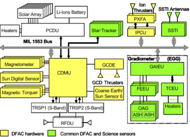
The GOCE avionics provide for all functions of power provision, commandability, observability, autonomy, failure identification, correction and recovery, and time synchronisation, in support of the scientific measurements. A block diagram of the avionics is shown in Figure 13.
The Electrical Power Subsystem consists of solar array using the state of art triple-junction Ga-As, delivering 1.6 kW EOL, 75 Ah battery, providing energy in eclipse and covering power peaks, and Power Control and Distribution Unit. The electrical power is distributed to the payload and platform users via an unregulated 22-34 Vdc power bus.
Data processing is performed in a central processor, which also provides to the DFAC tasks by means of dedicated software. Local data processing is also performed in the two main payloads. Data traffic uses a centralised MIL-STD-1553 data bus; a limited number of analogue and discrete signals is provided to users or wherever required by initial activation, safety and reliability. In the proposal reference design, an integrated Command and Data Management Unit (CDMU) includes dedicated boards for remote terminal unit functions and for 4 Gbit mass memory.
A standard S-band system ensures the link with Earth for telemetry command and ranging (backup to the GPS-based navigation). The RF system provides omnidirectional coverage for
any satellite attitude both in uplink and downlink.
The absence of switching and electromagnetic devices involving moveable parts, is a characteristic feature of GOCE because of the extreme sensitivity of the EGG.
6.2 Drag Free and Attitude Control
The Drag Free and Attitude Control (DFAC) is a key subsystem for achievement of the mission performances. It is in charge of smoothly controlling the satellite to the target reference attitude and to reduce the linear acceleration experienced by the satellite in the flight direction due to the air density variations down to a level of 2.5×10⁻⁸ m/s2/√Hz in the MBW.
For the linear acceleration control, the DFAC is fed directly by the measurements of the Gradiometer accelerometers. Each accelerometer is in fact endowed with a “DFAC channel” delivering to the platform measurements at 10 Hz (10 times the frequency of the science channel), which is the frequency of the digital drag-free control loop. For the attitude control, the angular accelerations obtained from a combination of the six accelerometer measurements are hybridized with the angular measurements of three Star Trackers (utilized in hot redundancy) for a precise estimation of the attitude dynamics. The LORF axes directions to which the satellite axes has to be kept aligned, are estimated from the orbital position and velocity provided in real-time by the SSTI.
The set of attitude sensors of GOCE is completed by:
• two Digital Sun Sensors (DSS) in hot redundancy
• six heads of the Coarse Earth and Sun Sensors (CESS) internally redundant
• three 3-axis magnetometer (MGM) in hot redundancy
The linear acceleration control is achieved through the ion thruster, while the attitude control rely only on three (internally redunded) magnetic torquers (reaction wheels would be too noisy and no qualified micro-thrusters were available at the beginning the GOCE implementation phase).
DFAC hardware Common DFAC and Science sensors Magnetometer
Sun Digital Sensor Magnetic Torquer GCDE GCD Thrusters CDMU TRSP1 (S-Band) TRSP2 (S-Band) RFDU MIL 1553 Bus Gradiometer (EGG) GAIEU TCEU Heaters FEEU ASH OAG ASH Coarse Earth/ Sun Sensor 6 SSTI Antennae SSTI Ion Thrusters IPCU PXFA Li-Ions Battery PCDU
Heaters Start Tracker Solar Array
DFAC hardware Common DFAC and Science sensors Magnetometer
Sun Digital Sensor Magnetic Torquer GCDE GCD Thrusters CDMU TRSP1 (S-Band) TRSP2 (S-Band) RFDU TRSP1 (S-Band) TRSP2 (S-Band) RFDU MIL 1553 Bus Gradiometer (EGG) GAIEU TCEU Heaters FEEU ASH OAG ASH Gradiometer (EGG) GAIEU TCEU Heaters FEEU ASH OAG ASH Coarse Earth/ Sun Sensor 6 SSTI Antennae SSTI SSTI Antennae SSTI SSTI Ion Thrusters IPCU PXFA Ion Thrusters IPCU PXFA Li-Ions Battery PCDU
Heaters Start Tracker Solar Array Li-Ions Battery
PCDU
Heaters Start Tracker Solar Array
Solar Array
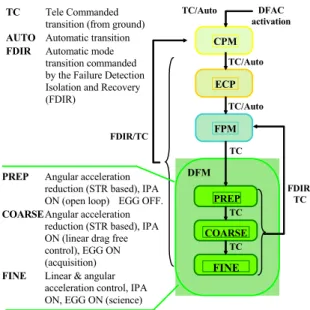
The DFAC has been organized in four main control modes and three sub-modes (Figure 8). The Coarse Pointing Mode (CPM) is in charge of satellite de-tumbling after the separation from the launcher, Sun/Earth acquisition and pointing. The Extended Coarse Pointing Mode (ECPM) points the satellite is the LORF for limiting the altitude decay (minimum cross section exposed to the air flux) and ensuring that no Star Tracker isblindedby the Earth.Orbit raising manoeuvres in contingency conditions are performed in ECPM.
The Fine Pointing Mode (FPM) is a transition mode, where pointing performance improvements are achieved by the introduction of Star Tracker attitude measurements.
Drag-Free Mode (DFM) comprises three sub-modes. In DFM Preparation the ion thruster generates a constant thrust which compensates the average value of air drag force in order to allow a safe switch on of the EGG. In DFM Coarse the EGG, commanded in acquisition mode is included in the control loop and the ion thruster is used in proportional way to compensate the instantaneous drag force. Also the attitude control in this mode requires a change in the resolution of the commanded torque to get a smooth angular acceleration. For
this purpose, the magnetic torquers are actuated by fine current drivers. The DFM Fine is the scientific mode in which the EGG is used at its maximum resolution (EGG in science mode). DFM Fine is also employed to operate the in-flight calibration of the gradiometer via the GCD.
The DFAC performance in attenuating the linear acceleration along the flight direction has been already verified in the frame of the commissioning activities. The results are by far better than the requirement and expectations (Figure 15). It is the first time ever that such a drag-free condition is established on a low Earth orbiting satellite.
7. Performance verification
The measurement performances of the Gradiometer cannot be fully verified on ground, first of all because the gravity saturates the ultra-sensitive accelerometers, and because the background noise in the laboratory environment is orders of magnitude larger than the expected sensor noise. Therefore since the beginning of the GOCE project effort have been spent to set up a high fidelity simulator, faster than the real time, needed to support design, trade-off analyses, development and verification, prediction and assessment of performance. The scheme of this simulator, called End to End Simulator, is shown in Figure 16.
PREP DFM CPM FPM ECP COARSE FINE DFAC activation TC/Auto TC/Auto TC TC TC FDIR/ TC FDIR/TC TC Tele Commanded transition (from ground)
AUTO Automatic transition
FDIR Automatic mode
transition commanded by the Failure Detection Isolation and Recovery (FDIR)
TC/Auto
PREP Angular acceleration
reduction (STR based), IPA ON (open loop) EGG OFF.
COARSE Angular acceleration reduction (STR based), IPA ON (linear drag free control), EGG ON (acquisition)
FINE Linear & angular acceleration control, IPA ON, EGG ON (science)
Figure 14 - DFAC modes and transitions
Figure 15 – Residual linear acceleration in flight direction
The simulator solves for the GOCE dynamics along an orbit resulting from the application of Earth’s gravity field (EGM96 model complete up to degree and order 360), non-conservative environmental disturbances (atmospheric drag, coupling with Earth’s magnetic field, etc.) and control forces/torques. The drag free control forces, as well as the attitude control torques, are generated by the DFAC algorithms which are fully integrated in the simulator. Sensors (DSS, CESS, MGM, Star Tracker, SSTI receiver and EGG) feeding the control algorithms and actuators (ion thruster, magnetic torquers, GCD) generating the commanded forces and torques, are represented by high-fidelity SW models either obtained by the subcontractors or developed by Thales Alenia Space Italia.
All the mission phases and DFAC modes can be reproduced by the End to End Simulator.
The capability of the simulator to provide long telemetry data stream, covering the duration of a whole MOP (6 months) in the same satellite telemetry format, has been very useful for the validation of the GOCE ground segment data processing, including the Gradiometer Calibration Facility.
The End to End Simulator is currently used for verifying the possible presence of anomaly in the on-orbit behaviour of the satellite and of its payloads, by comparing the flight data with the numerical predictions.
The decisive verification of the in-flight performance of the Gradiometer and of the whole satellite is obtained from the computation of the “trace of the gravity gradient tensor”, i.e. the sum of the three “diagonal” components of the Earth’s gravity gradient (in-track, cross-track, radial). By physical property, this trace shall be nominally zero. Therefore any deviation from the zero value can be attributed to a measurement error (due to intrinsic accelerometer noise, instability of the gradiometer structure, disturbances generated by the platform, etc.). The mission objective is considered achieved if the spectral density of the gravity gradient trace, after the Gradiometer calibration, is below:
100 mE/√Hz at 5 mHz frequency 18 mE/√Hz at 10 mHz frequency
11 mE/√Hz between 20 and 100 mHz frequency (1 mE = 10-12 m/s2/m is a measurement unit of
the acceleration gradient).
The current performance expectation, computed with the End to End Simulator on the basis of the most reliable models available of the satellite, of its payload, and of the orbital environment, is shown in Figure 17. The performance predictions take into account the instrument errors as described in paragraph 5.2 as well as the effects of the satellite in its environment and processing errors. The proof that this performance has been actually achieved will be available soon, just after the completion of the Gradiometer calibration which is currently in progress. Dynamics ENV OSW Gravity field gradient MGM CESS DSS STR EGG SSTI DFAC algorithms Sensors Pre-processor Actuators Post-processor STR telemetry EGG telemetry SSTI telemetry Science data processing & calibration Level 1b products: - Gravity gradients - Precise Orbit MTR IPA GCA GPS Constellat.
ENV: Environmental Perturbations OSW: Outside World (gravity & magnetic fields…)
Figure 16 – GOCE End To End Simulator scheme
8. Conclusions
Despite being a very challenging mission, due to the usage of several new and sophisticated technologies and techniques, the GOCE satellite has behaved so far according to the expectations and even better. The stringent drag-free control requirement is met and Gradiometer calibration is positively progressing, confirming the expectation that also the very demanding scientific performances will be met.
9. Acknowledgments
The authors of this paper express their deep gratitude to all the people in Industry, scientific institutes and ESA that with their work and commitment made possible the realization of one of the most complex satellites ever built.
1 10 100 1000 1 10 100 1000 frequency [mHz] [m E/sqrt(Hz)] 5 delta_Uxx delta_Uyy delta_Uzz GGT trace Trace requirement 1 10 100 1000 1 10 100 1000 frequency [mHz] [m E/sqrt(Hz)] 5 delta_Uxx delta_Uyy delta_Uzz GGT trace Trace requirement delta_Uxx delta_Uyy delta_Uzz GGT trace Trace requirement