PARTIAL CARBON CAPTURE AND STORAGE RETROFIT TECHNICAL APPENDIX I. Carbon Capture Retrofit is Demonstrated
Integrated carbon capture systems are technically feasible and available in the power sector and in other industries.1 Retrofitting existing sources with carbon capture is demonstrated and sequestration is feasible for most existing sources and can lead to substantial reductions in CO2 emissions.
As early as 2001, the National Energy Technology Laboratory (“NETL”) found that there are no major technical barriers to carbon capture retrofit.2 Existing plants generally apply post-combustion capture technology because it can be retrofitted to the flue gas processing system at low cost, allowing the combustion process to remain substantially unchanged.3 Post-combustion is an end-of-the-pipe pollution control and can be installed without significant modification to the plant.4 Current post-combustion capture uses electricity from the plant to provide heat to regenerate the solvent and power CO2 compression, which results in an “efficiency penalty.”5 However, a wide range of options exist for effective integration of CO2 capture equipment with the steam cycles of existing coal and gas power plants, allowing electricity output penalties per ton of CO2 captured to be achieved that are close to those for new build plants using the same capture technology.6 One option is to add a gas turbine combined heat and power cycle instead of integrating the retrofit with steam extraction from the main power cycle.7 It is expected that
1See generally Comment submitted by Clean Air Task Force (CATF), Technical Appendix, Doc. ID No. EPA-HQ-OAR-2013-0495-11005 (May 12, 2014) (describing describe the current status of integrated CCS projects on power plants, and in other industrial applications in the U.S. and around the world, and then collect and describe the current status of projects employing each of the component technical elements of CCS – capture, compression,
transportation, and injection –whether for EOR or sequestration in depleted oil and gas fields or deep saline geologic formations) (App. Ex. 1). See also generally Global CCS Institute, “Submission to The European Commission’s Evaluation Process of the Directive on the Geological Storage of Carbon Dioxide,” (Aug. 27, 2014) (providing an update on the status of CCS globally) (App. Ex. 2). These comments will focus specifically on CCS retrofit and should be read in conjunction with CATF’s forthcoming comments on the ESPS.
2 C. Bozzuto et al., DOE NETL, Engineering feasibility and economics of CO2 capture on an existing coal-fired
power plant (2001) (App. Ex. 3).
3 Chao Fu and Truls Gunderson, Carbon Capture and Storage in the Power Industry: Challenges and Opportunities, 16 ENERGY PROCEDIA 1806, 1808 (2012) (App. Ex. 4); See also Geoffrey P. Hammond and Jack Spargo, The prospects for coal-fired power plants with carbon capture and storage: A UK perspective, 86 ENERGY CONVERSION
&MGMT. 476, 477 (2014) (App. Ex. 5).
4 Mathieu Lucquiaud and Jon Gibbins, Effective retrofitting of post-combustion capture to coal-fired power plants
and insensitivity of CO2 abatement costs to base plant efficiency, 5 INT’L J. OF GREENHOUSE GAS CONTROL 427
(2011) (App. Ex. 6). 5Id.
6 Jon Gibbons et al., Techno-economic assessment of CO2 capture retrofit to existing power plants, 4 E
NERGY
PROCEDIA 1835 (2011) (describing “six rules for effective thermodynamic integration of post-combustion capture
and CO2 compression.”) (App. Ex. 7). See also Mathieu Lucquiaud and Jon Gibbons, Steam cycle options for the retrofit of coal and gas power plants with post-combustion capture, 4 ENERGY PROCEDIA 1812 (2011) (App. Ex. 8). 7See generally Mathieu Lucquiaud et al., Carbon capture retrofit options with the on-site addition of gas turbine
combined heat and power cycle, 37 ENERGY PROCEDIA 2369 (2013) (App. Ex. 9). IEAGHG, Retrofitting CO2 Capture to Existing Power Plants, at 21-22 (May 2011) (App. Ex. 7). Other options include fully integrated retrofit; boiler heat-matched retrofit; boiler heat and power matched retrofit; advanced coal boiler retrofit; gas turbine heat matched retrofit; and solar thermal systems.
future solvent improvements will continue to reduce CCS efficiency penalties for retrofits, with those currently under development reducing penalties by 2.5 percent.8 In fact, the net energy penalty for amine solvent capture decreased by 26 percent between 2005 and 2012.9
Existing plants can also use oxy-combustion technology by retrofitting the combustion system.10 Oxy-combustion retrofit requires addition of an air separation unit, CO2 scrubbing and compression to the conventional plant.11 While post-combustion technology may be easier to retrofit, oxy-combustion results in a lower “reduction in power efficiency and…increment of investment for CO2 capture.”12 A recent risk analysis for an oxyfuel combustion retrofit on a 560 MWe power plant found that the retrofit and operation “would only involve low magnitude risks and no critical risk at all.”13 Existing plants cannot utilize pre-combustion capture.14
The Electric Power Research Institute (“EPRI”) recently performed detailed economic and engineering studies to determine the feasibility of retrofitting five existing, North American, pulverized coal (“PC”) and/or circulating fluidized-bed (“CFB”) plants with post-combustion capture and found that all sites were technically capable of 90 percent retrofit.15 Another recent study commissioned by the IEAGHG concluded, “a general rejection of retrofitting on grounds such as age or lower efficiency of existing plants is not justified.”16
The issues associated with CCS retrofit are generally site-specific and depend on the characteristics of the plant and the capture technology installed. The most important of them are access to suitable CO2 storage and space on-site17 for additional equipment associated with capture.”18 But even though most existing plants were not originally designed to operate with CCS “they can achieve performance with capture close to a plant built with capture from the outset independently of the initial plant steam conditions and efficiency with appropriate steam turbine retrofits.”19
CCS retrofits costs are reasonable especially in light of the extensive emission reductions achievable and the fact that without CCS, existing power plants will be forced to retire
prematurely in order to avoid the most dangerous climate change, resulting in significant
8 Desmond Dillon et al., A Summary of EPRI’s Engineering and Economic Studies of Post Combustion Capture
Retrofit Applied at Various North American Host Sites, 37 ENERGY PROCEDIA 2349, 2357 (2013) (App. Ex. 10). 9 Kristin Gerdes, DOE NETL, Powerpoint, “NETL Studies on the Economic Feasibility of CO2 Capture Retrofits for the U.S. Power Plant Fleet,” (Jan. 9, 2014) (App. Ex. 11).
10See Chao Fu and Truls Gunderson, (App. Ex. 4) supra note 3 at 808. See also Geoffrey P. Hammond and Jack Spargo, (App. Ex. 5) supra note 3 at 477.
11 Geoffrey P. Hammond and Jack Spargo, (App. Ex. 5) supra note 3 at 478. 12 Chao Fu and Truls Gunderson, (App. Ex. 4) supra note 3 at 1809.
13 Kati Kupila et al., Risk Analysis of FORTUM’s 560MWe net Power Plant Retrofit to Oxyfuel Combustion, 4 ENERGY PROCEDIA 1820, 1821 (2011) (App. Ex. 12).
14 Umberto Desideri and Marco Antonelli, A simplified method for the evaluation of the performance of coal fired
power plant with carbon capture, 64 APPLIED THERMAL ENG’G 263-64 (2014) (App. Ex. 13).
15 Desmond Dillon et al., (App. Ex. 10) supra note 8 at 2357. 16 Jon Gibbins et al., (App. Ex. 7) supra note 6 at 1836.
17 Jia Li et al., An assessment of the potential for retrofitting existing coal-fired power plants in China, 4 E
NERGY
PROCEDIA 1805, 1811 (2011) (App. Ex. 14). For most plants, however “there is the potential to have at least partial retrofit, which means retrofitting only some of the generating units rather than the whole power plant.”
18 Jon Gibbins et al., (App. Ex. 7) supra note 6 at 1838.
stranded assets.20 Retrofitting plants is a lower-cost option to reduce CO2 emissions than replacing the plant with an entirely new plant.21 A CCS retrofit can result in a levelized cost of electricity almost $50 less than a new build with CCS.22
Kristin Gerdes, DOE NETL, Powerpoint, “NETL Studies on the Economic Feasibility of CO2 Capture Retrofits for the U.S. Power Plant Fleet,” (Jan. 9, 2014) (App. Ex. 11).
The lower capital cost of retrofit on an existing plant over a new build can offset any additional costs associated with reduced efficiency and additional capture cost.23 Existing plants can take advantage of existing infrastructure, grid connections, water supplies, coal and gas delivery facilities and environmental permits.24 It was originally thought that the existing plant efficiency would have a dramatic effect on CCS costs,25 however recent studies have
found,“[p]rovided that effective capture system integration can be achieved…abatement costs …is independent of the initial plant efficiency.”26
Partial CCS retrofit meets the definition of BSER because it is achievable and adequately demonstrated “to serve the interests of pollution control without becoming exorbitantly costly in an economic or environmental way.”27
20 Nils Johnson et al., Stranded on a low-carbon planet: Implications of climate policy for the phase-out of
coal-based power plants, XX TECH.FORECASTING &SOC.CHANGE XXX (2014) (Article in press) (App. Ex. 15). 21 IEA, Technology Roadmap: Carbon Capture and Storage, at 29 (2013); See also generally Desmond Dillon et al., (App. Ex. 10) supra note 8 at 2349.
22 Desmond Dillon et al., (App. Ex. 10) supra note 8 at2356 (assuming that the retrofitted plant is paid off and will continue to operate for 30 more years).
23 Jon Gibbins et al., (App. Ex. 7) supra note 6 at1836. 24 IEAGHG (App Ex. 7) supra note 7 at ii.
25Id. at x.
26 Mathieu Lucquiaud and Jon Gibbins, (App. Ex. 6) supra note 4 at 427. 27Essex Chem. Corp. v. Ruckelshaus, 486 F.2d 427, 433 (D.C. Cir. 1973).
Reference Capture Plants:
Cost of Electricity
DRAFT Results 8 57 90 46 80 81 146 45 124 0 20 40 60 80 100 120 140 160 N on-Cap tu re 90 % C ap tu re Exi sti ng 90 % C ap tu re N on-Cap tu re 90 % C ap tu re Exi sti ng 90 % C ap tu re
Greenfield Retrofit Greenfield Retrofit
NGCC with NG @ $6.13/MMBtu PC C OE, 2011$/ MWh T&S Fuel Var O&M Fix O&M Capital
II. Most Existing Power Plants Have Sufficient Space to Add Carbon Capture
Equipment and a Significant Portion of Existing Power Plants Have Access to CO2
Sequestration Opportunities
Some commentators have identified the generalized problem of a dearth of space for capture equipment at existing plants as a potential limiting factor for CCS. However, as will be described below, research shows that for most modified sources, particularly those within 80 miles of CO2-EOR sequestration opportunities, and for all sources whose owners and operators are considering the significant investment decision characterizing reconstruction, partial CCS retrofit must form the basis for the MRSPS.
A 2010 NETL study evaluated the feasibility of adding retrofitted capture at existing power plant sites, using aerial and satellite images of the power plant site.28 No sites were considered totally infeasible for retrofit.29 And, for most plants, “there is the potential to have at least partial retrofit, which means retrofitting only some of the generating units rather than the whole power plant.”30 Different capture technology options, especially oxyfuel, may require less space and increase partial CCS retrofit potential.31But it is true that existing power plants are locked into their location and therefore a potential limit to installing CCS is access to CO2
sequestration opportunities, whether in EOR or saline geologic formations. Once CO2 is captured
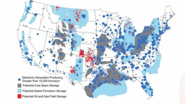
and compressed it must be transported, generally by pipeline, to sufficient storage. As the map below depicts, the majority of U.S. power plants are co-located or within a reasonable distance of potential storage options such as coal seam storage, saline formation storage or oil and gas field storage.
DOE/NETL, Carbon Dioxide and Storage RD&D Roadmap, at 45 (Dec. 2010) (App. Ex. 28).
28 IEAGHG, (App Ex. 7) supra note 7 at 84, 86. 29Id.
30 Jia Li et al., (App. Ex. 14) supra note 17 at 1811. 31 IEAGHG, (App Ex. 7) supra note 7 at 84, 86.
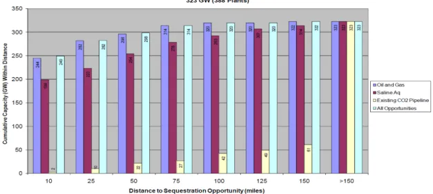
In 2010, NETL also performed a study that looked at 388 large, efficient, coal plants and found that 84 percent of them were within 25 miles of storage, 97 percent were within 100 miles of storage – 322 of the 323 GW examined were within 150 miles of storage.32
NETL found that “both transport and storage requirements for retrofits at a significant number of sites have a good chance of being met.”33
And CO2 pipeline infrastructure in the U.S. has expanded since 2011, and
continues to expand with market demand for even further buildout.34
In total, this system carried approximately 48 to 58 MMtpa of naturally mined and anthropogenic CO2 throughput in 2010,
35
and continues to grow to meet demand. 36
32 IEAGHG, (App Ex. 7) supra note 7 at 84-85. 33Id. at 84.
34 Kevin Bliss, et al.,A Policy, Legal, and Regulatory Evaluation of the Feasibility of a National Pipeline
Infrastructure for the Transport and Storage of Carbon Dioxide, (Sept. 10, 2010) available at:
http://www.secarbon.org/files/pipeline-study.pdf (App. Ex. 16); See also Advanced Resources International, U.S. Oil production potential from accelerated deployment of carbon capture and storage, at 2 (2010) available at:
http://www.adv-res.com/pdf/v4ARI%20CCS-CO2-EOR%20whitepaper%20FINAL%204-2-10.pdf (App. Ex. 17);. EPA estimates in 2013 that there are 3,600 miles of pipeline and also notes that 95% of the top 500 largest CO2 point sources are within 50 miles of a possible geologic sequestration site. 79 Fed. Reg. at 1472 (citingJJ Dooley et
al. Carbon Dioxide Capture and Geologic Storage: A Key Component of a Global Energy Technology Strategy to
Address Climate Change, Joint Global Change Research Institute (2006)); accord Jordan K Eccles, Lincoln Pratson,
A ‘carbonshed’ assessment of small- vs. large-scale CCS deployment, 113 APPLIED ENERGY352, 357 (2014)
available at: http://www.sciencedirect.com/science/article/pii/S0306261913005680(App. Ex. 18) (noting that “the
large, low cost carbonsheds for Mt. Simon and Frio [geologic sequestration formations] also coincidentally contain the majority of existing coal-fired power plants….”).
35 Phil DiPietro, et al., A Note on Sources of CO
2 Supply for Enhanced-Oil-Recovery Operations, (Apr. 2012)
available at: http://www.netl.doe.gov/File Library/Research/Energy
Analysis/Publications/SourcesofCO2SupplyforEOROperationsTechNote_0412.pdf (App. Ex. 19). 36See e.g. Denbury Resources Denbury Resources, “CO2 Sources and Pipelines – Gulf Coast Region,”
http://www.denbury.com/operations/gulf-coast-region/co2-sources-and-pipelines/default.aspx (App. Ex. 20). Construction of Denbury’s 325-mile Green Pipeline was completed in mid-December 2010; Denbury, “CO2 Sources and Pipelines – Rocky Mountain Region,” http://www.denbury.com/operations/rocky-mountain-region/co2-sources-and-pipelines/default.aspx (App. Ex. 21). Denbury also completed construction of 232 miles of the
Greencore CO2 pipeline in the Rocky Mountain region in late 2012; “Carbon dioxide injection starts in Oklahoma's
Figure 6.4 Distance to prospective storage locations for operating US coal plants
(100 miles = 160 km)
Figure 6.5 Estimated storage capacity (based on NETL NatCarb data – www.natcarb.org) for 282 GW (738 units) at operating US coal plants
IEAGHG, Retrofitting CO2 Capture to Existing Power Plants, at 84-85 (May 2011).
While there is extensive saline and coal seam storage available, due to the potential for modified sources to offset the costs of partial CCS with sale of captured CO2 to an EOR operator
for use, modified sources should be subcategorized on the basis of proximity to EOR
opportunities. The figure below shows that as of 2014, there are 136 CO2-EOR projects with
approximately 13,000 CO2 injection wells injecting over 73 million tons of CO2 annually. 37
And demand for anthropogenic CO2 is climbing to the support doubling of production and CO2
utilization by 2020.38
Kuuskraa and Wallace, CO2-EOR Set for Growth as New CO2 Supplies Emerge, OIL &GAS J. (Apr. 7, 2014) (App.
Ex. 23).
Burbank oil field,” OIL &GAS J. (July 8, 2013) available at: http://www.ogj.com/articles/print/volume-111/issue-7a/general-interest/carbon-dioxide-injection-starts-in-oklahoma-s.html (App. Ex. 22). In 2013, Chaparral Energy began operation of a 68-mile CO2 pipeline connecting the Coffeyville fertilizer plant to Burbank, Oklahoma to enable the use of the anthropogenic CO2 for EOR.
37 J. Meyer, API Background Report: Summary of Carbon Dioxide Enhanced Oil Recovery (CO2-EOR) Injection
Well Technology, available at: http://api.org/environment-health-and-safety/environmental-performance/~/media/D68DE1954B8E4905A961572B3D7A967A.ashx (App. Ex. 24). 38 Kuuskraa and Wallace, CO
2-EOR Set for Growth as New CO2 Supplies Emerge, OIL &GAS J. (Apr. 7, 2014)
CO2-EOR is available, and continuing to expand. To the extent that a modified subpart Da source is within 80 miles of an EOR opportunity, as it is in the case of the Petra Nova Carbon Capture Project, partial CCS is the BSER.
III. Power Generation Retrofit Projects
CCS retrofit is available for reconstructed and modified sources with access to storage, as demonstrated by a number of commercial-scale demonstration retrofits,39 and as well a recent full-scale integrated retrofit at existing coal-fired power plant units. Further, many of CCS retrofits to existing power plants are currently under development.
a. Boundary Dam Integrated Carbon Capture and Sequestration Demonstration Project
On October 2, 2014, Boundary Dam commenced operation and became the first full-scale coal-fired power plant CCS retrofit.40 The SaskPower project added post-combustion, absorption chemical solvent-based capture to a recently refurbished, 110 MW EGU (Unit 3 at Boundary Dam Power Station).41 Unit 3 was originally built in 1969 and was scheduled for retirement in 2013.42 SaskPower received approval from the Saskatchewan Government to build the project in April 2011.43 The project will capture 90 percent of the CO2 from the Unit or approximately 1 million Mtpa (MMtpa).44 CO2 from the project will be will be transported via a 60-mile pipeline, and both contained as a result of EORactivity (supplementing the existing CO2 supply to the Weyburn–Midale oil fields, captured and delivered from the Great Plains Synfuels plant, a coal gasification facility in North Dakota), and some will also be sequestered in a nearby deep saline formation as part of the Saskatchewan Aquistore project.45 Costs of the project were offset by
39See e.g. Plant Barry, MIT, “Plant Barry Fact Sheet: Carbon Dioxide Capture and Storage Project,”
https://sequestration.mit.edu/tools/projects/plant_barry.html; Mountaineer, MIT, “AEP Mountaineer Fact Sheet: Carbon Dioxide Capture and Storage Project,
https://sequestration.mit.edu/tools/projects/aep_alstom_mountaineer.html.
40 Maria Gallucci, World’s First Full-Scale Carbon Capture and Storage Project to Launch at Canada’s Boundary
Dam Plant, INT’L BUS.TIMES, Oct. 1, 2014, available at: http://www.ibtimes.com/worlds-first-full-scale-carbon-capture-storage-project-launch-canadas-boundary-dam-plant-1697926.
41 SaskPower, “Boundary Dam Integrated Carbon Capture and Storage Demonstration Project,”
http://www.saskpower.com/sustainable_growth/assets/clean_coal_information_sheet.pdf.
42 Global CCS Institute, “Boundary Dam Integrated Carbon Capture and Sequestration Demonstration Project,”
http://www.globalccsinstitute.com/project/boundary-dam-integrated-carbon-capture-and-sequestration-demonstration-project.
43 On September 12, 2012, Canada’s Minister for the Environment published final CO2 performance standards applicable to both new coal-fired EGUs and to coal-fired units that have reached the end of their useful lives.
Reduction of Carbon Dioxide Emissions from Coal-fired Generation of Electricity Regulations, SOR/2012-167 §§ 3(1), 2 (definitions of “old unit” and “useful life”), 146 C. Gaz. II, 19 (Sept. 12, 2012) available at:
http://www.gazette.gc.ca/rp- pr/p2/2012/2012-09-12/html/sor-dors167-eng.html.
44 Global CCS Institute, The Global Status of CCS 2013, Appendix A, at 12 (Feb. 2014), available at:
http://www.globalccsinstitute.com/publications/global-status-ccs-february-2014 [hereinafter Global Status of CCS 2014] (App. Ex. 25).
45 Global CCS Institute, “Boundary Dam Integrated Carbon Capture and Sequestration Demonstration Project,”
http://www.globalccsinstitute.com/project/boundary-dam-integrated-carbon-capture-and-sequestration-demonstration-project.
CO2 sales and utilizing existing infrastructure.46 Saskpower expects that learnings from the Boundary Dam project will result in a 20 percent electrical cost reduction and a thirty percent capital cost reduction.47
b. FutureGen 2.0 Project
FutureGen 2.0 is a 168 MWe project, which will involve repowering the 200 MWe Unit 4 at Ameren's power plant in Meredosia, Illinois, with oxy-combustion technology.48 1.1 MMtpa of CO2 will be captured and transported by pipeline to Morgan County, Illinois for sequestration in a deep saline formation up to a total of 24 metric tons (Mt) over twenty years.49 The U.S. Department of Energy (“DOE”) has stated that the plant's new boiler, air separation unit, CO2 purification and compression unit will deliver 90 percent CO2 capture and eliminate most SOx, NOx, mercury and particulate emissions.50 The project will be one of the world's largest applications of oxy-combustion technology.51 In January 2014 DOE issued its Record of Decision to provide financial assistance to the project.52 In February 2014, FutureGen received permission from Illinois regulators for a 30-mile underground pipeline that would carry the CO2 to an injection and saline sequestration site in northeast Morgan County, Illinois.53 On April 14, 2014, FutureGen signed an agreement with seventeen local unions to support the construction of the project.54 On August 29, 2014, EPA issued the first Class VI underground injection well permits to FutureGen for geologic sequestration of CO2 captured at the plant.55 Operation is expected to commence in 2017.56
c. Petra Nova Carbon Capture Project (also known as NRG Energy Parish CCS Project)
46 Mike Monea, President, Carbon Capture and Storage Initiatives, SaskPower, Powerpoint, “Sharing the Learning,” (2013) http://www.saskpowerccs.com/symposium/presentations/1 Mike Monea - Intro - May 20, 2013 - F I N A L .pdf (App. Ex. 26).
47Id.
48Global Status of CCS 2014 at 12; Global CCS Institute, “FutureGen 2.0”
http://www.globalccsinstitute.com/project/futuregen-20-project; MIT, “FutureGen Fact Sheet”
https://sequestration.mit.edu/tools/projects/futuregen.html. 49Id.
50 U.S. DOE, “Secretary Chu Announces FutureGen 2.0,” (Aug. 5, 2010) available at:
http://energy.gov/fe/articles/secretary-chu-announces-futuregen-20. 51 Global CCS Institute, “Hydrogen Energy California Project (HECA)”
http://www.globalccsinstitute.com/project/hydrogen-energy-california-project-heca. 52 79 Fed. Reg. 3,577 (Jan. 22, 2014).
53 Tim Landis, “Regulators Approve FutureGen 2.0 Pipeline,” T
HE STATE JOURNAL REGISTER, Feb. 24, 2014,
available at: http://www.sj-r.com/article/20140224/News/140229610.
54 FutureGen Alliance, Blog, “Labor Agreement Supports FutureGen’s Highly Skilled Workforce,” Apr. 14, 2014,
http://futuregenalliance.org/announcement/2014/04/labor-agreement-supports-futuregen’s-highly-skilled-workforce/. -
55 Michael Bologna, EPA Grants First Underground Injection Permits to FutureGen for Illinois Project, BNA BLOOMBERG NEWS, Sept. 4, 2014, http://www.bna.com/epa-grants-first-n17179894408/.
56Global Status of CCS 2014 at 12; Global CCS Institute, “FutureGen 2.0”
http://www.globalccsinstitute.com/project/futuregen-20-project; MIT, “FutureGen Fact Sheet”
NRG Energy plans to retrofit CO2 capture equipment on Unit 8, a 250 MWe slipstream,
at its W.A. Parish coal-fired power plant southwest of Houston, Texas.57 It will utilize Fluor’s
Econamine FG-Plus, post-combustion technology to capture approximately 1.5 MMtpa of CO2 or
90 percent of the CO2 from the flue-gas slipstream.58 The CO2 will be transported by an 82-mile
long pipeline to the Hilcorp West Ranch Oil Field in Jackson County Texas where it will be used
for EOR.59 The project already has a contract with DOE to sequester 400,000 Mtpa of CO2.60
The project is expected to be operational in 2016.61 The W.A. Parish project includes a number
of innovative technical advances. Specifically, the project’s proposed use of amine technology
specifically designed to capture CO2 from low-pressure coal plant flue gas streams that have
been scrubbed of virtually all ash, sulfur and nitrogen.62 The primary amine solvent ingredient
used in the process is readily available worldwide and inexpensive.63 The solvents have
relatively low energy consumption properties and, in addition, the industry is developing more
advanced solvents foreven better performance.64 Existing and future solvents can also be
deployed in this project for testing with coal-fired flue gas.65 Innovations in process equipment
performance planned for this project, such as absorber intercooling and lean solution vapor compression have the potential to reduce the energy requirements of these systems by as much as
20 percent.66 Additionally, efficiency improvements in the supporting balance of plant processes
such as process steam generation and CO2 compression will also reduce energy requirements.67
These advances are anticipated to lower carbon capture costs and increase system flexibility and
efficiency.68 A new 80 MW natural gas-fired turbine is currently under construction on the site to
provide the auxiliary electricity and steam necessary for the capture equipment.69 On May 23,
2014, DOE announced its decision “to provide NRG with $167 million in cost-shared funding for its proposed project through a cooperative agreement under DOE’s [Clean Coal Powering
Initiative] program.”70 On July 3, 2014, NRG, through its wholly owned subsidiary, Petral Nova
57 Global CCS Institute, The Global Status of CCS 2013, at 29, 38, 166 (2013) available at:
http://www.globalccsinstitute.com/publications/global-status-ccs [herineafter Global Status of CCS 2013] (App. Ex. 27); Global Status of CCS 2014 at 6; Global CCS Institute, “NRG Energy Parish CCS Project,”
http://www.globalccsinstitute.com/project/nrg-energy-parish-ccs-project; MIT, “W.A. Parish Fact Sheet,”
https://sequestration.mit.edu/tools/projects/wa_parish.html. 58 79 Fed. Reg. 30,901, 30,903 (May 23, 2014).
59Global Status of CCS of 2013 at 29, 38, 166; Global Status of CCS 2014 at 6; Global CCS Institute, “NRG Energy Parish CCS Project,” http://www.globalccsinstitute.com/project/nrg-energy-parish-ccs-project; MIT, “W.A. Parish Fact Sheet,” https://sequestration.mit.edu/tools/projects/wa_parish.html.
60Id. 61Id.
62 Petra Nova, “WA Parish CO2 Capture Project Fact Sheet,”
http://www.nrgenergy.com/pdf/factsheets/factsheet_waparish.pdf. 63Id.
64Id. 65Id. 66Id.
67 Petra Nova, “WA Parish CO2 Capture Project Fact Sheet,”
http://www.nrgenergy.com/pdf/factsheets/factsheet_waparish.pdf. 68Id.
69 78 Fed. Reg. 30,901, 30,903 (May 23, 2014). 70 78 Fed. Reg. 30,901, 30,902 (May 23, 2014).
Holdings LLC, formed a 50/50 joint venture with JX Nippon, to build and operate the project.71
The project is under construction and expected to be complete by the end of 2016.72
d. Peterhead CCS Project
Shell U.K Limited plan to retrofit a 385 MW slipstream at its existing Peterhead gas-fired power station with a CO2 post-combustion capture system, which will capture around 1 MMtpa of CO2.73 The CO2 would be sequestered approximately 160 miles offshore in the depleted Goldeneye gas reservoir.74 The project entered into a front-end engineering design (“FEED”) contract with the UK Government in February 2014.75 A final investment decision is expected in 2015 with the project to become operational in 2018.76
e. Rotterdam Opslag en Afvang Demonstratieproject (“ROAD”)
The ROAD Project is a proposed retrofit of a 250 MW post-combustion capture unit on a newly constructed 1,070 MW coal- and biomass-fired power plant.77 The project would capture approximately 1.1 MMtpa of CO2 and transport it via a 16-mile long pipeline for long-term sequestration in offshore, depleted oil and gas reserves at a depth of nearly 1,000 feet under the
seabed.78 Construction of the power plant has commenced and the demonstration phase is
expected to begin in 2017.79
71 NRG, New Release, NRG Energy, Inc. Reports Second Quarter Results; Completed First NRG Yield Drop Down and Announces Formation of NRG Home and NRG Renew, (2014)
http://phx.corporate-ir.net/phoenix.zhtml?c=121544&p=irol-newsArticle&ID=1956450. 72Id.
73Id. 74Id. 75Id.
76 NRG, New Release supra note 71.
77 Global CCS Institute, “Rotterdam Opslag en Afvang Demonstratieproject (ROAD),”
http://www.globalccsinstitute.com/project/rotterdam-opslag-en-afvang-demonstratieproject-road; MIT, “ROAD (Maasvlakte) Fact Sheet,” https://sequestration.mit.edu/tools/projects/maasvlkte.html.
78Id. 79Id.