model rockety pdf
46
0
0
Full text
(2) Table of Contents Technical Report TR-1, “Rocket Stability” .............................................1 Technical Report TR-2, “Multi-Staging”.................................................3 Technical Report TR-3, “Altitude Tracking” ...........................................7 Technical Report TR-4, “Rear Engine Boost Gliders” ..........................10 Technical Report TR-5, “Building a Wind Tunnel” ..............................13 Technical Report TR-6, “Cluster Techniques” ......................................21 Technical Report TR-7, “Front Engine Boost Gliders”.........................25 Technical Note TN-1, “Model Rocket Engines” ...................................28 Technical Note TN-3, “Is That Parachute Too Big?” ............................34 Technical Note TN-4, “The Fine Art of Payload Launching” ...............35 Technical Note TN-6, “Recovery Techniques”......................................39. Dedication To Vern and Gleda Estes who made model rocketry both possible and popular through their dedicated efforts. ©Copyright 1988, 1999 Centuri Corporation. All rights reserved.. EST. 2845 Rev. 10/99. ®. ESTES INDUSTRIES P.O. Box 227 Penrose, CO 81240 USA Most of the technical reports and technical notes in this publication are reprinted as they first appeared. However, certain parts have been updated to present accurate current technical data..
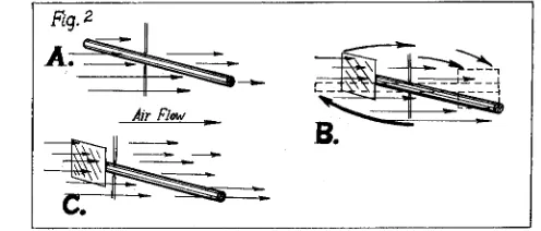
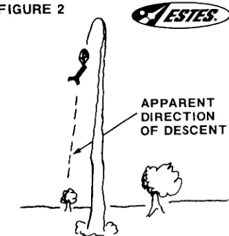
(3) Technical Report TR-1 Rocket Stability. ®. By Vernon Estes. These reports are published as a service to its customers by Estes Industries, Inc., Box 227, Penrose, Colorado.. One of the first principles any rocket designer must learn is that unless a rocket has a complex electro/mechanical guidance system, it will fly only if its center of gravity (also know as center of mass) is far enough ahead of the center of pressure to allow air currents to act against the rocket causing a stabilizing effect.. its rotating on the axis created between the two points). Suppose the dowel is held in a uniform air current (wind) of 10 to 15 miles per hour. If the pivot has been placed in the center of the dowel and if the dowel is uniform in size (area) the forces exerted by the air pressure will be equal on both sides of the pivot and the air current will produce no rotating effect. In this condition the center of gravity and the center of pressure will be at the same point.. From your science class or other scientific studies you have probably learned that if a rotating force is applied to a free body in space it will cause it to rotate around its center of gravity. As an example of this, you could take a wooden dowel or uniform stick about two feet long and toss it into the air so that it will rotate end over end (see Fig. 1, example A). You will notice that regardless of how you throw the stick, vertically or horizontally, hard or easy, it will always rotate about its center. If a weight is attached to one end of the stick and it is again thrown into the air it will rotate about a new location (Fig. 1, example B). This time the point about which it rotates will be closer to the weighted end. If you take the weighted stick and balance it across a sharp edge you will find that the point at which it balances (its center of gravity) is the same point about which it rotated when tossed into the air (Fig. 1, example C).. If a vane of 3” x 3” cardboard is glued to one end of the dowel and it is again put into the air stream with the pivot in the same position, the moving air current will exert the greatest force against the end of the dowel which has the vane attached to it as in example B of Fig. 2. This will cause the dowel to rotate until the end away from the vane points into the wind. If we now move the pivot closer to the vane end of the dowel we will be able to locate a point along the dowel where equal air pressure will be applied to both ends. The air current will no longer cause any part of the dowel to point into the wind. This point is called the lateral center of pressure. Remember, forces applied to the surface directly by air currents and the larger the surface, the greater the forces will be.. This simple explanation should aid you in understanding how a free body in space rotates around its center of gravity. A model rocket in flight is a free body in “space”. If, for any reason, a force is applied to the flying rocket to cause it to rotate, it will always do so about its center of gravity.. The ideal way to find the lateral center of pressure of a model rocket is to suspend the rocket between pivots as was done with the 2 foot dowel in Fig. 2, then hold the rocket in a uniform lateral air current. This can be accomplished to some degree of accuracy by holding the suspended rocket in a breeze of 10 to 15 m.p.h. The same affect can be accomplished very accurately by the use of a low velocity wind tunnel. However, since most model rocket builders and designers do not have wind tunnels and low friction pivots as described above, other methods must be provided for determining the center of pressure.. Rotating forces applied to rockets in flight can result from lateral winds, air drag on nose cones, weights off-center, air drag on launch lugs, crooked fins, engine mounted off-center or at an angle, unbalanced drag on fins, unequal streamlining, etc. Obviously, some of these factors are going to be present in all rockets. Therefore, since rotating forces will be present, your rocket must be designed to overcome them. If your rocket is not so designed it will loop around and go “everywhere”, but end up going nowhere. Nearly all model rockets are stabilized by air currents. By stabilized, we mean that all rotating forces are counteracted or overcome. This means that for each force trying to make the rocket rotate we must set up an equal and opposite force to counteract it.. Keep in mind the fact that the air pressure applied to a surface is proportional to the area of the surface. It then becomes possible to approximate the rotating effect of the action of the air pressure by making a uniform area cutout of your rocket and locating the balancing point of this cutout. To make this cutout, simply lay your rocket over a piece of cardboard and mark around the edges. Next, cut around the lines and balance the cutout on a knife-edge as shown in example B of Fig. 3.. How is this accomplished? Ask any rocket expert and he will simply say to design the rocket so the center of gravity is ahead of the center of pressure. From studying our first experiment it is easy to see how we could find the center of gravity by simply balancing the rocket on a knife edge as shown in example A of Fig. 3. But what and where is the center of pressure? The following experiment should aid you in understanding more about the center of pressure of a rocket. Suppose we take the same 2 foot long piece of dowel used in our first experiment and place it on a low friction pivot as shown in example A of Fig. 2. (The low friction pivot consists of two needlepoints held rigidly in place on opposite sides of the object by a heavy wire or board framework. The needlepoints are placeed against the object just tightly enough to hold it, without interfering with. 1. ®.
(4) This method will determine the lateral center of pressure (the center of pressure with the air currents hitting the rocket broadside). If the rocket is designed so the lateral center of pressure is 1/2 the body diameter (1/2 caliber) behind the center of gravity it will have ample stability under all reasonable conditions. If, however, the rocket’s fins are very crooked, set at opposing angles, or if the rocket uses a disc or cone for stabilizing, the lateral center of pressure should be set at least one diameter behind the center of gravity.. Apply a small piece of tape to hold the string in place. If the rockets center of gravity (balance point) falls in the fin area, it may be balanced by hooking the string diagonally around the fins and body tube as shown in Fig. 5. A common straight pin may be necessary at the forward edge of one of the fins to hold the string in place. This string mounting system provides a very effective low friction pivot about which the rocket can rotate freely. For the first system, slide a soda straw along the string to a position just above the rocket. Then suspend the rocket in a low velocity air stream (wind tunnel or gentle breeze) with the nose of the rocket pointing into the wind. Then turn the rocket approximately 10” out of the wind to see if it recovers. If so, the rocket is stable enough for flight.. In flight, of course, the rocket will not be traveling sidewards, but with its nose pointed into the wind. With the model’s nose pointed into wind, the location of the effective center of pressure will be affected by the shape of the fins, the thickness of the fins, the shape of the nose cone, location of the launching lug, etc. With most designs this shift is to the rear, adding to the stability of the rocket.. The second method involves swinging the suspended rocket overhead in a circular path around the individual, as shown in Fig. 7. If the rocket is stable, it will point forward into the wind created by its own motion. If the center of pressure is extremely close to the center of gravity, the rocket will not point itself into the wind unless it is pointing directly forward at the time the circular motion is started. This is accomplished by holding the rocket in one hand, with the arm extended, and then pivoting the entire body as the rocket is started in the circular path. Sometimes several attempts are required in order to achieve a perfect start. If it is necessary to hold the rocket to start it, additional checks should be made to determine if the rocket is flight-worthy.. Suppose a model rocket starts to rotate in flight. It will rotate around its center of gravity. When it turns the air rushing past it will then hit the rocket at an angle. If the center of pressure is behind the center of gravity on the model, the air pressure will exert the greatest force against the fins. This will counteract the rotating forces and the model will continue to fly straight. If, on the other hand, the center of pressure is ahead of the center of gravity the air currents will exert a greater force against the nose end of the rocket. This will cause it to rotate even farther, and once it has begun rotating it will go head over heels in the air.. Small wind gusts or engine misalignment can cause a rocket that checks out stable when started by hand as described above to be unstable in flight. To be sure that the rocket’s stability is sufficient to overcome these problems, the rocket is swung overhead in a state of slight imbalance. Experiments indicate that a single engined rocket will have adequate stability for a safe flight if it remains stable when the above test is made with the rocket rebalanced so the nose drops below the tail with the rocket body at an angle of 10 degrees from the horizontal (see Fig. 8). With cluster powered rockets a greater degree of stability is needed since the engines are mounted off center. The cluster-powered rocket should be stable when imbalanced to hang at 15 degrees from the horizontal. Heavier rockets which accelerate at a lower rate require a similar margin of stability.. It is easy to see from this why it is best to build the rocket with its fins as far as possible to the rear. The farther behind the center of gravity the center of pressure is placed, the stronger and more precise will be the restoring forces on the model, and it will fly straighter with less wobbling and power-robbing side-to-side motion. Under no circumstances should fins be placed forward of the center of gravity on a model, as they will add to its unstability tendencies rather than help stabilize it. When building high performance, lightweight rockets, quite often a more precise method of determining the stability margin of the rocket is desired. While the experienced rocketeer will develop an ability to tell by looking approximately. how stable a rocket will be, any constructed rocket should be checked to determine whether or not it has sufficient stability to be safe in flight. The simplest, least expensive method of doing this requires only a string and some tape. Caution should be exercised when swinging rockets overhead to avoid collision with objects or persons nearby. Velocities in excess of 100 miles per hour are possible. This is sufficient to cause injury.. The rocket to be tested (with an engine in flight position: the center of gravity is always determined with an engine in place) is suspended from a string as illustrated in Fig. 4. The string is attached around the rocket body using a loop as shown. Slide the loop to the proper position so the rocket is balanced, hanging perpendicular to the string.. Suppose you construct a rocket and find that it will not be stable. Do not try to fly it. Corrections must be made. Tests have been made where the stability of the rocket was in question. If it was completely unstable it would loop around and around in the air, seldom reaching over 30 feet in height and never reaching a velocity in excess of 20 or 30 miles per hour. However, occasionally one of these rockets would make a couple of loops, suddenly become stable due to the lessening of the fuel load, and make a bee line straight into the ground. Had anyone been standing in the wrong place a serious injury could have resulted. If a rocket does not show the degree of stability required for safety it can be easily altered to conform either by moving the center of gravity forward or by moving the center of pressure rearward. To move the center of gravity forward, a heavier nose cone is used or a weight is added to the nose of the rocket. To move the center of pressure rearward, the fins may be made larger or moved farther back on the body tube. With many designs, a greater stability is obtained by constructing the rocket so that a large portion of the fins project beyond the rear of the rocket body.. 2. ®.
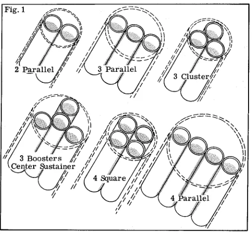
(5) Technical Report TR-2 Multi-Staging. ®. By Vernon Estes. These reports are published as a service to its customers by Estes Industries, Inc., Box 227, Penrose, Colorado 81240. Multi-staging is one of the most prominent characteristics of modern rocketry. The technique is used with solid propellant rockets and liquid propellant rockets, in rockets less than a foot tall and in rockets which tower to over one hundred feet. Multi-stage rockets are used to send up payloads from ants to humans to 500 feet, into orbit, and on to other planets. The performance necessary for high orbits, moon shots and interplanetary probes is provided by multi-stage rockets. The principle advantage of multistaging is the elimination of unnecessary weight in the later portions of the rocket’s flight. For example, compare two rockets weighing 1500 pounds at takeoff, one a single stage missile and the other a two-stage rocket. The single stage rocket holds 1000 pounds of fuel inside a 500 pound body while the two stage rocket consists of two 250 pound bodies, each carrying 500 pounds of fuel. When half the fuel in the single stage rocket is used there is still another 1000 pounds for the remaining half of the fuel to carry. On the other hand, when half the total fuel load of the two stage rocket is used, the stages separate leaving 250 pounds of dead weight behind with only 750 pounds for the remaining half of the fuel to move. This weight saving is even greater at burnout when the single stage rocket weighs 500 pounds and the multi-stage rocket only 250. high pressure is built up in the area between engines. This pressure will force the stages apart. Second, the nozzle of the upper stage engine is quite small making a difficult target for the hot gases and burning particles. Also, the nozzle of the upper stage will cool gases slightly as they enter it.. The principles of model rocketry and professional rocketry are identical although the model rocketeer uses somewhat different operating methods than the professional. The young rocketeer who masters the principles of multi-staging is gaining knowledge which he will find useful in his future career.. These problems in multi-stage ignition led to an extensive research program at Estes Industries. Revisions in engine design, gimmicks such as pressure relief vents, etc., were tried, but none proved satisfactory. What was needed was a method of controlling stage separation so that the hot ignition gases would have a proper chance to act on the upper stage engine before the upper and lower stages parted company,. IGNITION The lower or first stage of a multi-stage rocket is always ignited by standard electrical means. For further details, refer to the instruction sheet which is included with all rocket engines. The second stage ignition is accomplished automatically upon burnout of the first stage. As you will notice in figure 1A, the first state engine has no delay or ejection charge. This is to assure instant ignition of the following stage upon burnout.. After data on several hundred-test firings had been collected, the problem was reanalyzed to find the factors which contributed most to reliability. There were two: An extremely tight joint between stages and a coupling which forced the two stages to move apart in a completely straight line.. In figure 1B the propellant has been partially burned leaving a relatively large combustion chamber. As the propellant continues to burn, the remaining wall of propellant becomes thinner and thinner until it is too thin to withstand the high pressure inside the combustion chamber. At this point the remaining propellant wall ruptures, allowing the high pressure inside the combustion chamber to exhaust forward toward the nozzle of the next stage, carrying hot gases and small pieces of burning propellant into the nozzle of the second stage engine. This action is illustrated in figure 1C.. The simplest, most reliable method of joining stages tightly was immediately considered - tape. By wrapping one layer of cellophane tape around the joint between engines and then recessing this joint 1/2” rearward in the booster body tube, as in Fig. 2, reliability suddenly jumped to almost 100%. Thus it was discovered that the coupling system played the most important part in multi-stage ignition reliability.. For this system to work, the rocket must be designed and built to make the best use of the operation of the engines. If the upper stage engine is simply placed ahead of the booster engine so that the two can separate easily, ignition reliability may fall as low as 40 percent, depending on the type of booster used. This unreliability in ignition is the result of several causes. First, when the forward propellant wall of the booster burns through,. 3.
(6) STAGE COUPLING The procedures used for two stage rockets should also be used on rockets with more stages. It is important, however, to get considerable experience with. We have already seen that the stage coupling must be tight and must allow the stages to move apart only in a straight line directly away from each other. This is to gain control over stage separation, preventing premature separation and incomplete separation. To understand just how tight this joint must be, wrap a single layer of 1/2” wide cellophane tape tightly around the joint between two engines as in Fig. 3A. Then, grasping each engine firmly as in Fig. 3B, pull them apart. If you repeat this a few times you will develop a “feel” for stage coupling which will prove very valuable when you build and fly multi-stage rockets.. two stage rockets before attempting to design a 3 or 4 stage model. Rockets using large diameter tubes (BT-50 and BT-60) require somewhat different methods, but the same principles of tight coupling and straight-line separation must be followed. The recommended coupling method for larger diameter tubes is illustrated in Fig. 6. The stage coupler is glued to the booster body tube, with the adapter for the upper stage engine mounting positioned forward to allow the stage coupler to fit into the upper stage, while the tube adapter in the booster is positioned to the rear. The proper coupling system to use in a rocket will depend on the size of the body tube. The coupling system for rockets using tubes of approximately 3/4” diameter (BT-20) is shown in Fig. 4. With this system the upper stage engine must project at least 1/2” rearward into the booster body tube to provide straight-line separation. The engines are taped together before being inserted into the rocket. Check carefully before and after taping to be sure the engines are in their proper positions (nozzle of upper stage engine against top end of booster engine). Failure to check carefully can be highly embarrassing as well as damaging to the rocket. When the engines are taped together they can be inserted into the rocket. Wrap masking tape around the upper stage engine at the front and near the rear as in Fig. 5 to give it a tight fit in the body and push it into place. Then wrap the booster engine and push the booster into position. Failure to get the upper stage engine in place tightly enough will result in the recovery system malfunctioning, while failure to get the booster on tightly can result in its dropping off under acceleration, leaving the entire engine unit dangling from the upper stage while the rocket loops around in the air.. 4. ®.
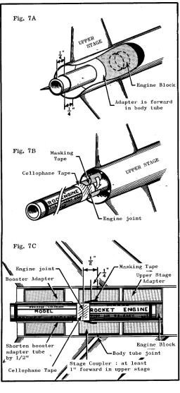
(7) The most satisfactory method of mounting engines in rockets with large diameter tubes involves positioning the upper stage engine holder tube to project 1/4” rearward from the end of the main body and positioning the engine block so the engine projects 1/4” rearward from the end of the engine holder tube (see Fig 7). This allows the engine to be held in place in its mounting by wrapping a layer of masking tape tightly around the end of the tube and the engine as in Fig. 7B. The engine mounting in the booster must be built to leave space for this engine mounting (see Fig. 7C).. With any coupling system, certain rules must be carefully followed. Engines must be held in their respective stages securely. Engine blocks must be strongly glued. Engines may be secured in their body tubes by (1) wrapping tape around the middle of the engine until it makes a very tight friction fit in the body as in Fig. 9A, (2) taping the end of the engine to the engine holder tube as in Fig. 9B, or (3) by a combination of wrapping the engine with tape and properly positioning engine blocks as in Fig. 9C.. Normal procedures call for taping the engines together with cellophane tape before mounting in the rocket. By doing this a better coupling is achieved. Figure 8 illustrates a slightly different method, recommended for use with Series I and Series III boosters only. Applying tape to the outside of the rocket is easier than taping the engines, but is also poor aerodynamic practice.. When the forward wall of propellant in the booster ruptures and hot gases blow forward, the joint between the engines is pressurized. If the rocket has been constructed with proper care and the engines mounted carefully, the tape that holds the stages together will break, allowing the stages to separate, but not until the upper stage has ignited. If proper care is not exercised, almost anything can happen.. 5. ®.
(8) This is because the booster alone is “nose-light”, since its center of gravity is fairly close to the stage’s rear. The booster should be built so that the center of the area of the fin (its balance point) matches or is up to 1/4” ahead of the booster’s balance point with an expended engine casing in place. Thus boosters will require no parachute or streamer, but will normally tumble, flutter or glide back to the ground. If the booster is to be used again, it should be painted an especially bright color, as it does not have a parachute or streamer to aid in spotting it once it is on the ground.. STABILITY Multi-stage rockets, like single stage rockets, are stabilized by air currents acting against the fins (see technical report TR-1). Since two or more engines are mounted near the rear of the rocket, it has a tendency to become tail-heavy. To compensate for this rearward movement of the center of gravity, extra large fins must be used on the booster or lower stages. As a general rule, the lower set of fins on a two-stage rocket should have two to three times the area of the upper set. Each additional stage then requires even greater fin area.. TYPES OF ENGINES. When checking a multi-stage design for stability, test first the upper stage alone, then add the next lower stage and test, and so on. In this manner the builder can be sure that his rocket will be stable in each step of its flight, and he will also be able to locate any stage which does not have sufficient fin area. Always check for stability with engine in place.. Lower and intermediate stages always use engines that have no delay and tracking charge and no parachute ejection charge. There is no delay so that the next stage will receive the maximum velocity from its booster. The engines which are suitable are those which have designations ending in zero, such as the C6-0 and D12-0. The selection of booster engines will depend on several factors, including the rocket’s stability and weight, launch rod length, and weather conditions. Generally heavy rockets and rockets with large fin area should use B6-0 or C6-0 booster engines unless there is no wind blowing. Experience has shown that even a gentle breeze is enough to make these models weathercock severely, resulting in a loss of altitude and a long chase after the rocket. This is especially so when engines other than those mentioned are used. In the upper stage an engine with a delay and tracking charge and parachute ejection charge is used. As a general rule the longest possible delay should be used as multi-staging imparts considerably more velocity to the final stage, and the rocket must have an opportunity to lose this velocity before the parachute is ejected. Greater altitude will be obtained and damage to the recovery system avoided in this manner. Engines suitable for upper stage use are those with long delays such as the B6-6 or C6-7.. MULTI-STAGE - BUILDING AND FLYING Before attempting to build a multi-stage rocket, the rocketeer should build and fly several single stage rockets to familiarize himself with the principles involved. The reliability of a two stage rocket is always less than a single stage rocket, and as more stages are added the reliability drops even farther. Hence, more building and flying skill is required as the rockets become more complex. Fins must be securely glued on multi-stage models and especially on booster stages since considerable pressure is applied to the fins at stage separation. It is usually a good idea to put launch lugs on both the upper and lower stages of a multi-stage vehicle. Special attention to other details of rocket construction, including attachment of shock cords, nose cone fit, and alignment of fins is also quite important.. To obtain the maximum stability from the fin area, care should be taken in construction to create an aerodynamically “clean” shape. The transitions between stages should be as smooth as possible to prevent interrupting the airflow and causing turbulence.. BOOSTER RECOVERY. When flying multi-stage rockets, extra caution should be taken to select a field that is free of dried weeds, grass, or other highly combustable materials. The field should be at least as wide and as long as the maximum altitude the rocket is expected to reach. There should be no persons in the area who are not observing the rocket flight.. Most lower stages are designed so that they are unstable after separation.. Multi-stage rockets should be flown only in reasonably calm weather, as they have an extreme tendency to weathercock. When the rocket is placed on the launcher, care should be taken to assure that the alignment of the stages is not disturbed. Observers should be assigned to follow each individual stage to prevent the loss of part of the rocket. General safety precautions such as adequate recovery systems, not launching when planes are overhead, and others which are normally taken with single stage rockets should also be taken with multi-stage rockets. Attention to safety rules makes rocketry activities considerably more enjoyable and educational.. 6. ®.
(9) Technical Report TR-3 Altitude Tracking. ®. Estes Industries 1963. These reports are published as a service to its customers by Estes Industries, Inc., Box 227, Penrose, Colorado 81240. Single Station Tracking. At the firing range, A is found by the tracker when he locks his scope at the rocket’s peak altitude. If we know the distance from A to C, or side b of the triangle, we can find side c and side a. Side a is the one in which we are interested. It is the height of the rocket. This of course assumes that angle C is a right angle.. Every rocketeer asks the question: “How high did it go?” However, previously, few model rocketeers had the facilities to determine altitudes with any reasonable degree of accuracy. Some have attempted to find the altitude achieved by their rockets by the use of a stop watch, but this method is so highly inaccurate that the computed altitude may fall anywhere within 200% of the actual altitude. Several years of experience among model rocketeers have proven that optical systems are the only practical means for finding altitudes with any reasonable degree of accuracy.. If we only use one tracker, we have the problem of knowing only one angle and one side. This is not enough information to solve the other sides of the triangle. However, we can guess at one of the unknown angles, and obtain a good approximation of the height achieved by the rocket. If only one elevation tracker is used, it is a good idea to station it at a right angle to the wind flow. For example, if the wind is blowing to the west, the tracker should be either north or south of the launcher. In this way we will keep the angle at C as close to a right angle as possible. By experimenting with a protractor and a straight edge, the rocketeer can demonstrate why the error would be less if the tracker is on a line at a right angle to the flow of the wind.. The use of an optical tracking system requires the use of mathematics. The particular field of mathematics which is used the most in altitude computation is trigonometry. While this field is normally considered an advanced high school subject, any rocketeer can master its basics and apply them to his rocketry activities. If the rocketeer masters a few simple processes, he is ready to solve almost any problem in altitude computation. One of the first principles of trigonometry is that all of the angles and sides of any triangle can be found if any three of its parts, including one side are known. Every triangle has six parts: Three angles and three sides. If we know two angles and one side, we can find the other angle and the other two sides. In determining the height of a rocket we collect two types of data: distances and angles. This data is used to create a triangle which is a model of the lines which would join the tracker and the rocket, the rocket and a point directly below it on the ground, and the point on the ground and the tracker.. In the diagram above, the wind is blowing from B to D. The rocket is launched at point C, weathercocks into the wind, follows approximately line CA, and at its maximum altitude is at point A. If the tracker is downwind from the launcher, he will see the rocket at point F and compute the altitude as the distance from C to F. His computed altitudes will be considerably lower than the true altitudes. On the other hand, if the rocket drifts toward him, his computed altitude will be considerably higher than the true altitude.. In the diagram above, point A represents the tracking station, B the rocket at its maximum altitude, and C a point on the ground directly below the rocket. The angle formed by the lines at C is then a right angle or 90 degrees. Since there are 180 degrees in the angles of a triangle, if we know angle A, we can find angle B, since B = 180 degrees - (A+C), or B = 90 degrees - A. (In trigonometry, a capital letter represents an angle, a small letter represents a side. The small letter “a” will always be used to represent the side opposite angle A, “b” the side opposite B, etc. Two capital letters together represent a distance. Thus BC represents the distance from angle B to angle C, or side “a”.. However, if the tracker is at point X in figure 3 and the launcher at Y, then the rocket will appear to be at point A as in figure 1, although the distance from the tracker to point A will be slightly greater than the baseline used in computing the altitude, the error will not be nearly as great. Also, the small additional distance will serve to make altitude readings more conservative, as the baseline will be increased.. 7.
(10) Summary (1) In single station elevation tracking, we make sure that the line from the tracking station to the launcher in 90 degrees from the direction of wind flow. (2) The angle of flight is assumed to be vertical. (3) The tracking scope is locked at the rocket’s maximum altitude, the angle read, and the tangent of the angle found. (4) The tangent is multiplied times the distance from the tracker to the launcher, giving the rocket’s altitude.. By observing the proper relation between wind direction and the position of the tracker, we can generally determine with 90 percent or better accuracy the altitude the rocket reaches from data given by only one elevation tracker. Of course, the closer the rocket flight is to the vertical, the more accurate will be the figures obtained. Therefore, on a calm day with a good model, we can approach almost perfect accuracy. The method used to determine altitude with one tracker is outlined below. Bear in mind that this system assumes that the flight will be almost vertical, if not completely vertical. The rocketeer would do well to master this system before going on to more complex systems, as this method is used as a part of the more involved procedures.. Two Station Tracking A higher degree of accuracy is possible when two elevation tracking stations are employed. In such a case, we will have triangles with 2 angles and one side given, enabling us to determine the other parts of the triangle without guesswork. When using two trackers without azimuth readings the tracking stations are set up on opposite sides of the launcher. Preferably, to obtain the greatest accuracy, the stations should be in line with the wind, unlike the system used in single station tracking. Thus, if the wind is blowing to the south, one station will be north and the other south of the launch area. The distance between the two trackers is not critical. One might be 100 feet from the launcher and the other 500 feet away. However, for the greatest ease in data reduction, the distance should be equal. For the greatest accuracy, they should be as far apart as possible. A general rule is that the distance from the stations to the launcher should be equal to or greater than the maximum altitude the rocket is expected to achieve. Some provision should be made to insure that the trackers lock their instruments at the same time. This is one of the greatest problems with any system using more than one station: The one tracker may lock his scope when the rocket appears to him to have ceased rising while the other tracker is still following the rocket. If a phone system is used, one of the trackers or a third party should call “mark”, and the trackers should lock their scopes immediately. In the system described here this is especially important, as the elevation readings from the two trackers must be taken at the same point or the altitude computed will be somewhat incorrect.. If we assume that the rocket flight is vertical, we can call C a right angle (90 degrees). In that case, B is equal to 90 degrees - A (the sum of the angles in a triangle is 180 degrees, half of this or 90 degrees taken by angle C). Then to find the distance from C to B or the height the rocket reached we take the tangent of angle A (abbreviated tan) times the distance from the tracker to the launcher (side AC of the triangle). For example, if the distance from the tracker to the launcher (baseline) is 250 feet and the angle observed by the tracker at the rocket’s maximum height is 62 degrees, we will look in the table of trigonometric functions and find the tangent of 62 degrees. The tangent in this case is 1.88, so we multiply 1.88 times 250 to find our altitude, which is 470’. Altitudes for model rockets are normally rounded off to the nearest ten feet. If the calculated altitude had been 332 feet we would have rounded it off to 330 feet.. In this more accurate system we will work with sines instead of tangents. To determine altitude, then, we will first have to find the unknown sides of the triangle, as we have no right angles to work with. For example, stations A and B are located on a 1000’ baseline with the launcher between them. Station A calls in an elevation of 34 degrees, and station B calls in an elevation of 22 degrees. The total of these two angles is 56 degrees, so angle C, located at the peak of the rocket’s flight, is equal to 180 degrees - 56 degrees, or 124 degrees. We now have 3 angles and one side to work with. Our first step will be to list the angles and their sines. Since the sine. Why do we use the tangent to determine altitude? The tangent of an angle is the ratio of the opposite side to the adjacent side, or in other words, the opposite side divided by the adjacent side. In this case, the adjacent side is the distance from the tracker to the launcher, and the opposite side is the distance from the launcher to the rocket’s maximum altitude.. 8. ®.
(11) However, if we can combine the formulas to make one formula, we can speed up our work considerably. Now c x Sin A = A, so we can SinC c x SinA ) for a in the formula a x SinB = CD. substitute the experssion ( ––– SinC c x SinA x SinB = CD. One of the basic Our formula then becomes –––– SinC rules of algebra tells us that if the dividend is multiplied by a number and the result divided by the divisor, the result is the same as if the division were carried out first and the quotient multiplied by the number. For example, 10 x 4 = 8, and ––––– 5 10 x 4 = 8. ––––– 5 We can change the expression c x SinA x SinB = CD to read SinC c x SinA x SinB = CD. So by performing two multiplications and one ––––––––––––––– SinC division, we can find the altitude of the rocket. The division of SinC into the experssion (c x SinA x SinB) can occur at any point, as c x SinA x SinB = CD, –––––––––– SinC and c x SinA x SinB = CD also. ––––––––––– SinC. of any angle greater than 90 degrees is equal to the sine of the supplement of the angle, the sine of 124 degrees is equal to the sine of 180 degrees - 124 degrees, or 56 degrees. Angle A = 34˚ Sine A = .5592 Angle B = 22˚ Sine B = .3746 Angle C = 124˚ Sine C = .8290 The law of sines states that. c SinC. =. b SinB. =. This last form of the equation will give the same result as the first, and actually involves the same steps, but is generally easier to use.. a SinA. Summary. c = 1000’, sinC = .8290 Therefore, 1000 = b a –––– –––– = ––––– .8290 .3746 .5592. 1. In two station tracking without the use of azimuth readings we station the trackers on a base line approximately equal to twice the altitude the rocket is expected to reach.. 1000 We calculate that ––––– = 1205. We have .8290 a dividend, divisor and quotient. In solving for side b, our dividend is b, our divisor .3746, and our quotient 1205. To find the dividend we multiply the divisor times the quotient. Now .3746 times 1205 = b, and b = 451. The same process is repeated to find side a: 1205 = a, a = 1205 x .5592, a = 674’. We now have the three sides of the –––– .5592 triangle.. 2. The trackers are located in line with the wind. 3. The scopes are locked at the rocket’s maximum altitude, the angles read, and the sines of the angels found. 4. The altitude is computed by the formula height = c x SinA x SinB SinC when A and B are the angles read by the trackers, c is the baselie distance, and C is the third angle formed by the meeting of the lines of sight of the two trackers.. The altitude of the rocket is then the distance from C to D in the diagram above. The angle formed by the meeting of lines AB and CD is a right angle. Since the sine of an angle in a right triangle is the relation of the opposite side to the hypotenuse, and since we wish to determine the value of the opposite side, a we find that the sine of A (34˚) is . 5592. Hence .5592 = ––– , 451 opposite side SinA = ––––––––––– hypotenuse. . .5592 x 451 = 252, CD = 252’ . We now know the altidude reached by the rocket was 252’.. since. Fortunately, our computations to determine the altitude of the rocket can be simplified. To find the altidude we need only determine one of the unknown sides of the original triangle. If we find the distance BC (side a) on the triangle, we can multiply it times the sine of B to find the height CD. c a c –––– = ––––– Since we have found –––– equal to 1205 SinC SinA. SinC a when C = 124˚, ––– = 1205. Then 1205 x SinA = SinA So. side a = 674’. Now we have the one needed side of the triangle, so we can solve for distance CD in the right triangle BCD. The sine on an angle is equal to its opposite side divided by the hypotenuse. We take the sine of B, which is .3746, times the hypotenuse, or 674’ to find the opposite side CD. Thus, .3746 x 674 = 252’.. For angles of 81˚ through 89˚ the sine is .99, the sine of 90˚ is 1.00. Tangents over 80˚ are not given, as no sensible data reduction is possible for angles that great.. The complete series of computations then would be–––– c x SinA = a, and SinC a x SinB = CD.. 9. ®.
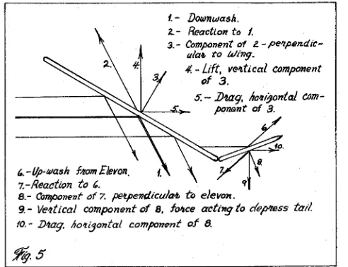
(12) Technical Report TR-4 ®. Rear Engine Boost-Gliders Estes Industries 1963. By Gordon Mandell. These reports are published as a service to its customers by Estes Industries, Inc., Box 227, Penrose, Colorado 81240 case of rocket stability is one in which very little corrective moment is applied because the rocket flies with little oscillation directly into he relative wind. While the air hitting the surfaces of an angle produces a component of force acting perpendicular to the body to push the rocket back into parallel with the. Introduction: These are the preliminary findings of a research program conducted since March of 1962. Some fifty boost-glide vehicles have been constructed to date. To augment the findings, library research in aerodynamics has been conducted. Keep in mind that these findings are of a mainly qualitative nature, with expected accuracy in most other case (i.e.; quantitative findings) about plus or minus 10%, except as specified. I. The Boost Phase: A boost-glider is a model rocket which rises vertically in the manner of an ordinary fin-stabilized rocket, and returns in an aerodynamic glide. It is an aircraft and a rocket in one. Let us investigate the design requirements for. a vehicle of this type. The first thing we must bear in mind is that we are designing a rocket, which is stabilized by locating the center of pressure behind the center of gravity in the manner detailed in Technical Report TR-1. This is going to have an obvious effect on the boost-glider. Its wings must be located so that they bring the CP of the top view behind the CG by a substantial margin, and also its directional stabilizing surface, the rudder(s) must be located so that it brings the CP behind the CG in the side view. The distance between the CG and CP is called in physics a moment - arm, and the stabilizing force exerted by the moment arm, results in the corrective moment. This moment is, obviously, proportional to the force of the air hitting the surfaces, which in turn is dependent on two factors: The speed of the rocket and the angle that its longitudinal axis (body) makes with the relative wind. The ideal. relative wind, it also produces a component of force pointing directly rearward from the rocket, and parallel to the relative wind. This latter force is drag, and the more the rocket oscillates, the greater will be both corrective moment (if the rocket is stable) and drag. Because of its large surfaces, it is best to design the boost-glider so that its stability is greater than the needed for most other rockets. Generally the center of pressure should be at least 3/4 the body diameter behind the center of gravity.. II. The Glide Phase: In glide phase, most rear engined boost-gliders use what is known as the flatplate effect. (A fully symmetrical airfoil may be used, but it involves some difficulties in construction and alignment. The principles involved in this type of airfoil may be studied in most books covering aerodynamics.) The flat-plate effect simply makes use of the relative wind bouncing off the wing, which produces a component of force which is perpendicular to the wing (see Fig. 5). Since the wing is tilted at an angle to the relative wind, the force will also be tilted at this angle. Thus, when resolved into components parallel with and perpendicular to the relative wind, drag and lift, respectively, are determined for the wind surface. For any lift to be produced in this manner, the wing must be inclined upward into the relative wind. This is accomplished by means of flaps located at the rear of the wind (in a delta or flying wing design), commonly called elevons. These elevons are tilted up at the rear, which means, by our previously stated principle, that air hitting these elevons will force the rear of the wing down. This, in turn, means that the forward end of the glider is forced up, meeting the relative wind at an angle, and the vehicle glides. Obviously, the extent of this force, called the moment of tail depression, is dependent on the speed of glide, the angle at which the elevons are set upward, and the size of the elevons. To discover what size of elevon is best for a given glider, we must first take into consideration that there must be some force which makes the glider travel forward in the first place. In glide phase, the engine has been expended, and the only forces acting on the glider are those of air and gravity. After the rocket reaches flight apex and expels its engine, it begins to fall towards the earth. This produces a relative wind which is directly opposite to the direction of travel, i.e.; the rocket is falling down so the relative wind will be up (see Fig. 3). In almost every design imaginable, the CP will remain behind the CG after. 10.
(13) ejection of the engine. As a matter of fact, many designs experience a forward shift of CG as the engine ejects. Thus, the glider remains stable as a rocket, and with its corrective moments still effective, the nose turns toward the ground. However, since the elevons have been actuated by this time, the rear of the rocket is forced down by the air acting against them, and thus the nose is forced up and the flat-plate effect suspends the vehicle in gliding flight. In order to glide, the rocket corrective moment must be overcome by the flat-plate effect of the elevons. Since setting the elevons up at an angle also produces drag, the boost-glider will, in glide, reach a terminal velocity of forward motion and will then keep this velocity rather constant. So we now know that our elevons, to be effective, must produce a depressive force greater than the rocket’s corrective force at the terminal velocity of glide. With these factors in mind, then, we can see that the size of the elevons required depends on: (1) the distance between the CP and the CG of the top view in glide and (2) the velocity of the vehicle in glide. The latter is itself dependent upon the size and the angle setting of the elevons, being from about five to fifteen miles per hour in the average glider. For a glider of approximately one half to one caliber rocket stability in glide phase and which has elevons located at the rear of the wing at an average distance from the CG, elevons of approximately 20 to 30 percent of the total wing area are needed for a good, easily adjustable glide. This amount will vary down to about 10% for less stability in glide phase than in powered flight and up to about 35% for greater stability in glide phase. Any glider requiring more than 35% is not properly designed, and probably possesses an engine located very far to the rear for excessive rocket stability.. There is no definite rule as to the best aspect ratio for delta or flying wing designs. It seems that high aspect ratio wings give faster response to thermal currents than low aspect ratio wings. Low aspect ratio wings are slower to recover from dives. However, structural considerations also come into the picture, as we shall see in Part III. Just about any rudder large enough to give stability as a rocket in a side view is sufficient to directionally control the vehicle in glide. It has been noted, however, that a glider is more susceptible to spiral diving during turns when its center of directional guidance (the center of lateral area of the rudder) is more than 3/4 caliber behind the center of lift (the center of lateral area of the wing in flat-plate airfoil models). This has been found to be at least partially caused by a flow of air crosswise on the forward part of the wing, allowing excessive side slip and turning, which results in a spinning, nose-down attitude. A boost-glider will have better resistance to rolling in glide when its center of directional guidance lies above the CG, as when the rudder is located on top of the body tube. There are yet no definite rules for wing-tip rudders and for dihedral angle of lifting surfaces. However, it is known that dihedral angle in moderate amounts improves glide by giving a “pendulum effect” while it does not detract noticeably from rocket performance. The glider need not be symmetrical in side view, as are most rockets.. An interesting variation on elevon-controlled gliders is the canard design. Canard gliders may be constructed in several ways. First, an explanation of “canard” might be in order. A canard is defined as any lateral stabilizing surface (that is, one that prevents pitching) located forward of the main lifting surface. Canards may also provide lift. When equipping canards with flaps, we must remember that, since the canards are forward of the CG, to induce the nose to angle upward we must deflect air downward by means of our canard-mounted elevons. Therefore, while we build rear mounted elevons to flip upwards at engine ejection, we must construct canard flaps so that they flip downwards at this time. Construction of mechanisms or various types of flap actuation will be covered in Part III. One advantage of canard flaps is that, besides inducing an inclination to the relative wind of the main lifting surfaces, they also provide a small amount of lift themselves, since they deflect air downward and by the principle of action and reaction are acted upon by this air in an upward direction.. Another factor to be considered in designing boost-gliders is wing loading. This figure is widely used in professional engineering, and is arrived at by dividing the area of the lifting surfaces by the weight of the vehicle in glide condition (without engine). The higher the wind loading, the greater will be the rate at which the glider descends during glide. Obviously then, one way to attain a good glide is to use wings as large as possible and body tubes as light as possible. However, this too is subject to structural limitations. Increase in lift may also be obtained by increasing the angle of attack to the relative wind. However, this also increases drag, and past a certain point drag slows the vehicle to the point where lift begins to decrease again. III. Structural and Flying Practice: It would indeed be gratifying if we could use as high aspect ratios, as large surfaces, and as light construction as its dictated by ideal theory. Unfortunately, structural practice is controlled by the forces which a boost-glider must withstand in flight, and the dictates of these stresses often run opposite to those of theory.. Designs which have only canard-mounted elevons usually are of rather high aspect ratio (the aspect ratio is the wing span divided by the average wing width, or chord) than other designs, and experience a slight rearward shift of CG after ejection. Since they have a longer moment-arm through which to act, canard flaps usually do not need to be as large as the flaps in other designs. Canard designs offer slightly more drag then others and are all but useless when the nose is very heavy, since this shortens the moment-arm through which the flaps can act. Very successful canard designs have been constructed with elevons on both the main wing and on the canards, connected by thread to each other. However, these also suffer when the nose is heavy and consequently must be built with very light noses.. The extent of these forces, caused by acceleration and air drag, is dependent upon the size of engine used and the number of engines or stages. The greater the acceleration and the duration of that acceleration, the greater the speed and hence the drag. In first considering the forces acting. 11. ®.
(14) on the aerodynamic surfaces at constant acceleration, the force will vary as the square of the velocity, as stated in the equation for drag. In general, a balsa thickness of 1/16” has been found adequate to withstand all air forces produced by Series I engines, provided the aspect ratio of the wing or other surface does not exceed about 4; that is, if the span of the wing divided by the width, or chord, does not exceed this number. Above this number, the wind begins to twist the surface, producing the same effect as warp.. An even better alternative involves the use of an expended engine casing to shift weight forward. The nozzle is drilled or chipped out of the old casing and the casing is then glued or taped to the front of a live engine. Thus, when the engine is ejected, it will take the expended casing with it, lightening the nose for a good glide. This method gives much greater boost stability. The current world’s record holder of glide duration was equipped in this manner. For the early recessed-engine models, and for multi-staging, it has been found necessary to arrange some system by which the depressor bars will not interfere with the stage joint. Obviously, a system using depressor bars which extend rear of the body tube to be operated by an engine which sticks out of the rear of the tube is impossible in recessed engine models, and interferes with mating of the stages. Instead, ports are cut in the body tube forward of the elevons, and the depressor bars are operated through these ports. This adds to drag and is more difficult than external-bar arrangements, but is the only proven method of meeting these special requirements. This method is also used to operate canard flaps, which are located far forward on the body. Ports too near the front of the engine casing have caused ejection failure. In general, ports should not be cut less than about 3/4 inch to the rear of the point where the forward end of the engine casing will rest in flight. In this way, pressure does not escape from the ports at ejection charge activation.. Also of importance is the effect of acceleration during boost. A one-ounce model’s wings may weigh 23 times their normal weight for a short time during boost. For this reason, wings should be kept as light as possible consistent with adequate aerodynamic strength. Also, wings which have their CG closer to the body tube, or with low aspect ratios, will be more resistant to being torn loose from the body tube by acceleration forces. The strongest wing-body joints are possible when the wings are joined together with each other and the body at the underside of the body and the connection reinforced by 1/2 inch wide strips running parallel to the body at the joint. The grain on these strips should be at a right angle to the end by the use of gauze or silk reinforcing, by using thicker balsa for the wings, and by using the longest practical wing-body joint. Internally-operated elevon actuators, such as pistons driven by the ejection gases, have been tried, but have been found to be not as reliable and more difficult to construct than those actuated by the ejection of the engine. The simplest system to employ is one in which a piece of wire or balsa is held depressed by the engine casing. When one end of the actuator is held in place by the engine, the other end of the stiff wire or balsa is attached to the elevon, so that the elevon is in neutral position with the casing in place. A piece of elastic thread is fastened to the elevons in a manner which will pull them up (or canard flaps down) when the engine leaves the body tube and allows the wire depressor bar to travel to the actuating position (see Fig. 9). When the depressor bar runs rearward from the elevon to the casing, it should be held down by the casing; when forward it should be held upward by the casing, which will push the elevon down to neutral.. Elevons in the rear and canard flaps in the front can be operated together if the rear elevon actuator is made according to standard practice, and then strands of ordinary thread are attached to the elevons, as far to the rear as possible. The thread is then brought forward, crossed over the body tube, and attached to the canard flaps. Thus the left elevon will, when released, lower the right canard flap, and the right elevon the left canard flap. The canard flaps are, of course, equipped with elastic thread to pull them down when the thread is slackened, which happens when the rear elevons are actuated. Gliders using this system can be made to stay in the air for more than two minutes, single staged.. Systems have been tried in which the arrangement is one continuous bar fastened to both wings, and where there are two bars, one for each wing. The latter has been found to be more practical, as it allows individual setting of each elevon. Setting is accomplished either by a small balsa brace with a set screw which, depending on how far the screw is turned up or down, will regulate the elevon accordingly, or by a single-strand, soft copper wire, which can be bent to the degree of elevon desired, and will stop the eleven’s upward travel depending on how far it is bent.. Research on cluster-engined boost-gliders has so far shown that they are not as practical to build and fly as single-engined gliders, due to the large concentration of weight at the rear of the body. This requires that rocket stability be increased by placing the wings very far to the rear, with the result that the CG moves forward a considerable distance at the ejection of the engines. This in turn makes extremely large elevons a necessity. CONCLUSION: The design and construction of good boost-gliders is still an art and requires a high degree of skill in the modeler. But there are few things in any area of modeling which can compare with the satisfaction of building and flying a good glider. This is a field with a genuine challenge for the builder and those who accept the challenge will find themselves plunged into a search for new methods, materials, and principles that results not only in an expanded knowledge of the physics of flight, but also in contributions to the entire art of model rocketry.. With early types of gliders, in many cases the engine was set forward of the aft end of the body tube to move weight forward further. This, after a number of firings, tended to burn away some of the body tube. This was corrected by the application of a solution of sodium silicate (waterglass), a chemical used as a flameproofer and egg preservative, to the inside rear of the body tube. Waterglass has the disadvantage of blistering and ablating into the exhaust gases, leaving a flaky residue and unsightly appearance, as well as impairing the fit of the engine into its mountings. For applications involving the protection of elevons or rudders from exhaust gases, aluminum oil was found much more satisfactory, the foil being glued to the surface in question.. 12. ®.
(15) Technical Report TR-5 Building a Wind Tunnel. ®. Estes Industries 1963. These reports are published as a service to its customers by Estes Industries, Inc., Box 227, Penrose, Colorado 81240. Building a Wind Tunnel. Published by Estes Industries, Box 227, Penrose, Colorado ©Estes Industries 1965. 13.
(16) 14. ®. 2”x 4”. 3/4” x 12” x 43”. 11 1/4” I.D.. Approximate wind velocity 22 feet per second.. 10”. 2”x 4”. 3/4” x 12” x 43”. 11 1/4” I.D.. 2”x 4”. Designed and developed by Vernon Estes 1961 Scale: 3” = 1’. Estes Wind Tunnel. Bottom Pc. 3/4” x 12” x56”. Screen suppressor placed into tunnel 14 1/2” from 1/4” Window Channel blower outlet.. 1/4 round moulding used on both sides of screen, since considerable pressure develops here. (See side view - 1/2” moulding used on original.). tubing used on original.). 11 1/4” x 12” Plexiglas. 3/4” x 12” x 31” Front Pc.. 4. This shows how 52 pieces of BT-60 are installed to muffle turbulence and direct the flow of air. (Note: 1 3/ ” aluminum. OBSERVATION - END VIEW.
(17) 8”. 4”. FRONT. 3/16”. REAR. Minimum Friction Calipers. piece 1/8” welding rod, 28” long pieces aluminum bar stock 3/16” x 8” x 3/4” acoustical phonograph needles bolt and wing nut (optional) thumb screw. Bill of Materials: 1 2 2 1. Cutaway shows depth to drill for needle seat.. FRONT. 3/4”. Tap in threads. REAR. If thumbscrew is used, drill one bar with drill at least one size smaller than the other to allow threads to be tapped. See inset.. Drill to size of bolt or thumbscrew. (Useful accessory in determining C.G. and stability of your model rocket.). 3/8”. 11 3/8”. Rod can be bent around a coffee can to get a smooth radius curve.. ®. 15.
(18) 16. ®. 12”. 7”. 12”. 4”. 11 1/4”. 1/2”. 5”. 1/2”. Scale: 2” = 1”. SIDE VIEW. 15”. 34 1/4”. COMPRESSION CHAMBER. Screening set in 1/4-round moulding cut to inside Tunnel dimensions. 31”. 2”x 4” legs and cross-pieces. 53”. BT-60 11”. Straightener. Air-Flow. 43”. 56”. 1/6 to 1/2 H.P. Motor. Any “Squirrelcage” Blower with 11” or 12” Square Outlet..
(19) 17. Nail four pieces of quarter round moulding into the tunnel to form the rear (blower end) frame for the screen as shown in the plans. Press the screen into position and nail the other four pieces. Paint the inside and outside of the tunnel with enamel paint. Be especially careful to give the inside of the tunnel a smooth finish to reduce turbulence and give a more even air flow.. The first step in assembly is to cut out the front, back, top, and bottom pieces from 3/4” plywood. These pieces should be cut out carefully so they will match up properly when attached to each other. Sand the four pieces on all sides and then nail them together to form the tunnel body as shown in the plans. Use 6d finishing nails and apply white glue to the joint before pressing the wood together and nailing. Support the tunnel body during this operation to insure that it remains perfectly square.. The blower used in this wind tunnel is a standard furnace blower, and it should be possible to obtain one from your local plumbing-heating contractor for a reasonable price if you specify a used one and tell him what you are going to use it for. The motor can be almost any 1/6 to 1/2 horsepower, 115 volt unit. The ratio of the sizes of the pulleys will depend on the output speed and power of the motor and the rated speed of the blower.. The Estes Wind Tunnel was designed especially for checking the stability of model rockets, and can be easily built by the modeler with moderate experience in woodworking. Modifications in this wind tunnel design allow the use of materials the rocketeer already has on hand should not hurt its performance to any great extent.. Wind Tunnel Assembly Instructions. ®. Make a belt guard to keep fingers out of the moving parts of the wind tunnel. This guard should be designed to fit the pulleys and belt used on your wind tunnel, and may be made from sheet metal, cardboard, plywood, or other materials which may be available. Attach the aluminum window channel at the front of the tunnel. Slide the plexiglas window into place and the wind tunnel is completed.. Put the flow straightener tubes in place in the tunnel. These tubes should have a thin wall, and either metal tubing or BT-60 may be used. When all tubes are in place the assembly should make a tight press fit inside the tunnel body. (There are several other possibilities for the flow straightener. It may, for example, be made from heavy posterboard arranged to form a rectangular grid.). Mount the blower, motor, and belt at the rear of the tunnel. The exact mounting procedure will vary with the type of motor and blower. Make sure the belt has a firm grip against the pulleys on both blower and motor.. Cut, miter, and sand the 2 x 4 pieces for the tunnel stand. Nail the stand together using 16d nails. Nail the stand and the tunnel together, then paint the stand.. Cut and drill the bottom piece to match the mounting holes of the blower and the motor. Be sure that the holes are drilled to position the blower firmly against the rear of the tunnel. The blower should be adjusted so the flow is as even as possible.. of molding into place to form the front frame. (The screen should be nailed to place without any moulding if minimum turbulence is desired)..
(20) 18. ®. Back. Screen. OF. MATERIALS:. Front Side. Top Member. Backside. Cut to fit your own pully-belt path.. Blower. Bottom Member. Planview......Scale: 2” = 1”. AND. MOTOR-MOUNTING BOLTS. PLEASE NOTE: Though this unit is ideal for stability tests, it is not recommended for checking drag. Flow-velocity is too low at 22 feet per second.. 1 - Squirrelcage Blower with 11” or 12” Outlet 1 - 110 V. Electric Motor, 1/6 to 1/2 H.P.. MISC. NAILS - WOODSCREWS - BLOWER. 1 - 3/4” x 12” x 31” ..................Front Side Member 2 - 3/4” x 12” x 43” ...................Top Member and Back Side Member 1 - 3/4” x 12” x 56” ...................Bottom Member 1 - 11 1/4” x 11 1/4” .................Standard Wire Screen, 8 mesh 8 - 1/2” x 11 1/4”.......................Quarter-round molding for frame on screen 52 - 11” Section........................B-T 60 Tubing 1 - 11 1/4” x 12” x 1/4”.............Plexiglas Sheet 2 - 1/4” x 12”.............................Aluminum Window Channel 2 - 2” x 4” x 10” ........................Top Leg-Land 2 - 2” x 4” x 19 3/4”..................Leg Cross-Brace 4 - 2” x 4” x 37 1/4”..................Leg 1 - 2” x 4” x 53” ........................Longitudinal Leg-Brace. BILL. Open End Permits Test of Larger Models… But, results may be inconclusive due to “Outside Air” mixing into straight flow, causing turbulence at varying distances from tunnel-end. Suggest nose of vehicle under test be placed well into tunnel.. Use of low-friction pivot-points is shown here, protruding through the slots adjacent to plexiglas “Window”. Model Rocket in Airstream. Joint Detail. Top. Plexiglas Panel. Cutaway shows tubes and screen placement more clearly.. Air Flow. Top View.
(21) 19. Testing Rockets for Stability. Any model rocket must be able to “recover” and point back into the wind when it is pointed 5 degrees out of line. A good general rule to follow is to require an additional five degrees of recovery for every ounce of rocket weight. When we. It still remains to determine just how stable the rocket may be. It is not enough if the rocket remains pointed into the wind when aimed in that direction, it must also be able to recover and point back into the proper direction when a rotating force such as an off-center engine or a side gust of wind interferes with the rocket’s flight. Also, a heavier rocket must be more stable than a light rocket, since the heavier rocket is going slower when it leaves the launch rod and gets less corrective force from its fins at the lower speed.. When the rocket has been balanced correctly, turn on the wind tunnel, and holding the calipers vertically as in the illustration on the previous page, insert the rocket nose first into the wind tunnel. If the rocket remains pointing nose first into the tunnel with nothing but the calipers touching it, it is stable. The string and soda straw (see TR-1) may be used in place of the calipers.. CHECKING FOR STABILITY. First locate the approximate center of gravity by balancing the rocket on a finger. Then set the rocket on a flat surface, spread the jaws of the calipers apart, and put them into position on the rocket in the area located previously. The two points of the calipers should be on directly opposite points on the body. Pick up the rocket with the calipers. If the nose of the rocket points down, set the rocket down and move the calipers ahead slightly. If the tail of the rocket points down, move the calipers rearward slightly. Continue this until the rocket balances perfectly. This balance point is the center of gravity. The center of gravity is always determined with a loaded engine in place in the rocket. A string and soda straw may also be used to balance and hold the rocket. For details on this system, see technical report TR-1 on Rocket Stability.. The first step in checking the stability of a model rocket is to locate its center of gravity. As you know from reading the technical report on rocket stability, the center of gravity is the balance point of the rocket and the point about which the rocket will rotate in the air.. DETERMINING CENTER OF GRAVITY. ®. In addition to determining the stability of all stages together, the upper stage alone, etc., it is also important to check the stability of the booster by itself as it would be after upper stage ignition and stage separation. In this case, however, we want results completely different from those for an upper stage. A booster stage should be unstable by itself. This is so that it will tumble to earth instead of streamlining in. When we pivot the lower stage on the calipers at its center of gravity, we want it to rotate freely and not point into the wind.. The procedures outlined above are also used in determining the stability of multi-stage rockets. However, some extra steps must be taken with such a model. A multi-stage rocket must be checked in all the shapes in which it will fly. Thus, a two-stage rocket is checked with both stages joined together and then the upper stage is checked alone.. CHECKING MULTI - STAGE ROCKETS. The rocket’s center of pressure should be at least 1/2 the diameter of the rocket body behind the center of gravity for proper stability. The diameter of the rocket is called its caliber, and it is common to talk about the stability of the rocket in terms of calibers. Thus a model which has its center of pressure 1/2 caliber behind the center of gravity is said to have 1/2 caliber stability.. A more accurate measure of stability can be made by locating the center of pressure (see technical report TR-1 on Rocket Stability). This is done best by marking the center of gravity on the rocket body, moving the calipers rearward on the body slightly, and placing the rocket back in the wind tunnel air stream to see if the rocket will still point into the wind. The calipers are moved backwards until the point at which the rocket no longer will point into the wind, but begins to rotate freely in the air stream is located. This point is the center of pressure, and should be marked on the rocket body.. FINDING THE CENTER OF PRESSURE. put the rocket into the wind tunnel’s air stream we want to see how far out of line we can point it and still have it swing back into line. The greater the angle from which the rocket can recover, the better it will fly. A one-ounce rocket which barely recovers from 5 degrees out of line is only marginally stable, while one which can recover from 20 degrees or more is stable enough to fly under almost all conceivable conditions..
(22) HAND-POWER for your MODEL WIND TUNNEL. ®. END SIDE Unit shown with chain removed. We urge builders to design and install an adequate chain guard.. Note rubber pads and brackets are removed, leaving pedal axle and housing as crank-handle.. BOTTOM “PEDAL” UNIT DETAILS Part of bike frame. Cut close 2” 4” 5”. 1/2” x 1” x 5” Strap Iron Drill to fit your bolts. WELD. If your wind tunnel is to be used on the firing range, chances are that electric power won’t be available to run a motor. To allow the range control officer to check any rockets of questionable stability, you might build your wind tunnel for hand power. The parts for the drive unit on the hand-powered wind tunnel can be salvaged from a used bicycle. The bearing carrier for the pedal-sprocket unit is cut from the frame, and the pedal on the side away from the sprocket is cut off completely. The mounting for the rubber blocks on the remaining pedal are removed to make a hand crank. Two pieces of strap iron are welded to the bearing carrier as in the drawing. This unit is then mounted at the rear of the wind tunnel under the blower. The sprocket on the blower can be one from the rear wheel of the bicycle, although a smaller sprocket will give a higher speed. Be sure that the teeth on both sprockets fit the chain. The chain should be adjusted to fit fairly tight around the two sprockets (about the same fit as for a bicycle). Design and install an adequate chain guard to protect the operator. 20.
Figure
+3

Related documents
The key segments in the mattress industry in India are; Natural latex foam, Memory foam, PU foam, Inner spring and Rubberized coir.. Natural Latex mattresses are
We make use of the representation in two different matching criteria, matching word images using corresponding line descriptors, and matching contour segments using sequence of
collaboration at the state and local levels to promote better understanding of the needs in our communities for effective usage of Automated Speed Enforcement programs to
Visoke koncentracije ortofosfata, kao što su one izmjerene u rujnu u piezometrima Zelendvor (2,01 mg/L), PDS-5 (2,55 mg/L) i PDS-7 (3,5 mg/L), mogu ukazivati na onečišćenje
elasticity becomes significant at some lower quantiles of the conditional hourly wage distribution: a 1% increase in height is associated with a 1.6% increase in hourly income
• Based on intention to treat, VRET achieves more rapid responses, and higher response rates, than imaginal exposure for PTSD. • Combination VRET with pharmacotherapy has
○ If BP elevated, think primary aldosteronism, Cushing’s, renal artery stenosis, ○ If BP normal, think hypomagnesemia, severe hypoK, Bartter’s, NaHCO3,
2: There shall be a standing By-Laws Committee consisting of three members of the Organization appointed by the new President at the close of each Conference to serve through the
