doi:10.4236/ojsst.2011.13012 Published Online December 2011 (http://www.SciRP.org/journal/ojsst)
Risk Analysis Model Using UML and MADS Model
Hafida Bouloiz1, Emmanuel Garbolino2, Mohamed Tkiouat3 1
Industrial Engineering Department, National School of Applied Sciences, E.N.S.A., Agadir, Morocco
2
Crisis and Risk Research Centre, Mines ParisTech, Sophia Antipolis, France
3
Industrial Engineering Department, Engineers’ Mohammadia School, Rabat, Morocco E-mail: bouloizhafida@yahoo.fr, emmanuel.garbolino@mines-paristech.fr, tkiouat@emi.ac.ma
Received October 24, 2011; revised November 17, 2011; accepted November 25, 2011
Abstract
The purpose of this paper is to propose a model of risk analysis which combines two tools belonging to a different context. These both tools are MADS (Model of Analysis of Dysfunctional Systems) and UML (Unified Model Language). The proposed method aims to integrate UML language, especially the collabora- tion diagram, in the MADS model. We represent the danger source system of MADS model with the colla- boration diagram in order to define and model the scenarios of risk. The application of this method is illus- trated with an example of a storage unit of chemicals. On the one hand, the proposed model provides a com- prehensive view that facilitates the understanding of the organization of an industrial system, and on the an- other hand, it leads to more effective analysis of risks taking into account the interactions between the system components.
Keywords: Risk Analysis, Safety, MADS Model, UML, Interactions, Collaboration Diagram
1. Introduction
Industrial processes, particularly chemical industries, are almost daily news headlines with the existence of poten- tial risks that could cause accidents, considering the ha- zardous nature of the chemicals. Indeed, zero risk does unfortunately not exist in these industrial activities. This explains the large number of methods of risk analysis that have been developed in order to control the risks. Many studies describe the content of these methods of risk analysis such as [1-9]. Most of these methods are from field of dependability. Among of these methods: Hazard and Operability Study-HAZOP [6], Failure Mode Effect analysis-FMEA (24), Fault Tree Analysis-FTA [10], Preliminary Risks Analysis-PRA [6,11].
The occurrence of industrial accidents such as Bhopal (1984), Piper Alpha (1988), Chernobyl (1986), Seveso (1976), Mexico gas explosion (1984), Three Mile Island (1979), has shown the limits of these methods which describe an accident by the a series of events linked by cause and effect and does not take into account the in- teractions within the system so the complexity of a sys- tem. They do not give a good understanding of risks in the complex systems. According to [12], system is “aset
of interacted elements”. A similar view comes from or- ganizational theory, where an industrial system is re- garded as complex as its parts are in interactions [13]. Complex systems are characterized by emergent beha- vior due to interactions between the various components of the system seen at different levels of organization [14].
The goal of risk analysis is to define and identify the measures of risk control. It is the important step in the process of risk control and industrial safety. Therefore, risk analysis must take into account the complexity of system; especially that complex system is subject of ac- cidents caused by dysfunctional interactions between sy- stem components [15]. In this context, the systemic ap- proach is the demarche which allows analyzing the sys- tem and to formalize the interactions between its com- ponents. This approach, appeared at the end of 1960 [16], is an interdisciplinary joint makes it possible to under- stand and describe the complexity and it became an ap- proach, a language or technical ensuring the modeling of complex systems.
H. BOULOIZ ET AL. 109
(Analysis Method of Dysfunctional Systems). The pur- pose of this approach is to integrate UML formalism, especially collaboration diagram in the MADS model. We represent the danger source system of MADS model with collaboration diagram in order to define risk sce- narios. A comparison between UML and MADS model in the context of industrial risk analysis has been de- scribed in [17].
This paper is organized as follow: Section 2 presents and defines the two tools corresponding to MADS model and UML language. Section 3 present case study which is a storage unit of chemicals. In Section 4, we present proposed approach and it illustration through the case study, and Section 5 concludes the paper.
2. Proposed Method
The proposed method is founded on the UML and MADS model. In the next section, we present these both models.
2.1. MADS Model
MADS (Analysis Method of Dysfunctional Systems) model is a model of industrial risk analysis founded on the systemic approach [18]. This model is built on the basis of principles of the systemic modeling developed by [12]. It is composed of two systems called danger source system and target system. MADS model shows that the occurrence of any undesirable event passes by an events process. As shown in Figure 1, this process starts from a source of danger in the form of hazard flow and reaches a hazard target (target system).
MADS model presents a vocabulary which highlights a sequence of events: initiating event, initial event, flow of danger and final event. Therefore, with MADS model, the scenarios of risk are represented as a process of events, beginning with an initiating event in the system.
2.2. UML Model
UML model is a graphic modeling language in the field of software engineering, standardized by the OMG (Ob- ject Management Group). It became a standard of object modeling [19], which aims to build, to visualize, and to specify the information systems [20]. UML model in- cludes a set of graphical notation techniques in order to create multiple views allowing expressing static, dyna- mic and functional aspect of the system (the different modeling diagrams are explained in detail in UML Nota- ntion guide) [21].
[image:2.595.309.541.79.205.2]UML model has been used in a wide variety of appli- cations. In [18], the author uses UML language in order
Figure 1. MADS model (Périlhon, 1999, adapted).
to model an information system of natural hazards. The authors in [22] propose a design for the plant safety model that is fully integrated within the plant lifecycle model using UML language. Reference [23] presents a model of railway system using UML in order to study its reliability. In [24], the authors use UML model in order to show the link between risk analysis and maintenance. In [25] a sequence diagram of UML is used to model the behavior of actors in a situation of decision-making. In [19], UML is used as an operational tool which formal- izes the interactions within an industrial system and con- tributes to analyze its risks. In this paper, UML model comprises collaboration diagram is used to model sce- narios of risk. The objective of collaboration diagram is to define the interactions with a dynamic point of view between the system objects. It represents these interac- tions through a chronological representation by sending messages between the objects in order to realize a func- tion also called use case.
3. Case Study
to store the products; tinue to burn. Drums and containers are stored at tem-
peratures specific to type of chemical product. Mono- mers must be stored in a temperature range between 16˚ and 25˚ to avoid polymerization or solidification of these materials. The temperature of peroxides should not ex- ceed 30˚, and the temperature of storage of the flamma- ble products should not exceed 35˚. Therefore, tempera- ture in the warehouse is the important parameter to con- trol. We consider the storage unit as a complex system composed of a set of components in interaction. Figure 2 presents a configuration of this system. Human factor has a level of responsibility on an adequate achievement of the storage. Procedures constitute an information support corresponding to the maintenance, the instructions of the products storage, the safety data sheets, the protection measures in case of an accidental spill of products, the safety check list, the location sheets, etc. Safety devices correspond to the prevention equipments (alarm, smoke detector, detector of temperature) and to the protection equipments (sprinkler, individual protection equipments). Regarding stored products, three types of chemical pro- ducts are stored: monomers, peroxides, and flammable products and each type of chemical is stored in a specific temperature.
to maintain the safety devices; to control the stored products; to control the temperature of storage.
These functions must be performed and all system components must be organized according to a goal which is to ensure an adequate storage of the products, by avoiding any situation being able to present a risk.
4. Proposed Method and Application
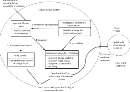
As previously mentioned the proposed model combines UML a We represent the danger source system of MADS model with the collaboration diagram (Figure 3) in order to define and model the scenarios of risk. We present these scenarios in the form of events process as defined in the MADS model. A scenario starts from an initiating event in the collaboration diagram which leads to an ini- tial event.
The danger which flows from this initial event reaches target system causing a final event corresponding to da- mage and consequences.
[image:3.595.126.480.391.697.2]In this paper, we present three examples of risk scena- rios. Two scenarios in the function “to maintain the sa- fety device” and a scenario in the function “to control the In this storage unit, four functionalities are defined:
H. BOULOIZ ET AL. 111
Figure 3. Proposed model founded on the MADS and UML model.
stored products”.
[image:4.595.70.529.404.705.2]4.1. Risk Scenario in the Function “to Control” the Stored Product
Figure 4 shows this scenario which presents the case where operator of storage control did not pay attention to default corresponding to a degradation of storage shelves. The flow of danger associated to this no conforming ac- tion of operator is fall of storage containers which may
lead to physical wounds or also an explosive atmosphere when it about a flammable product.
4.2. Risk Scenarios in the Function “to Maintain Safety Device”
This scenario (Figure 5) presents the case where the pro- cedure of maintenance is not adequate. This irrelevance of the maintenance procedure leads to dysfunction of the safety equipments (i.e. temperature detector of storage). When the temperature of storage (i.e. monomers) ex- ceeds the prescribed temperature, whereas it is not de- tected by the temperature detector, there is a risk of an exothermic reaction of the stored monomers, which can lead to an explosion.
Another scenario may be identified (Figure 6). For example the operator did not respect the procedure of maintenance, which is used to describe the instructions of reliable functioning of safety equipments (i.e. tempe- rature detector of storage). This not conforming action of the operator can generate an inadequate functioning of the safety devices.
The risk scenarios represented with the method which combines MADS model and collaboration diagram allow defining the possible scenarios which generate risk, by
Figure 5. A scenario of risk in a function of maintenance due to use an inadequate procedures of maintenance.
[image:5.595.92.507.410.706.2]H. BOULOIZ ET AL. 113
taking account of initiating events in the interacted com- ponents and in the each function of system.
5. Conclusions
The proposed method aims to integrate the UML model in the MADS model. Danger source system of MADS model is represented with collaboration diagram which make it possible to identify all possible scenarios at each function or use case of the system. It does specify the function of the system on which this scenario is identi- fied, allowing a comprehensive identification of risk sce- narios. This method presents several interests. It repre- sents a mean to support the risk analysis with a systemic method taking into account the interactions between sy- tem components. In addition to risk analysis, this model is a particularly powerful tool that facilitates the under- standing of the organization of an industrial system. This understanding is due to use of collaboration diagram which define the interactions between system compo- nents and these interactions are represented through a chronological representation by sending messages be- tween the components in order to realize a function of the system.
The future work is to develop a computing platform which allows implementing this model.
6. References
[1] C. Cesics, “Introduction to Risk Analysis: Systematic Methods,” Series of Publications of the Committee of Experts for Safety in the Chemical Industry, Notebook No. 4, 1981, pp. 1-8.
[2] C. Ccps, “Guidelines for Hazard Evaluation Procedure with Worked Examples,” 2nd Edition, CCPS AIChE, New York, 1992.
[3] A. Villemeur, “Reliability, Availability, Maintainability and Safety Assessment”, Vol. 1: Methods and Techniques, Vol. 2: Assessment, Hardware, Software and Human Factors, John Wiley, Hoboken, 1992.
[4] M. Monteau and M. Favaro, “Bilan des Méthodes D’Analyse a Priori Des Risques, Partie 2: Principales Méthodes de la Sécurité des Systèmes,” Cahiers des Notes Documentaires INRS, Vol. 139, 1990, pp. 363-389.
[5] F. Craweley, M. Preston and B. Tyler, “Hazop: Guide to Best Practice,” Institution of Chemical Engineers and European Process Safety Centre, Rugby, 1999.
[6] R. L. Rogers, “Methodology for the Risk Assessment of Unit Operations and Equipment for Use in Potentially Explosive Atmospheres,” EU RASE Project n SMT4- CT97, Library Area SAFETYNET, Inburex GmbH Hamm, 2000.
[7] Y. Mortureux, “Preliminary Risk Analysis,” Technical Engineering, Industrial Enterprise, Safety and Risk Man- agement (CD Rom), 2002.
[8] A. Desroches, A. Leroy and F. Vallé, “Risk Manage- ment,” Hermès and Lavoisier, Paris, 2003.
[9] J. Tixier, G. Dusserre, O. Salvi and D. Gaston, “Review of 62 Risk Analysis Methodologies of Industrial Plants,”
Journal of Loss Prevention in the Process Industries, Vol. 15, No. 4, 2002, pp. 2291-303.
[10] F. I. Khan and S. A. Abbasi, “Techniques and Method- ologies for Risk Analysis in Chemical Process Indus- tries,” Journal of Loss Prevention in the Process Indus- tries, Vol. 11, No. 4, 1998, pp. 261-277.
doi:10.1016/S0950-4230(97)00051-X
[11] M. Nicolet-Monnier, “Integrated Regional Risk Assess- ment: The Situation in Switzerland,” International Jour- nal of Environment and Pollution, Vol. 6, No. 4-5, 1996, pp. 441-461.
[12] V. L. Bertalanffy, “General System Theory,” Dunod, Paris, 1993, p. 53.
[13] J. G. March and A. Herbert, “Organizations,” 2nd Edition, Blackwell Business, Cambridge, 1993.
[14] S. Sheard, “Definition of the Sciences of Complex Sys- tems,” Insight INCOSE, Vol. 9, 2006, pp. 25-26.
[15] N. A. Leveson, “New Accident Model for Engineering Safer Systems,” Safety Science, Vol. 42, No. 4, 2004, pp. 237-270. doi:10.1016/S0925-7535(03)00047-X
[16] V. L. Bertalanffy, “General Systems Theory, Foundation, Development, Applications,” George Braziller, Inc., New York, USA, 1969.
[17] H. Bouloiz, E. Garbolino and M. Tkiouat, “Contribution of a Systemic Modeling Approach Applied to Support Risk Analysis of a Storage Unit of Chemical Products in Morocco,” Journal of Loss Prevention in the Process In- dustries, Vol. 23, No. 2, 2009, pp. 312-322.
doi:10.1016/j.jlp.2009.12.001
[18] A. Napoli, “Forest Fire Metrology: Methodological and Technological Approach to Support the Experimental Pro- cess in Forest Fire Behaviour Modelling,” In Actes du Symposium International DELFI Feux de Forêts: Besoins et Innovations, Athènes, 1999, pp. 216-223.
[19] G. Booch, J. Rumbaugh and I. Jacobson, “The Unified Software Development Process,” Adisson-Wesley, New York, 2000.
[20] Object Management Group, UML 2.1 Superstructure Spe- cification, Document: ptc/06-04-02, 2006.
[21] UML Notation guide, OMG, 2006. http://cgi.omg.org/uml/
[22] H. A. Gabbar, K. Suzuki and Y. Shimada, “Design of plant Safety Model in Plant Enterprise Engineering En- vironment,” Journal of Reliability Engineering and Sys- tem Safety, Vol. 73, No. 1, 2001, pp. 35-47.
doi:10.1016/S0951-8320(01)00029-1
[23] J. L. Boulanger, P. Bon and G. Mariano, “Semi Formal Modeling and Formal Specification: UML & B in Simple Railway Application,” International Conference on Soft- ware and Systems Engineering and their Applications, Toulouse, 12-14 October 2004.
namic Risk Management Unveil Productivity Improve-ments,” Journal of Loss Prevention in the Process Indus-tries, Vol. 22, No. 1, 2008, pp. 25-34.
doi:10.1016/j.jlp.2008.07.011
[25] A. Refsdal and K. Stolen, “Extending UML Sequence