SPECIFICATIONS: MODEL DERIVATION, VERIFICATION AND
COMPARISON
Juan Jose Mendoza Santana
A Thesis Submitted for the Degree of PhD
at the
University of St Andrews
2019
Full metadata for this thesis is available in
St Andrews Research Repository
at:
http://research-repository.st-andrews.ac.uk/
Please use this identifier to cite or link to this thesis:
http://hdl.handle.net/10023/17859
This item is protected by original copyright
This item is licensed under a
Creative Commons License
A seamless framework for formal reasoning on
specifications: model derivation, verification and
comparison
Juan Jose Mendoza Santana
This thesis is submitted in partial fulfilment for the degree of
Doctor of Philosophy (PhD)
at the University of St Andrews
I, Juan Jose Mendoza Santana, do hereby certify that this thesis, submitted for the degree of PhD, which is approximately 37,000 words in length, has been written by me, and that it is the record of work carried out by me, or principally by myself in collaboration with others as acknowledged, and that it has not been submitted in any previous application for any degree.
I was admitted as a research student at the University of St Andrews in January 2015.
I received funding from an organisation or institution and have acknowledged the funder(s) in the full text of my thesis.
Date Signature of candidate
Supervisor's declaration
I hereby certify that the candidate has fulfilled the conditions of the Resolution and
Regulations appropriate for the degree of PhD in the University of St Andrews and that the candidate is qualified to submit this thesis in application for that degree.
Date Signature of supervisor
Permission for publication
In submitting this thesis to the University of St Andrews we understand that we are giving permission for it to be made available for use in accordance with the regulations of the University Library for the time being in force, subject to any copyright vested in the work not being affected thereby. We also understand, unless exempt by an award of an embargo as requested below, that the title and the abstract will be published, and that a copy of the work may be made and supplied to any bona fide library or research worker, that this thesis will be electronically accessible for personal or research use and that the library has the right to migrate this thesis into new electronic forms as required to ensure continued access to the thesis.
I, Juan Jose Mendoza Santana, confirm that my thesis does not contain any third-party material that requires copyright clearance.
The following is an agreed request by candidate and supervisor regarding the publication of this thesis:
No embargo on print copy.
Electronic copy
No embargo on electronic copy.
Date Signature of candidate
Date Signature of supervisor
Candidate's declaration
I, Juan Jose Mendoza Santana, hereby certify that no requirements to deposit original research data or digital outputs apply to this thesis and that, where appropriate, secondary data used have been referenced in the full text of my thesis.
i
Abstract
While formal methods have been demonstrated to be favourable to the construction of reliable systems, they also present us with several limitations. Most of the efforts regarding formal reasoning are concerned with model correctness for critical systems, while other properties, including model validity, have seen little development, especially in the context of non-critical systems. We set to advance model validation by relating a software model with the corresponding requirements it is intended to capture. This requires us to express both requirements and models in a common formal language, which in turn will enable not only model validation, but also model generation and comparison.
We present a novel framework (TOMM) that integrates the formalization of class diagrams and requirements, along with a set of formal theories to validate, infer, and compare class models. We introduce SpeCNL, a controlled domain independent subset of English sentences, and a document structure named ConSpec. The combination of both allows us to express and formalize functional requirements related to class models.
Our formal framework is accompanied by a proof-of-concept tool that integrates language and image processing libraries, as well as formal methods, to aid the usage and evaluation of our theories. In addition, we provide an implementation that performs partial extraction of relevant information from the graphical representations of class diagrams.
Acknowledgements
This work would not exist if not for the encouragement of Dr Juliana Bowles, who not only motivated me to pursue a PhD but is also the most supportive supervisor anyone can hope for.
Without any doubt, my parents deserve a fair share of gratitude, for thirty years have they been guiding me to become the best person I can be. I thank them for their wisdom and their tireless effort to give me and my sister the best education possible, and for teaching us to always fight for our dreams no matter what they are.
I must also thank my extended family, including all my aunts and uncles, that took care of me during my childhood, and inspired me to go further. Also, to my cousins that are also my brothers and sisters and with whom I have enjoyed so many amazing moments in life. I am thankful because being as close as we are, I know it would have been difficult to deal with my absence during the PhD years.
And last but not least, I want to thank my soulmate Vinodh Rajan S., who has walked this road with me almost from day one, with whom I have overcome the most unimaginable circumstances. Thanks for being my partner in crime, my other half and my beloved boyfriend.
Funding
Contents
1 Introduction 1
1.1 Motivation . . . 1
1.2 Research Questions . . . 2
1.3 Objectives . . . 3
1.4 Contributions . . . 4
1.5 Evaluation and Results . . . 5
1.6 Content of the thesis . . . 6
2 Overview 7 2.1 Requirements Specifications . . . 8
2.1.1 SpeCNL . . . 9
2.1.2 ConSpec . . . 9
2.2 TOMM . . . 9
2.2.1 Formalization . . . 10
2.2.2 Model Validation . . . 10
2.2.3 Model Generation . . . 11
2.2.4 Model Comparison . . . 11
2.3 T4TOMM . . . 12
2.4 Summary . . . 14
3 Context 15 3.1 Background . . . 15
3.1.1 Software Applications . . . 15
3.1.2 Critical Systems . . . 17
3.1.3 Non-Critical Systems . . . 18
3.1.4 Software Engineering . . . 18
3.1.4.1 Software Development Processes . . . 18
3.1.4.2 Object-Oriented Programming . . . 19
3.1.4.3 Software Testing . . . 20
3.1.4.4 Software Validation . . . 20
3.1.4.5 Software Verification . . . 21
3.1.5 Requirements Engineering . . . 21
3.1.5.1 Types of Requirements . . . 22
3.1.5.2 Requirements Communication Cycle . . . 23
3.1.5.3 Requirements Elicitation . . . 24
3.1.5.4 Requirements Validation . . . 25
3.1.6 Software Modelling . . . 26
3.1.6.1 UML . . . 26
3.1.6.2 Class Diagrams . . . 27
3.1.6.3 OCL . . . 29
3.1.6.4 Model-Driven Development . . . 29
3.1.7 Formal Methods . . . 29
3.1.7.1 Formal Specifications . . . 29
3.1.7.2 Logics . . . 31
3.1.7.3 Model Verification . . . 35
3.1.7.4 SAT/SMT Solvers . . . 35
3.1.8 Data Augmentation for Machine Learning . . . 36
3.1.8.1 Machine Learning . . . 36
3.1.8.2 Neural Networks . . . 36
3.1.8.3 Data Augmentation . . . 37
3.2 Related Work . . . 38
3.2.1 Requirements Specification Document . . . 38
3.2.2 Formal Specification Languages . . . 38
3.2.3 Controlled Natural Languages . . . 39
3.2.3.1 SBVR . . . 39
3.2.3.2 ACE and FE . . . 40
3.2.4 Model Checking . . . 40
3.2.5 Model Validation . . . 42
3.2.6 Model Generation . . . 42
3.2.7 Model Comparison . . . 43
3.2.8 Model Extraction . . . 43
3.3 Previous Work by the authors . . . 44
3.3.1 Construct by Contract . . . 44
3.3.2 TOTOTL . . . 44
3.4 Summary . . . 45
4 Requirements Specification 47 4.1 SpeCNL . . . 48
4.1.1 Parts of Speech . . . 49
4.1.2 Concepts . . . 50
4.1.3 Sentences . . . 51
4.2 ConSpec . . . 53
CONTENTS v
4.3 Requirements Refinement . . . 57
4.3.1 Activity identification . . . 57
4.3.2 Activity specification . . . 58
4.3.3 Clause Construction . . . 59
4.4 Summary . . . 61
5 TOMM: a framework for formal reasoning 63 5.1 Formalization . . . 63
5.1.1 Requirements Formalization . . . 63
5.1.1.1 Elements . . . 64
5.1.1.2 Example . . . 65
5.1.2 Class Diagram Formalization . . . 66
5.1.2.1 Elements . . . 67
5.1.2.2 Example . . . 71
5.2 Class Model Inference . . . 74
5.2.1 Inference Calculus . . . 75
5.2.2 Reliability . . . 77
5.2.3 Example . . . 79
5.3 Class Model Validation . . . 80
5.3.1 Validation Calculus . . . 80
5.3.2 Reliability . . . 85
5.3.3 Example . . . 86
5.4 Class Model Equivalence . . . 87
5.4.1 Equivalence Calculus . . . 88
5.4.2 Reliability . . . 91
5.4.3 Example . . . 91
5.5 Summary . . . 91
6 T4TOMM: a proof-of-concept for TOMM 93 6.1 Resources . . . 94
6.1.1 Natural Language Processing . . . 94
6.1.2 Satisfiability Modulo Theories . . . 96
6.1.2.1 SMT-LIB . . . 96
6.1.2.2 CVC4 . . . 96
6.1.3 Image processing . . . 97
6.2 Meta-Models . . . 98
6.2.1 Specification . . . 98
6.2.1.1 Datatypes . . . 98
6.2.1.2 Automatic Formalization . . . 99
6.2.2 Class Diagram . . . 104
6.2.2.2 Automatic Formalization . . . 105
6.3 Inference . . . 106
6.4 Validation . . . 109
6.5 Equivalence . . . 113
6.6 Class Model Extraction . . . 114
6.6.1 Image Segmentation . . . 114
6.6.2 Information Extraction . . . 117
6.7 Summary . . . 117
7 Evaluation 121 7.1 ConSpec and SpeCNL . . . 122
7.1.1 Evaluation Methodology . . . 122
7.1.2 Evaluation Cases . . . 123
7.1.2.1 Ships Description . . . 123
7.1.2.2 Trains Description . . . 126
7.1.2.3 ATM Simulation . . . 128
7.1.2.4 ACME Library . . . 130
7.1.2.5 Simplified Library . . . 131
7.1.2.6 Steam Boiler . . . 132
7.1.2.7 Laws of Chess . . . 132
7.1.2.8 Whois Protocol . . . 133
7.1.2.9 Light Control System . . . 135
7.1.3 Summary of Evaluation for ConSpec and SpecCNL . . 136
7.1.3.1 Areas of improvement for SpeCNL . . . 136
7.1.3.2 Areas of improvement for ConSpec . . . 136
7.1.3.3 Conclusion . . . 137
7.2 TOMM and T4TOMM . . . 137
7.2.1 Evaluation Methodology . . . 138
7.2.2 Evaluation of Model Generation . . . 138
7.2.2.1 Inferring model manually . . . 139
7.2.2.2 Inferring model with T4TOMM . . . 141
7.2.3 Evaluation of Model Validation . . . 146
7.2.3.1 Manual validation . . . 146
7.2.3.2 Checking invalid model using T4TOMM . . . 148
7.2.3.3 Checking sound model using T4TOMM . . . 151
7.2.3.4 Checking complete model using T4TOMM . . 154
7.2.3.5 Checking valid model using T4TOMM . . . . 156
7.2.4 Evaluation of Model Comparison . . . 159
CONTENTS vii
7.2.4.3 Comparing models with left equivalence using
T4TOMM . . . 161
7.2.4.4 Comparing models with right equivalence us-ing T4TOMM . . . 161
7.2.4.5 Comparing equivalent models using T4TOMM 162 7.2.5 Class Model Extractions with T4TOMM . . . 162
7.2.5.1 Extraction of complete diagram generated by us163 7.2.5.2 Extraction of complete existing diagram . . . 165
7.2.5.3 Results . . . 168
7.2.6 Summary of Evaluation for TOMM and T4TOMM . . 169
7.2.6.1 Threats to validity . . . 170
7.3 Summary . . . 171
8 Conclusions 173 8.1 Threats to Validity . . . 174
8.2 Future Work . . . 175
8.3 Final Remarks . . . 177
Appendices 179 Appendix A Library Example 181 A.1 Requirements . . . 181
A.2 Contract Specification Document . . . 181
Appendix B SMT-LIB models 185 B.1 Inference example . . . 185
B.2 Soundness Model . . . 190
B.3 Completeness Model . . . 191
B.4 Equivalence rules . . . 193
Appendix C Evaluation 199 C.1 Model Inference . . . 199
C.2 Model Validation . . . 204
C.2.0.1 Invalid class model . . . 204
C.2.0.2 Sound class model . . . 213
C.2.0.3 Complete class model . . . 222
C.3 Model Comparison . . . 231
C.3.0.1 Not equivalent class models . . . 231
C.3.0.2 Left equivalent class models . . . 237
C.3.0.3 Right equivalent class models . . . 243
C.4 Class Diagrams for Model Extraction . . . 255 C.4.1 Diagram generated by us containing only attributes . . 255 C.4.2 Diagram generated by us containing only operations . . 256 C.4.3 Coloured Diagram generated by us . . . 257 C.4.4 Existing diagram containing only attributes . . . 258 C.4.5 Existing diagram containing only classes . . . 261 C.4.6 Existing complete diagram containing attributes, and
operations . . . 262 C.4.7 Existing complex diagram . . . 264 C.4.8 Existing diagram drawn by hand . . . 270
List of Figures 273
List of Tables 275
List of Grammars 276
List of Texts 277
List of ConSpec Specifications 278
List of JSON Class Models 279
List of Predicates 281
List of SMTLib models 282
List of Equations 284
List of Acronyms 285
Chapter 1
Introduction
This chapter introduces the motivation for our work, listing the problems we address. They are narrowed down by discussing the research questions the concepts that shape our objectives. Our results are then introduced in the form of individual contributions and their corresponding evaluations. Finally, we provide a description of each chapter as a blueprint for this thesis.
1.1
Motivation
Eight years of personal experience in building industrial software systems has led us to the identification of several problems associated with software models in the development process, particularly, those concerning the maintenance of a consistent relation between requirements and various software models associated with a system. Though software models are to be derived from requirements, in many cases, CASE tools are used to reverse-engineer the models from the existing codebase[48, 70, 164, 169, 181, 224]. This activity does not allow us to establish rigorously whether a given model is valid with respect to the actual requirements of a system, which is a problem we tackle in this research in the form of model validation (which should not be confused with requirements or system validation)[182, 281].
Model validation makes use of formal methods to verify that a given model satisfies a set of self-contained restrictions[24, 72, 74] and is closely related to model checking (which concerns itself only with the internal properties of a model[190]). Current approaches to model validation require the existence of formal specifications, which imposes an additional challenge to software engineers. For this reason, we aim to develop a solution that allows to deal with non-formal specifications, in particular, the specification of functional requirements using elements of natural language.
Model validation is not the only formal activity that has drawn our attention. Model generation is also relevant to us in this context, as it produces the artefacts that will be eventually related to the requirements. Current approaches for model generation can be divided into manual gen-eration, rule-based generation and machine learning generation[2]. Manual approaches[9, 113] are very prone to human error; this is overcome in rule-based approaches[51, 123, 147, 186, 231, 277] by its capabilities to integrate formal methods to generate valid models. This particular aspect of rule-based model generation is the one we develop further in our work.
Machine learning approaches[81, 188, 220, 245, 273, 309] are relatively new, and they depend heavily on the availability of big datasets, which are currently insufficient for model generation from requirements specifications. For this reason, we are concerned about advancing techniques to aid the generation of such datasets.
Even though formal methods have potential applications in industrial software, they have been mostly studied only through their application on life-critical systems[8, 53, 85, 211, 304]; this is partly attributed to the lack of proper competence in software developers to generate mathematical specifica-tions required to use these methods[52, 73, 139, 268]. Having notaspecifica-tions that will allow developers to interface with formal methods intuitively contributes to mitigating this problem.
Apart from that, there is a distinct lack of proper integration of formal methods with the existing developmental tool-chain. Most of the existing tools deal with individual aspects of formal verification, whether it be formalizing requirements[28, 84, 208, 246], checking correctness properties[3, 152, 189], or finding proofs[16, 96, 274]. The lack of seamless integration of these tools represents an additional challenge, which also needs to be addressed.
The current limitations of formal methods in industrial software devel-opment, coupled with their promising applications in model validation and generation (and by extension, model comparison), have been the prime moti-vation that has driven us to perform the research presented in this thesis.
1.2
Research Questions
1.3. OBJECTIVES 3
What are the formal structures and systems required to seamlessly validate, generate and compare UML class diagrams in relation with functional requirements?
To better answer the above underlying research question, we have decom-posed it into the following specific questions.
• What fragments of natural language and formal languages can be combined in order to express and formalize functional requirements?
• What axioms have to be satisfied in order to establish the validity of class diagrams with respect to functional requirements within a formal system?
• What inference rules must be applied to generate valid class diagrams from functional requirements?
• What are the equivalence axioms that enable to compare two class diagrams within a formal system?
• How can functional requirements expressed in natural language, and images representing class diagrams, be automatically processed so that they can be used within systems for formal reasoning?
1.3
Objectives
To summarize our motivation, the overall goal of this research is to elaborate on the foundations of a formal framework that will support different reasoning tasks over requirements and software models. This goal is broken down into the following objectives.
1. Develop a requirements specification format to capture functional re-quirements related to class diagrams.
2. Define a set of formal notations to represent functional requirements and class diagrams seamlessly.
3. Define the formal systems required to achieve class model validation, generation and comparison.
5. Evaluate our specification format against existing sets of requirements.
6. Use our proof-of-concept to evaluate our theories for model validation, generation and comparison within a set of clear cases that cover the different expected outcomes.
1.4
Contributions
Our main contribution is a formal framework enabling seamless validation, generation and comparison of class models. Through the development of our framework, we also make two additional contributions to the specification of functional requirements, and the automation of our framework. These contributions are enumerated below.
• A Controlled Natural Language, named SpeCNL, and a document structure, named ConSpec to capture functional requirements.
• A formal framework named TOMM composed of:
– A set of first-order logic predicates to formalize class diagrams and ConSpec requirements.
– A theory for validation of class diagram with respect to ConSpec requirements using semantic equivalences.
– A theory for generating valid class diagrams from ConSpec require-ments.
– A theory to compare class diagrams based on semantic equivalences.
• A python-based proof-of-concept tool named T4TOMM that supports:
– Partial class model extraction from images of class diagrams using image processing libraries.
– Formalization of class models into SMT-LIB formal models. – Formalization of ConSpec documents into SMT-LIB formal models
using libraries for natural language processing.
– Validation of class models against ConSpec requirements using SMT solvers.
– Generation of class models from ConSpec requirements using SMT solvers.
1.5. EVALUATION AND RESULTS 5
Through this thesis, we continuously use the words integrated and integra-tion to refer to the fact that the formalizaintegra-tion for ConSpec specificaintegra-tions and class models can be similarly (seamlessly) used for either model validation, model generation or model comparison. This concept also denotes the fact that these activities coexist within TOMM and T4TOMM.
As of April 19th, our paper was accepted for the 15th European Conference on Modelling Foundations and Applications (ECMFA). The conference is dedicated to advancing the applications of Model-Based Engineering and will take place from July 15th to July 19th at the city of Eindhoven in the Netherlands. The paper focusses on the formalization of functional requirements, and class model validation. It covers parts 1 and 2 from the list of contributions.
1.5
Evaluation and Results
Our three distinguishable contributions were evaluated in the following manner. To evaluate of requirements specification format, we made use of a subset of requirements taken from a public repository of requirements documents[289], which were translated into our format. From this process, most of the functional requirements related to class models were successfully translated. Some limitations for our specification format were identified when trying to express complex comparison sentences, such as “the temperature must be between 10°C and 15°C” . Besides, we observed some limitation when specifying a sequence of actions, which though nor required for class diagrams, might be useful for sequence diagrams and other models. Further discussion is provided in Section 7.1.
Our formal framework was evaluated through various scenarios containing valid and invalid class models, which were checked against a set of functional requirements. We then checked class models generated from requirements against existing valid models for the same requirements. Model comparison, in turn, was evaluated in terms of existing and generated models that cover the scenarios of equivalence and difference. Our proof-of-concept, described in Chapter 6, showed that the theories we developed satisfy the expected results for validating, generating and comparing classes, attributes, operations, and inheritances. The evaluation of our formal framework and our proof-of-concept is discussed in Section 7.2
however, require further manual corrections to be usable. This evaluation is expanded in Section 7.2.5.
Possible extensions for our work were identified through Chapter 7 and summarised in Section 8.2.
1.6
Content of the thesis
The following chapters will elaborate on how we addressed our formulated problem, objectives and research questions.
Chapter 2 starts by presenting an overall picture of this work, and how our contributions are established through a formal reasoning framework and a proof-of-concept. This chapter describes a roadmap for the thesis, which helps the reader to target specific topics if desired.
In Chapter 3 the context for our research is established. Section 3.1 introduces the basic concepts required to understand our contributions. In Section 3.2 we discuss the state-of-the-art related work. Additionally, in Section 3.3 we present previous work done by us, which though different from the current research, provided us with experience and motivation to develop this work.
Chapter 4 defines all the elements that integrate our controlled language to specify functional requirements, as well as our structure for contract-based specifications. In this chapter, we demonstrate how typical requirements are translated into our specification format.
Chapter 5describes our formal reasoning framework, which supports the formalisation of class models and specifications, model inference, validation and comparison. This chapter presents the axioms, inference rules and semantics required for each task.
InChapter 6, we discuss the implementation of a proof-of-concept (tool) to support our framework. We describe how class diagrams and requirements specifications are automatically formalised and checked by a formal solver in order to enable automated reasoning. The external dependencies for natural language processing, model verification and image processing are also described here.
Chapter 7 describes the evaluation process for our specification format, our reasoning framework, and our proof-of-concept. The different method-ologies to evaluate each of our contributions are described in this chapter, together with the different resources and cases to conduct the evaluation.
Chapter 2
Overview
The overview provided in this chapter will help the reader to understand the structure of this dissertation, and relate each chapter to its corresponding component in our proposed framework. Several concepts and terms are mentioned here; however, they are properly explained until Chapter 3.
The framework described here addresses existing problems regarding software models, namely model validation, model verification and model comparison. The approach we propose to tackle these problems makes use of formal methods to establish a relationship between the elements of functional requirements and class models. Though formal methods are more commonly used in critical systems[53, 85, 130, 149], our framework allows us to demonstrate their usage in the development of non-critical systems defined in Section 3.1.3.
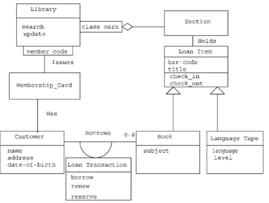
Throughout this thesis, we use as a reference the library system initially described by Callan[62], and then expanded by other authors[42, 128, 142]. The original requirements for this system are shown in Text 2.1, while the original class diagram is shown in Figure 2.1. These requirements and diagram are used to exemplify the application of our specification formats (Chapter 4), the theories that compose our theoretical framework (Chapter 5), the proof-of-concept developed (Chapter 6) and the evaluation of our contributions (Chapter 7).
Figure 2.1: Class Diagrams for Library Example
A library issues loan items to customers. Each customer is known as a member and is issued a membership card that shows a unique member number. Along with the membership number, other details on a customer must be kept such as a name, address, and date of birth. The library is made up of a number of subject sections. Each section is denoted by a classification mark. A loan item is uniquely identified by a bar code. There are two types of loan items, language tapes, and books. A language tape has a title language (e.g. French), and level (e.g. beginner). A book has a title, and author(s). A customer may borrow up to a maximum of 8 items. An item can be borrowed, reserved or renewed to extend a current loan. When an item is issued, the customer’s membership number is scanned via a bar code reader or entered manually. If the membership is still valid and the number of items on loan less than 8, the book bar code is read, either via the bar code reader or entered manually. If the item can be issued (e.g. not reserved) the item is stamped and then issued. The library must support the facility for an item to be searched and for a daily update of records.
Text 2.1: Original requirements for the Library system described by Callan[62]
2.1
Requirements Specifications
2.2. TOMM 9
do no satisfy the constraints that we have set for our framework, hence the need for a new document structure, and a new language to express functional requirements in a way that can be formally related to class diagrams. Both language and document structure are briefly introduced in here, while their details are explained in Chapter 4.
2.1.1
SpeCNL
The language used on a daily basis to communicate with our peers is powerful enough to express emotions, timed events, and an endless number of complex constructs. However, some of these aspects of the language are not relevant when specifying software requirements. SpeCNL is a language based on the grammatical elements of a simplified form of English, to express sentences related to class diagrams. The description of these elements is the purpose of Section 4.1.
2.1.2
ConSpec
SpeCNL allows writing simplified sentences with well-defined structures. How-ever, these sentences alone do not constitute a requirements document. We then propose a document structure, named ConSpec, to delimit the semantics of these sentences in the context of functional requirements. ConSpec is properly described in Section 4.2.
2.2
TOMM
Thinking Of Models and More, or TOMM for shorter, is the name given to our framework. The word thinking denotes our research activity but also refers to the formal reasoning capabilities that distinguish TOMM, and which are explained in Chapter 5.
TOMM was initially designed to support model validation as a comple-ment for model checking. However, through its developcomple-ment, we observed the opportunity to extend it over other ways of formal reasoning, such as model generation through inference, and model comparison thorough axiom checking. These extensions are part of the current version of TOMM and also demonstrate its flexibility.
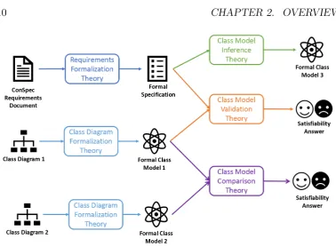
Figure 2.2: Schematic diagram for TOMM
Sections 2.2.1 to 2.2.4 contain an introduction of the theories underlying TOMM, and their detailed description is found in Chapter 5.
2.2.1
Formalization
It is seen in Figure 2.2 that formalization theories precede the usage of the other theories. This step is required to capture both functional requirements and class diagrams in one common language that will enable formal reasoning. In Section 5.1, we discuss how to formalize these artefacts using predicate-logic, which will be introduced in Section 5.1.
2.2.2
Model Validation
In principle, anyone can draw a class diagram, but not every drawn class diagram is guaranteed to be valid with respect to the requirements it is supposed to capture. In the context of TOMM, a diagram is valid if all of its elements are related to some elements in the specification, and if all the elements of the specification are mapped to some elements in the diagram. We define the notions of soundness and completeness in Section 5.3 in order to capture formally capture these conditions.
2.2. TOMM 11
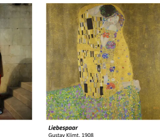
Figure 2.3: The kiss
outdated class diagrams, which is a common problem in software development. It also helps to automate the evaluation process of collections of diagrams, which is a common task when teaching software engineering.
2.2.3
Model Generation
Drawing class diagrams is less about aesthetics than it is about analysis and abstraction; these are intended to encode information about a problem and its corresponding solution. Identifying the elements of a problem and capturing them in a class model is what we do through inference, which is discussed in Section 5.2. This approach to model generation guarantees that inferred models are valid concerning our validation theory.
2.2.4
Model Comparison
By observing the work that Hayez and Klimt have gifted us (Figure 2.3), it becomes evident that it is possible to have more than one representation of one single concept, in this case, a kiss.
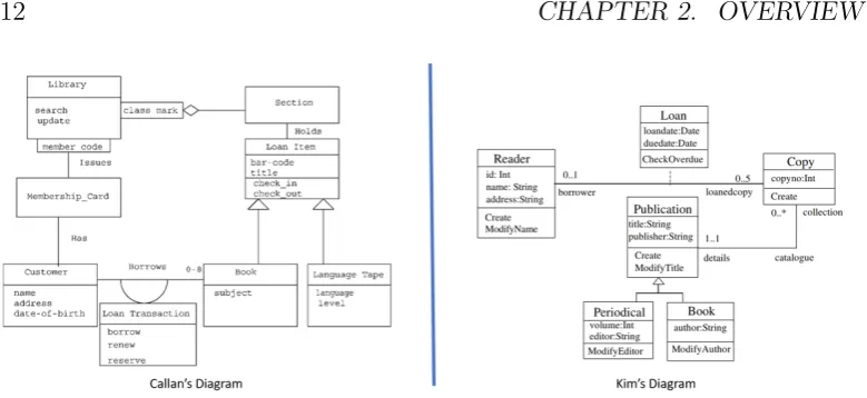
Figure 2.4: Two diagrams representing the same requirements for a library system
In the case of the paintings, it is evident for the observer that though they are not exactly the same, they capture the same concept. However, a more in-depth analysis of their elements must be conducted in order to determine the similarities between two class diagrams. A formal theory to determine model equivalence is the work we present in Section 6.5.
If two or more diagrams are proved to be equivalent, then they can be alternatively used to represent the same requirements, which is desirable when generating diagrams using machine learning techniques (see Section 3.1.8 for further detail).
2.3
T4TOMM
TOMM is a theoretical framework to reason about class diagrams formally. However, the impact of any theory is better measured through practice. Hence the need to develop T4TOMM, which is a proof-of-concept that supports the theories described in Chapter 5, and also deals with the specifications defined in Chapter 4. All of the technical aspects of T4TOMM, including libraries, algorithms and meta-models are detailed in Chapter 6.
2.3. T4TOMM 13
Figure
2.5:
Sc
hematics
for
2.4
Summary
In this chapter, we presented an overview of our framework. We introduced how specifications and models interact with each other to achieve inference, validation and comparison. In addition to the core elements of our framework, we introduced the structure proposed to specify requirements, and a proof-of-concept that integrates this structure with our theories to create a complete workflow.
Chapter 3
Context
The groundwork forsoftware specifications and models is discussed throughout this chapter. Initially, we lay out the relevance of software as a subject of study by summarizing its applications. Subsequently, software engineering and requirements engineering are introduced as the disciplines to which contributions are made through this thesis. We also elaborate upon the fundamental concepts used in requirements specifications, software modelling and program verification.
In this chapter, we also present the state-of-the-art of the most relevant related work, which includes a discussion about existing specification languages and documents, and formal systems for model verification and comparison. We finally present the work we have done previously, which has also motivated the current research.
3.1
Background
In this section, we list the different concepts from software engineering and computer science that build the context for our work. This purpose of this section is not to exhaustively cover each concept, but to introduce the most general ideas and to provide the appropriate references should the reader require more information.
3.1.1
Software Applications
Our research is better appreciated by reflecting upon the evolution of software applications and their impact on modern society.
During the early 50s, software was mainly used by the scientific community to perform complex mathematical calculations[110]. Later, in 1966, the launch
of the DOS/360 operating system by IBM marked the beginning of an era for multi-purpose programs that could be executed from a command line in a straight-forward manner. The next big leap occurred during the 70s, with the popularization of Graphical User Interfaces (GUIs)[230, 259]. From interactive components to resource management, Operating Systems have played a fundamental role in the steady growth of the application of software.
However, Operating Systems did not uniquely contribute to the expansion of software usage. The Internet has, in recent years, also contributed sub-stantially. In 1970, the ARPANET project was launched as the first global network of interconnected computers. The development of communication protocols was needed for it to work. Consequently, first applications, such as the case of the electronic mail and bulletin boards, were developed in the 1970s. The World Wide Web in the 80s and the first web browser in the 90s ushered a new direction with the emergence of web applications. Towards the beginning of the 2000s, the Web 2.0 introduced a social aspect, and more recently, the Internet of Things has become fundamental for its ubiquitousness.
The development of programming languages has eased the creation of software systems that address well-defined problems within specific domains. For instance, while COBOL[269] was mainly useful to encode communication procedures within banks, Ada was a multi-purpose language developed by the U.S. Department of Defence for military and commercial use[57]. Later examples include languages like C[261], which was preferred to build hardware controllers, and Java[18] which was praised for its cross-platform compatibility. More recently, the survey of programming languages conducted by TIOBE[58] has shown the increasing popularity of Python[263], which has to do with its usage in data science and machine learning[92]. Table 3.1 shows a long term history of the current ten most used programming languages.
Language 2019 2014 2009 2004 1999 1994 1989
Java 1 2 1 1 12 -
-C 2 1 2 2 1 1 1
C++ 3 4 3 3 2 2 3
Python 4 7 5 9 27 21
-Visual Basic .NET 5 10 - - - -
-C# 6 5 6 7 23 -
-JavaScript 7 8 8 8 17 -
-PHP 8 6 4 5 - -
-SQL 9 - - 6 - -
3.1. BACKGROUND 17
To this point, we have illustrated how these technologies have historically opened new horizons for the applications of software. However, our day to day activities themselves provide opportunities for software applications. These new opportunities very often demand existing technologies to be improved and new ones to be created in order to cope with our needs. This is evident when noticing the need to improve fraud detection in banks[12, 116, 239], or tumour recognition in digital imaging[87, 154, 201], or self-driving cars in the automotive industry[122, 250, 275]. These specific needs, in turn, push the development of new processors that deal with data and machine learning algorithms efficiently. This is the symbiotic relationship between technology and software applications that we introduced earlier.
The fact that software is present in almost any aspect of our life, including health, finance, business management, marketing, transport, home and fashion amongst others, makes it not only interesting but also an important subject of study. Thanks to high-level programming languages, software development is becoming more accessible, resulting in a large number of people developing applications. However, the increase in accessibility comes with its own set of risks and concerns. Because not every developer takes appropriate care[105, 175] of a software’s safety, security, quality, correctness, testing, usability, and maintainability, amongst other aspects, and in fact, this is not a trivial task[117, 133, 192, 227]. For this reason, it is necessary to construct frameworks like TOMM, that support developers in the achievement of such tasks.
3.1.2
Critical Systems
3.1.3
Non-Critical Systems
We consider non-critical systems all those that do not imply a risk on human lives. In particular, we look at systems used on daily activities, such as mobile applications and web applications. These systems are commonly integrated by several components, namely user interfaces, communication protocols, web services, etc., and their development process prioritizes functionality and time to market over safety checks and advance verification. As part of this work, we investigated the application of techniques used in the development of critical systems into non-critical ones.
3.1.4
Software Engineering
Over time, processes followed to construct software have evolved together with its applications. In 1965, Dijkstra stated that “programming is the art of organising complexity, of mastering multitude and avoiding its bastard chaos as effectively as possible”[102, p. 6]. His work, amongst others [101, 151, 301], was essential for the development of Software Engineering as a discipline; which has its origins in the 1968 NATO conference on the same subject [204, 232]. Since then, SE has been driving the constant and rapid development of new tools and methodologies that support the construction of software systems.
3.1.4.1 Software Development Processes
Software Engineering pays particular attention to the study of models that describe the process to build software applications. These models are better known as software development life cycles (SDLC), and define the activities to be performed, the artefacts to be generated at every stage, and the different roles to be played by all the people involved in the process, such as users, managers, sponsors, developers, testers, and all the stakeholders in general.
Sequential life cycles, such as the Waterfall[39, 40] model depicted, whose sequence of stages are shown in Figure 3.1, and the V-Model[120], define steps to be executed consecutively until the software system is completed. The stages of the waterfall model are usually used as a reference for other life cycles. Differences are present in the names of the stages, their scope, the way they are approached and the interaction amongst them. However, from a conceptual point of view, these key stages are present in any software development process.
3.1. BACKGROUND 19
Figure 3.1: Waterfall Model
process[191]. Their inflexibility has motivated the development of incremental life cycles, such as Spiral and Prototyping[266]. These processes incorporate a faster build-fix-release iteration, in which small features are incrementally added to a software product, instead of expecting one “complete” system.
The evolution of applications described in Section 3.1.1 has triggered an exponential demand for software products; together with the need for more realistic and suitable development processes. Furthermore, theManifesto for Agile Software Development[14] has set the grounds for a new generation of life cycle models: the agile methods[5, 6]. These methods are characterised for putting interaction between stakeholders in the centre of the process as a critical factor to efficiently develop functional and flexible software applications.
Understanding precisely how a software system is going to participate in the solution of a problem is always the first stage of any life cycle, whether it is agile or waterfall based. Poor understanding of the expected use of a system implies that errors are carried into every stage of the development process, resulting in a defective product. How to adequately define the features required from a software application is the subject of study of Requirements Engineering; which will be discussed in Section 3.1.5.
3.1.4.2 Object-Oriented Programming
a system that is both comprehensive and comprehensible. It also improves the maintainability of the system. Therefore, it is no surprise that OOP has a dominant presence in all facets of programming, particularly concerning Software Engineering.
OOP had its origins with the Simula programming language in the 1960s. However, the concept was popularized by Smalltalk in the ’70s and ’80s. While there is not a general consensus what exactly constitutes OOP, a language can be considered to support it if it supports the following concepts: Abstraction,
Class, Encapsulation, Inheritance and Object in terms of structuring the language and Message Passing, Methods and Polymorphism in terms of behaviour. Expanding on these individual concepts is beyond the scope of this research. A good overview of the history and on what constitutes OOP is presented in the work of Armstrong[17] and Kim[228, 234].
3.1.4.3 Software Testing
Software testing[15, 56, 228, 229] is performed across the development process to check for the presence or absence of errors in the programs being developed. Software testing is done by comparing the expected outputs from an ideal system, with the actual output produced by the real system. In this way, several problems are detected, including syntax errors, unexpected behaviours, and missing functionality.
Software testing techniques approaches are broadly divided into black-box testing and white-black-box testing. While black-black-box testing aims to check the program’s functionality in relation to its specification, white-box testing checks the structure of the program in relation to its underlying code.
Software testing is closely related to software validation and verification, which are discussed in Section 3.1.4.4 and Section 3.1.4.5 respectively.
3.1.4.4 Software Validation
Software validation aims to check if the system being developed is the one expected by the user[281, 286]. Software testing (Section 3.1.4.3) and re-quirements validation(Section 3.1.5.4)[182, 200, 244] are some of the most common methods to conduct software validation[255, 281, 286]. Other meth-ods are partial inspections and reviews through every stage of the development process[281].
3.1. BACKGROUND 21
3.1.4.5 Software Verification
Software verification aims to check if the system being developed complies with its specifications[10, 281, 286]. Techniques for software verification are usually classified into static and dynamic.
3.1.4.5.1 Static Verification
Static verification, also referred to as static analysis, checks the code of a program without executing the program itself[89]. Compilers typically perform static analysis for programming languages, which detect syntactic mistakes in the code.
In addition programs can be checked against formal specifications through programs for formal verification (discussed in Section 3.1.7.3). These speci-fications are captured in formal languages, such as Spec#[32] for C# code, JML[193] for Java code, and Eiffel contracts for the Eiffel programming lan-guage[218]. Formal specifications are further discussed in Section 3.1.7.1. This combination of formal specifications and program code are key to perform static verification.
3.1.4.5.2 Dynamic Verification
Unlike static verification, dynamic verification does require the execution of the program being verified. This is typically done through testing and experimentation. Because testing frameworks do not commonly rely on formal specifications, it is necessary to design suitable test cases that capture the requirements for the system being verified.
Dynamic verification is limited by the samples used in the sequence of experiments and tests, and it is rarely possible to conduct exhaustive testing for absolutely all possible scenarios. For example, it is not possible to exhaustively test a program to add two natural numbers, for it requires an infinite number of test cases. This problem is better addressed through static verification, in which formal theories for natural numbers are used. Though dynamic verification is more practical, it lacks the rigour achieved through static program verification[10].
3.1.5
Requirements Engineering
engineering has been made clear in Section 3.1.4, we need to focus now on the role of Requirements Engineering. We examine the purpose of requirements engineering and its role in the successful construction of software applications.
The term requirements engineering has been around since 1979 [13]; but it was not until the 90s that it became a specific research area, thanks to the IEEE Computer Society [288]. The CHAOS Report [157] published by the Standish Group International in 1994 had a significant impact on the way system requirements are perceived. Ever since, requirements engineering has received increasing attention from the practitioners of software engineering.
The CHAOS report states that 13% of the IT executives surveyed at-tributed the success of a software project to theclear statement of requirements, which makes it the third most important factor. The report mentions realistic expectations, and clear vision & objectives as success factors with 8.2% and 2.9% respectively.
In contrast, the report shows factors that challenge projects, such as
incomplete requirements & specifications, changing requirements and specifica-tions”, andunrealistic expectations with 12.3%, 11.8%, and 5.9% each one of
them.
Even though the validity of this report is arguably outdated [131], it has motivated a considerable amount of research in the area of requirements engineering, and it makes it clear that requirements-related factors have a high impact in the success, challenge or failure of a software project.
While software engineering studies how a system should be constructed to solve a specific problem, requirements engineering studies how to state that problem. The interaction of these two disciplines makes it possible to propose methodologies that support a more precise definition of what a software should do and how it should do it.
In Sections 3.1.5.1 to 3.1.5.4, we introduce the most significant work in requirements engineering that sets the grounds for our contribution to this discipline, before we detail them in Chapter 4.
3.1.5.1 Types of Requirements
Expectations for a software application are divided into two: those that are related to the problem addressed, and those that have to do with the qualitative attributes of the product itself. In the literature, these expectations are referred to as functional and non-functional[281] requirements respectively.
Functional requirements describe explicitly what the system should do, i.e. what business rules must be followed to solve the problem. Examples of these rules are: the system has to record the name and age of the users, and
3.1. BACKGROUND 23
Figure 3.2: An example of a Requirements Communication Cycle
Non-functional requirements express characteristics of the system as a whole; that is, the capabilities and emergent properties it should observe. Examples of these properties are reliability, response time, memory usage, etc.
While non-functional requirements are well characterised[182] and are standard for any software system, functional requirements are rather specific to the domain of the system and to the problem it aims to solve. These qualities justify the need for further research targeting functional requirements, which is the case of our work.
3.1.5.2 Requirements Communication Cycle
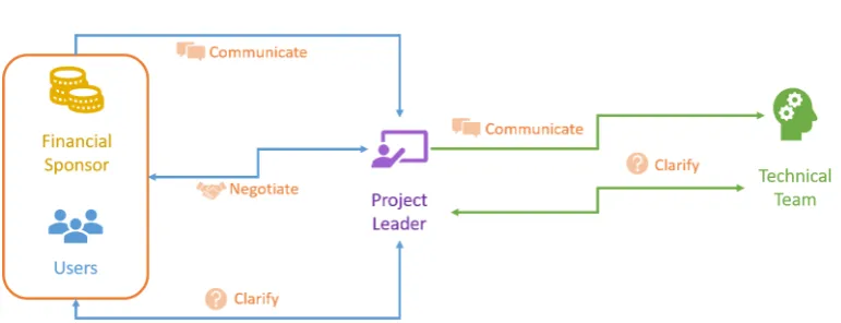
Together with the elicitation techniques, it is necessary to establish an ap-propriate communication process amongst the stakeholders. We refer to this process as the requirements communication cycle, and its implementation may have subtle variations depending on the development methodology[248] being used and the roles defined in it. Nonetheless, it is possible to identify the most general elements of any communication cycle, as it is depicted in Figure 3.2.
In this example, the financial sponsor and the system users communicate the expected functionality to the project leader. This role is typically per-formed by the more senior members of the development team, such as software architects or product engineers, or by members of the administration team, including the product owner, team leaders, project managers, or SCRUM masters1 where applicable. The project leader will review the requirements and will negotiate them with the sponsor and the users, just in case some requirements are not within the resource limits of the project (time, budget,
1The SCRUM master plays the role of the project manager in the SCRUM
knowledge, etc.). The project leader will also communicate the requirements to the technical team, typically formed of developers, testers, and quality assurance certifiers. The technical team can request clarifications from the users and sponsors via the project leader. Through the negotiations and clar-ifications, the requirements will be updated, until the final version is agreed upon. This refined version will be used to generate the software specification that will guide the current iteration of the development process.
3.1.5.3 Requirements Elicitation
Requirements elicitation is a common activity in all software development processes (Section 3.1.4.1). The goal of this activity is to precisely define the expected functionality of a software application in the form of requirements. This is achieved through the understanding of the problem to be addressed, and the discovery of the relevant business rules that will provide the solution. When eliciting requirements, there is a series of tasks that should be performed, such as discovering, understanding, classifying, organising, pri-oritizing, negotiating and documenting requirements[281]. These activities are performed differently according to the experience of the developing team, the structure of the organisation, and the domain of the business. However, there is a series of commonly used techniques that allow us to succeed in the activities mentioned above.
The most utilised technique to collect requirements is interviewing. One way is to listen to stakeholders explaining the business processes in an open way, similar to brainstorming. Another way of doing it is to ask a set of well-defined questions to specific stakeholders. The second alternative is complementary to the first one in order to clarify doubts arising from the open session. Regardless of the format, or combination of formats used for the interviews, it is important to preserve a record of the output of this process, so that the information is available for future references.
Less common techniques[137, 288, 312] are ethnography, stories and sce-narios, introspection, focus groups, repertory grids, card sorting, protocol analysis, etc. We do not discuss these techniques in detail, as we consider them as variations or extensions of interviewing; and their specific details do not have an impact on our work.
From the analysis of the existing techniques[182, 249, 281], and our experience in the software industry, we consider that semi-open interviews combined with observation, constitute the most suitable approach to elicit functional requirements.
3.1. BACKGROUND 25
While their needs are being expressed, the leader must take notes and try to identify possible use-cases[77]. A use-case is, in essence, an atomic, well-defined, activity that occurs under specific circumstances. An example of a use case for a library system would be “The user of the library can borrow books and tapes”.
Once all potential use-cases have been identified, their attributes must be clarified by including all constraints, and actors for each activity. Examples of these components are the constraint on the maximum number of books that can be borrowed, the dependency on a valid membership card, and the actors who do the action, either public in general or members of the library. Further interviewing and direct observation of the task at hand should lead the clarification of its attributes.
In some circumstances, business rules are already expressed through written documents, diagrams, or manuals. Hence, further review of existing resources is required to complement interviewing and observation in order to identify and detail use-cases. In addition to our preference of techniques, other alternatives from the ones mentioned earlier, or from any other personal experience, are applicable in the construction of complete specifications.
3.1.5.4 Requirements Validation
According to Sommerville[281], requirements validation is “the process of checking that requirements define the system that the customer really wants”. Its goal is to identify problems with the requirements document that could have an impact on the development of the system. For instance, incomplete requirements derive into incomplete models, which at the same time produce incomplete software applications. This problem implies that the different artefacts (models, code, test cases, documentation, etc.) produced in every stage of the development process have to be reworked[182, 235, 281].
Different literature about requirements validation agrees on the aspects of requirements that have to be checked, such as consistency, completeness, feasibility, and testability [47, 182, 281]. Techniques proposed to validate requirements include reviews with stakeholders, cross-referencing, readings, prototyping, and use cases[47, 182, 244, 281]. More recent approaches attempt to integrate formal representations, such as ontologies, in the requirements validation process[98, 111, 148].
3.1.6
Software Modelling
Design and modelling is a relevant activity in most software development life cycles, even agile methodologies. The agile manifesto[14] establishes that “Continuous attention to technical excellence and good design enhances agility” and “The best architectures, requirements, and designs emerge from self-organizing teams” . From the Waterfall process depicted in Figure 3.1, it is observed that this activity comes after requirements have been defined and analysed, and before the program is built (or coded).
Modelling systems is the equivalent to drawing the blueprints for a house. That is, to define its components, as well as their shape, their scope and their interaction, based on the requirements and the best practices for software development.
Through this activity, high-quality modular programs are developed, which feature reusability, extensibility, readability amongst its qualities. Modelling also increases awareness on reliability, security and safety properties of a software system.
Models are abstractions that allow us to visualize different perspectives of the software to be built, including structural and behavioural elements. Different modelling techniques exist and are used for different purposes. For instance, mock-ups are preferred when designing front-end software components. One particular modelling approach we are interested in is the one proposed through the Unified Modelling Language (UML), which will be discussed next.
3.1.6.1 UML
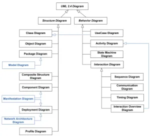
The Unified Modelling Language (UML)[258] is a collection of diagrams proposed by the Object Management Group (OMG) as part of their Model Driven Architecture (MDA). The language has been widely adopted in indus-try and academia as the standard way to document, model and visualize the structure and behaviour of software systems together with the interaction between its components. The Figure 3.3 shows all the diagrams that are part of UML. In Section 3.1.6.2, we will discuss further Class Diagrams, which are the current object of our research.
3.1. BACKGROUND 27
Figure 3.3: UML Diagrams
embraced the modelling language either natively or via extensions.
Despite its virtues, UML also carries some risks[38]. The misuse of the diagrams and the wrong interpretation of their intended purpose is one common problem amongst its users. Besides, there is the risk of the overuse, as the attempt to model every aspect of every system with UML.
While it is clear that UML works seamlessly with Object-Oriented method-ologies and programming languages, it is not the case for applications based on web languages such as HTML and CSS, which are modelled better trough visualizations such as mockups[203, 262].
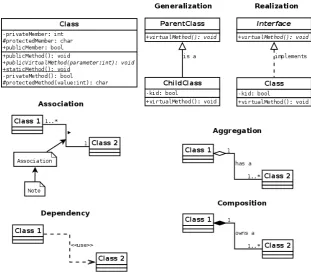
3.1.6.2 Class Diagrams
Figure 3.4: UML Class Diagrams Cheat Sheet
parameters, and the constraints for invocation.
The relations between classes are described through a set of well-defined association types. The most common examples of binary associations are aggregation and composition. The former is used to indicate that a property is part of a composite and that the property exists independently. The later, in contrast, indicates that the parts cease to exist when the composite does. Figure 3.4 summarizes the main elements of a class diagram. A compre-hensive reference for UML class diagrams, and UML in general, is available in the work of Fakhroutdinov[115] as well as the books of Rumbaugh[265], Pender[241] and Fowler[121].
3.1. BACKGROUND 29
3.1.6.3 OCL
The Object Constraint Language (OCL)[258, 278, 296, 297] is another stan-dard of the OMG, which extends UML to specify constraints over classes, their attributes and operations formally. It is a declarative language with precise semantics to build well-formed formulae that express restrictions over the possible values of the elements of an object-oriented model. It is based on first-order predicate logic with a syntax similar to that of object-oriented programming languages.h
Constraints are expressed in the context of UML classes, but they are evaluated for the instances of the class. There are three main types of constraints. Invariants is a condition that must hold during the entire lifetime of an object. Preconditions are constraints that must hold before the execution of a given operation, while postconditions must hold at the end of its execution. These conditions allow us to capture parts of the behaviour of the operation itself within static structural diagrams. In Section 3.1.7.2.3, we discuss these constraints further within the context of Hoare logic and Design by Contract.
3.1.6.4 Model-Driven Development
This approach to software development puts models at the centre of the development process[19, 271, 281]. It has been pushed forwards thanks to the development of Computer-Aided Software Engineering (CASE) tools[215, 270], and the efforts of the OMG to develop modelling standards[258, 279].
3.1.7
Formal Methods
Formal methods are a collection of mathematical languages, theories and techniques to specify, analyse and verify software systems[73]. In this section, we introduce the elements of formal methods that are part of our work.
3.1.7.1 Formal Specifications
The main difference between requirements and specifications is that the former are usually express in an informal, natural and open way through natural language. The later, instead, are meant to be precise, unambiguous, and structured. This is achieved employing special notations, such as diagrams, mathematical equations, formal languages, or domain-specific constructs.
Another noticeable difference is that, while requirements tend to reflect the expectations of a system as a whole, specifications deal with particular elements of the system, such as architecture, functionality, component inter-action, roles, etc.o In this way, requirements are understood as the superset of various specifications.
Throughout this work, we indistinctly use the terms requirements specifi-cation, software specifispecifi-cation, functional specifispecifi-cation, system specification or simply specification, to refer to the structured representation of the functional requirements.
We already mentioned some of the problems that proceed from com-munication in natural language. In order to deal with such problems, we surveyed specifications in the literature. The work of Kontonya[182] proposes
data-flow modelling, semantic data models, object-oriented approaches and
formal methods. In addition, Pressman[249] mentions written documents,
graphical models, formal mathematical models, usage scenarios, and proto-types. Moreover, Sommerville[281] discusses variations of natural language,
graphical notations, and mathematical specifications. The interesting overlap amongst the work of these authors and their relation with our research is further discussed in Chapter 4.
The choice of the format to be used depends on the type of software application to be developed. For instance, if we were to describe a software that affects human lives, formal methods would be a sensible choice, because it allows torigorously guarantee that specific properties hold. In contrast, if we were to define a system mainly composed of visual elements, prototypes
would be more suitable.
3.1. BACKGROUND 31
3.1.7.2 Logics
Logics are formal languages with precise semantics and syntax. The later is defined thorough grammatical rules used to generate all well-formed formulae, within the language. A logic may additionally define an inference engine, which is a set of laws that allow the generation of new well-formed formulae from existing ones. A logic system integrated by a formal language and an inference engine allows to reason about statements within the system[86, 118, 282].
In a logic system, there is an initial set of well-defined formulae, called axioms, that define facts we know or assume to be true. Then, one can try to ask if another given formula is derived from the facts we know. If the application of the laws in the inference engine eventually leads to the formula in question, we have proven that such formula follows from the facts. This is just an overview of the way logic systems[303].
3.1.7.2.1 Popositional Logic
Propositional logic or propositional calculus is the most basic type of logic. In it, simple propositions of the type “ Plato is a man” are expressed. Propositions are usually represented by letters from the alphabet, and they al-ways must have either atrue or false value[303]. In other words, a proposition is an assertion about some fact.
Propositions can be combined to form more complex structures through the following logical connectives: not (¬), and(∧), or(∨), if...then( =⇒ ), and if and only if( ⇐⇒ )2. If we assume that the literal P represents the proposition “ Plato is a man”, and the literal Q represents the proposition “ Plato is mortal”, we can write “ Plato is human and mortal” asP ∧Q, which is a well-formed formula within propositional calculus.
In order to reason about these propositions, a deductive apparatus or inference engine is required. One the apparatuses used with this logic is the
(Gentzen) natural deduction system[129], which defines rules to introduce and eliminate connectives. For example, assuming we have two propositionsAand B, it is possible to combine them in (A∧B); and from A and (A =⇒ B) we can infer B. This rule is usually written as shown below, and it is well-known asmodus ponens or implication elimination[106, 112, 303]. With these rules, propositional logic becomes a powerful method to perform formal reasoning.
A (A =⇒ B)
B
The type of reasoning shown above does not apply to all aspects of human reasoning. For instance, in the expression “I’ll meet you after school”, we need to understand the implications of the word “after”. Sentences like “John’s cat is big” may require an interpretation of the ownership of the cat, and sentences like “this place is nice” depends upon the understanding of which place we are referring to. Despite these limitations, propositional calculus has set the grounds for the development of more extensive logics.
3.1.7.2.2 Predicate Logic
First Order Logic (FOL)or predicate calculus3 is one of the extension of propositional logic. In it, we model the world through the establishment of properties amongst elements. These properties are called predicates, and the elements can be either fixed or variable. For instance, to express the proposition “Plato is a man”, we define the property of being a man as MAN(x), where x is a variable; then we apply that property to the specific subject Plato, resulting in the predicate MAN(P lato).
The ability to deal with properties also requires the ability to deal with subjects to whom the properties apply. In the previous example, we applied the property MAN(x) to one specific subject, but FOL also allows us to reason about groups of subjects. This is achieved through theuniversal quantifier
(∀), which states that a given property holds for all the elements in a given set, and the existential quantifier (exists), that indicates that a property holds for some (at least one) of the elements in a set. An example of quantification is ∀xMAN(x) =⇒ MORTAL(x), which means that for any subjectx, if x is a man, then x is also mortal.
In predicate logic, the connectives of propositional calculus are combined with predicates, variables and quantifiers in order to build more complex expressions. For instance, note that there is no “empty” quantifier, so if we wish to say that a property does not hold for any element, we can use the formulas¬∃xP(x) or∀x¬P(x). Predicates also allow us to express relations between subjects. We can express that Socrates is Plato’ teacher thorough the formula TEACHER(Socrates, P lato).
We can also build more complex sentences such as “Mary has a lit-tle lamb”, translated into the expression ∃x ∈ P eople,∃y ∈ Animals | IS NAMED(x, M ary)∧IS LAMB(y)∧IS LITTLE(y)∧HAS A(x, y). This last example illustrates the complexity required to express short sentences in FOL, and thus the reason why this format is not recommended to write requirements specifications.
3.1. BACKGROUND 33
Reasoning in first-order logic is based on the natural deduction system of predicate calculus, with the inclusion of rules to introduce and eliminate quantifiers. The general idea of these rules is that if there is a property that holds for an arbitrary element, then it holds for all the elements. Whereas if that property holds for a specific subject (like Plato), then there exists at least one variable that satisfies that property, but we cannot say that it holds for all subjects. Inversely, if there is a property that holds for all variables, then it holds for any arbitrary subject, and if that property holds for any existing subject, then it must hold for a particular subject.
In spite of the complexity to express requirements specifications, we acknowledge the reasoning capabilities of predicate calculus, and we make use of them in modelling (Section 5.1), inference (Section 5.2), validation (Section 5.3), and comparison (Section 5.4) of class diagrams.
3.1.7.2.3 Hoare logic and Design by Contract
Hoare logic[150] was explicitly developed to prove the correctness of a computer program. The general idea is that given a valid set of conditions P, also called preconditions, the execution of a set of instructionS should always generate the expected output Q, also called postconditions. Hoare calculus states specific rules to indicate what should happen after the execution of single statements including skip, assignment, composition, conditions, consequences, and while loops. The syntax and semantics of this logic are very different from any of the previous ones since it reasons specifically about computer programs.
An example of reasoning within this logic is the following application of the assignment rule {x+ 1 = 73}y :=x+ 1 {y= 73}. In this example, we observe the execution of the assignment y :=x+ 1. Before this execution, we know that x+ 1 is 73, and we assign that same value to the variable y. Therefore, after the execution, y must be 73. This calculus allows us to check every statement within a program until the end, and check whether the output obtained from the application of the rules is the same as the expected output.