Recent Advances in Rh/CGO Co-Impregnated La0.20Sr0.25Ca0.45TiO3 Anodes for Solid Oxide Fuel Cells: Evaluation of Upscaling and Durability
R. Price a, U. Weissen b, M. C. Verbraeken a J. G. Grolig b, A. Mai b and J. T. S. Irvine a
a School of Chemistry, University of St Andrews, St Andrews, Fife, KY16 9ST, UK b HEXIS AG, Zum Park 5, CH-8404 Winterthur, Switzerland
Recent research carried out at the University of St Andrews and HEXIS has focussed on a novel A-site deficient perovskite: La0.20Sr0.25Ca0.45TiO3 (LSCTA-) as a potential replacement material for the Ni-based cermet. LSCTA- is a mixed ionic and electronic conductor, which exhibits a high effective electrical conductivity for this class of limited conductivity perovskite, allowing a single-phase
anode ‘backbone’ to be employed and removing the challenges associated with utilisation of a structural Ni phase. Co-impregnating
this ‘backbone’ with a variety of transition/platinum group metals,
as well as Ce0.80Gd0.20O1.90 (CG20), produces intricately nanostructured anode materials with high electrocatalytic activity for fuel oxidation. Here we provide an overview of the first ‘all
-oxide’ SOFC stack test at HEXIS, as well as an in depth exploration
of the ‘powder-to-power’ development of these co-impregnated LSCTA- anodes including: ceramic processing, catalyst selection, short-term testing, characterisation by AC impedance spectroscopy and durability testing of promising candidate catalyst systems.
Introduction
Solid Oxide Fuel Cells (SOFC) have typically employed the Ni-based cermet anode material, in both academic and commercial research, to date. However, redox instability, Ni-particle agglomeration, as well as coking intolerance and sulphur poisoning (1), in unprocessed natural gas streams, are challenges that need to be overcome in next generation anode materials.
La0.20Sr0.25Ca0.45TiO3 (LSCTA-) is a A-site deficient perovskite which exhibits high effective electrical conductivity (2) and ionic conductivity (3,4), in addition to redox stability (5). This, therefore, makes LSCTA- a promising candidate for a single-phase anode
‘backbone’ microstructure which does not degrade as a result of agglomeration of the metallic Ni-phase contained in the state-of-the-art Ni-based cermet materials. When impregnated with ceria-based coatings and particles of transition or platinum group metals, the LSCTA--based anode microstructures give rise to excellent performance during SOFC testing (2, 4 – 6).
In this paper we provide an overview of the development of co-impregnated LSCT A-anodes, focussing on the Rh/CG20 impregnated catalyst system. A brief description of the first-generation work, carried out by Verbraeken et al., including the first reported ‘all
-oxide’ SOFC stack test using co-impregnated LSCTA- anodes will be provided. Subsequently, a more detailed discussion of the second-generation research will be given, covering the optimisation of the LSCTA- anode ‘backbone’ and evaluation of candidate catalyst systems, indicating that Area Specific Resistances (ASR) of as low as 0.39 Ω cm2, at 900 °C, can be achieved using nanoparticles of platinum group metals, as opposed to the traditional Ni nanoparticular catalyst (4). In addition, an AC impedance spectroscopic study of the rate limiting processes associated with the operation of SOFC will be presented, including the assignment of limiting processes to specific components within the SOFC. Finally, details on the durability of SOFC containing a Rh/CG20 co-impregnated LSCT A-anode will be provided.
Previous Research
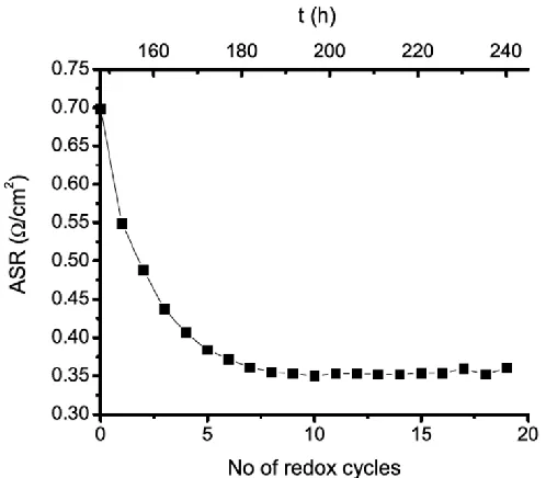
[image:2.612.178.427.383.601.2]In 2012, Verbraeken et al. presented work relating to SOFC containing Ni/CG20 and Ni/CeO2 co-impregnated LSCTA- anodes, evaluating their suitability as replacements for the Ni-based cermet standard anode material. In first-generation button cell tests, the aforementioned SOFC showed excellent redox stability and ASR which were comparable to those achieved using state-of-the-art anodes at HEXIS (Figure 1 (5)).
Figure 1. Evolution of ASR as a function of redox cycling and time for a SOFC containing a LSCTA- anode co-impregnated with 5 wt. % Ni and 10 wt. % CeO2, reported by Verbraeken et al. (5).
promising initial performance of this novel anode catalyst system, it was implemented into a full 60-cell SOFC stack within the HEXIS Galileo 1000 N micro-Combined Heat and Power (µ-CHP) unit (6). Of the nominal 1 kW power output of this unit, an impressive 700 W was attained at the first attempt of upscaling. However, over the course of ~600 hours, the power output dropped to ~250 W and the stack performance had degraded substantially. Post-mortem Scanning Electron Microscopy (SEM) revealed that thin and dense (i.e. non-optimal) anode microstructures had given rise to poor current distribution, the creation of localised temperature ‘hotspots’ and, therefore, severe agglomeration of the Ni nanoparticles up to 400 nm (6). Therefore, it was concluded that optimisation of the LSCTA- anode ‘backbone’ microstructure was required to prevent this from occurring in future stack tests. Thus, this optimisation became the initial focus of the second-generation research that we present here.
Experimental
Preparation of SOFC
SOFC were prepared by screen printing anode and cathode inks onto pre-sintered, 160 µm thick, 6 molar % scandia-stabilised-zirconia (6ScSZ) electrolytes (supplied by HEXIS)
before being sintered in air. The anode ‘backbone’ material, La0.20Sr0.25Ca0.45TiO3, supplied by Treibacher Industrie AG was sintered up to 1350 °C for 2 hours in air, whilst LSCTA- powder supplied by Praxair Specialty Ceramics was fired up to 1100 °C for 2 hours in air. State-of-the-art LSM-8YSZ/LSM (LSM = La0.76Sr0.19MnO3 (Praxair Specialty Ceramics) and 8YSZ = 8 mol. % yttria-stabilised-zirconia (Daiichi Kigenso Kagaku Kogyo Co. Ltd.)) double layer cathodes were sintered up to 1100 °C for 2 hours in air. Details of screen printing ink formulations are reported elsewhere (2,4).
SOFC employed for the ‘component variation’ testing were prepared in a similar
manner to that which is outlined above, however the composition and microstructural properties of the anode, cathode and electrolyte were altered in order to assign processes found in the AC impedance spectra of these SOFC to specific components.
Alternative Cathodes. Another LSM-YSZ/LSM cathode was produced using a LSM
powder with a smaller particle size than the ‘standard’ LSM powder (d50 = 1.1 µm vs. 1.4 µm, respectively). This cathode was also sintered up to 1100 °C for 2 hours in air. In addition, a CGO/LSCF-CGO/LSCF (LSCF = La0.60Sr0.40Co0.20Fe0.80O3+δ (Praxair Specialty Ceramics) and CGO = Ce0.90Gd0.10O1.95 (HEXIS)) triple layer cathode was screen printed and sintered in air. The CGO barrier layer was sintered up to 1225 °C for 2 hours, whilst the LSCF-CGO (50:50 wt. %) and pure LSCF components were sintered up to 1050 °C for 2 hours.
Alternative Electrolytes. Finally, a SOFC with a 8YSZ electrolyte (HEXIS) was produced in order to identify contributions, other than the ohmic resistance, that pertain to electrolyte processes.
Addition of electrocatalytically active phases to the LSCTA- anode ‘backbone’ was achieved through the process of wet impregnation. Firstly, a 0.5 M solution of the nitrate precursors of Ce0.80Gd0.20O1.90 (CG20) was produced by dissolving the required molar ratios of Ce(NO3)3.6H2O and Gd(NO3)3.6H2O (99 %, Sigma-Aldrich) in ethanol. A droplet of the solution was added to the surface of the LSCTA-anode ‘backbone’ before being dried at 80 °C and then calcined up to 500 °C for 30 minutes, to yield the CG20 component. The same process was then used impregnate the Ni, Pd, Pt, Rh and Ru metal oxide phases into the anode ‘backbone’ and details of the precursor solutions are presented in previous work (4).
Testing and Characterisation of SOFC
Short-term SOFC testing at St Andrews was carried out in a ‘sealless’ setup which
allowed the formation of a post-cell combustion zone, in accordance with the HEXIS concept and to provide comparable data to those collected in the test setups at HEXIS (4). Alumina felt gas diffusion gaskets were used to insulate the SOFC from the electrically conductive cell housing and contacting of the electrodes was achieved using Au mesh, wires and paste. SOFC were tested using a fuel gas of 3 % H2O/97 % H2 and an oxidant gas of compressed air (both at flow rates of 250 mL min-1), up to 900 °C (4). AC impedance spectra were collected at 0.8 V with an excitation amplitude of 50 mV, using a Solartron SI 1280B Electrochemical Measurement System.
Short-term and durability testing of SOFC carried out at HEXIS used similar test setups to those previously described. In this case, Au mesh (without paste) was used to contact the cathode whilst, Ni paste and mesh were used to contact the anode. The fuel gas employed was non-humidified H2 (1 % H2O/99 % H2) at a flow rate of 200 mL min-1 and the oxidant gas used was compressed air at a flow rate of 420 mL min-1. AC impedance spectra were collected at 300 mA cm-2 with an excitation amplitude of 10 mA, using a Zahner Elektrik IM6ex impedance spectrometer.
Scanning Electron Microscopy (SEM) of the LSCTA- anode ‘backbone’ microstructures was carried out using a JEOL JSM 6700F FEG-SEM.
Results and Discussion
Optimisation of the LSCTA- Anode Microstructure and Short-Term SOFC Testing
In order to prevent the previously mentioned issues with lateral electronic conductivity and poor current distribution, the LSCTA-anode ‘backbone’ microstructure as optimised using thick-film ceramic processing techniques. Information on the detailed ceramic processing of this material are reported elsewhere (2,7), however, it was found that screen printing of anode layers using a 75 wt. % LSCTA- loading ink and a 230 mesh count (per inch) screen yielded well-connected ‘backbone’ microstructures with sufficient porosity to
(2,4). Four-point DC conductivity testing of this anode microstructure (printed on a 8YSZ electrolyte) in a half-cell format indicated that an effective conductivity of 21 S cm-1 could be achieved at 900 °C or 17 S cm-1 at 850 °C (2). This was thought to be sufficient to prevent severe ohmic losses within the LSCTA-anode ‘backbone’.
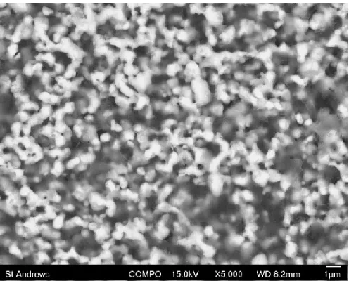
Figure 2. SEM image of the LSCTA-‘backbone’ microstructure that resulted from screen printing of a 75 wt. % solids loading ink with a 230 mesh count (per inch) screen and sintering at 1350 °C for 2 hours in air.
Subsequently, this microstructure was employed as the anode ‘backbone’ in full SOFC,
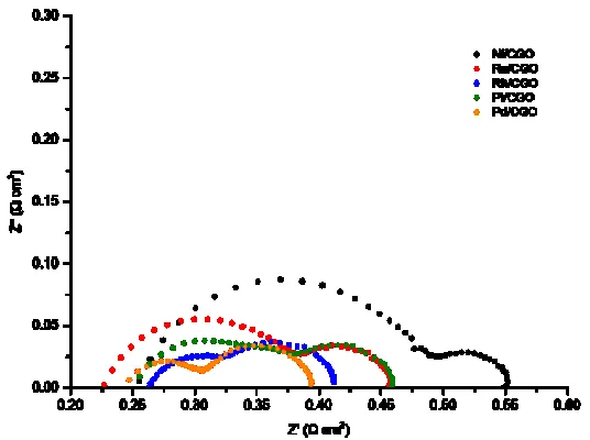
but due to the low electrocatalytic activity of this material, additional electrocatalysts were introduced using the process of catalyst co-impregnation. Here, CG20 was first added to anode microstructure, to further improve ionic and electronic conductivity, in addition to promoting reduced mobility of the metallic catalyst phase, before the metallic component was introduced to increase the TPB length available for H2 oxidation. Five co-impregnated LSCTA- anode catalyst systems (Ni/CG20, Pd/CG20, Pt/CG20, Rh/CG20 and Ru/CG20) were evaluated during short-term SOFC testing, using 3% H2O/97 % H2 as a fuel gas and compressed air as an oxidant gas. The complex plane AC impedance spectrum for each anode catalyst system, collected at 0.8 V and 900 °C, is presented in Figure 3. As previously described (4), these spectra typically exhibit 3 rate limiting processes: i) a high frequency anode charge transfer arc (2,4,5), ii) a mid-frequency cathode related process (4,8) and iii) a low-frequency gas conversion arc (4,5,9). Despite the SOFC containing the Pd/CG20 co-impregnated LSCTA- anode showing the lowest ASR (0.39 Ω cm2), the Rh/CG20 co-impregnated LSCTA- anode showed the absence of a high-frequency anode charge transfer arc, making this system particularly interesting for further development.
Assignment of Rate Limiting Processes using AC Impedance Spectroscopy
appears to elongate the lower-frequency anode charge transfer arc (fmax = 6,500 Hz). The higher-frequency process shows slight activation with increasing temperature and current density and, therefore, most likely relates to a charge transfer process. As a cathode response is not expected in this frequency domain (4), it is tentatively assigned as an anode charge transfer process. As expected, both the lower-frequency anode charge transfer process and the cathode charge transfer process are thermally activated, whilst the gas conversion process shows no temperature dependence. These assignments are further confirmed by the current sweep data which show that the anode charge transfer and gas conversion processes reduce in polarisation resistance with increasing current (and p(H2O)). The cathode charge transfer process is strongly affected by the magnitude and frequency domain of the adjacent processes, however, current density does not affect it significantly.
Figure 3. Comparative complex plane AC impedance spectra of SOFC containing a variety of metal/CG20 co-impregnated LSCTA- anodes, collected using the St Andrews test setup, at 0.8 V and 900 °C.
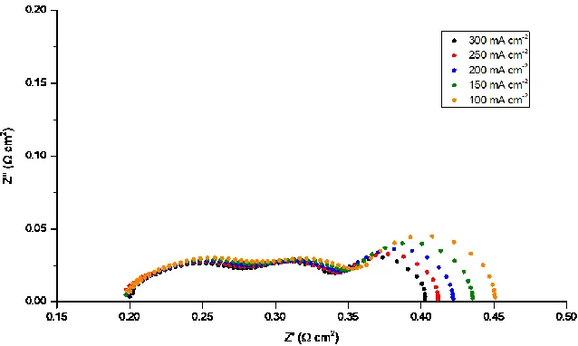
[image:6.612.138.477.472.667.2]Figure 5. Complex plane AC impedance spectra for a SOFC containing a Rh/CG20 co-impregnated LSCTA- anode, collected at 850 °C as a function of current density using the HEXIS test setups.
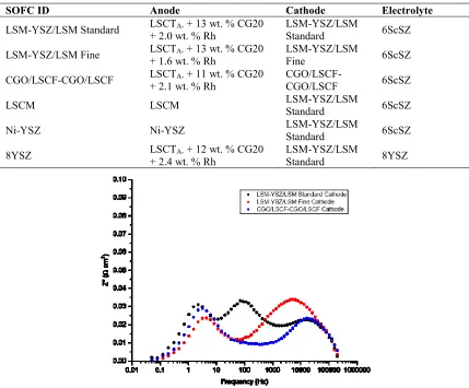
TABLE I. A summary of the components of SOFC manufactured for component variation testing.
Figure 6. Comparative Bode format AC impedance spectra showing how the magnitude and frequency domain of cathode-related process changes as a function of cathode composition and microstructure (collected at 850 °C and 300 mA cm-2 using the HEXIS test setups).
Figure 7. Comparative Bode format AC impedance spectra showing how the magnitude and frequency domain of anode-related process changes as a function of anode composition and microstructure (collected at 850 °C and 300 mA cm-2 using the HEXIS test setups).
SOFC ID Anode Cathode Electrolyte
LSM-YSZ/LSM Standard LSCT+ 2.0 wt. % Rh A- + 13 wt. % CG20 LSM-YSZ/LSM Standard 6ScSZ
LSM-YSZ/LSM Fine LSCTA- + 13 wt. % CG20
+ 1.6 wt. % Rh LSM-YSZ/LSM Fine 6ScSZ
CGO/LSCF-CGO/LSCF LSCT+ 2.1 wt. % Rh A- + 11 wt. % CG20 CGO/LSCF-CGO/LSCF 6ScSZ
LSCM LSCM LSM-YSZ/LSM Standard 6ScSZ
Ni-YSZ Ni-YSZ LSM-YSZ/LSM Standard 6ScSZ
8YSZ LSCTA- + 12 wt. % CG20
[image:8.612.179.431.495.689.2]Figure 8. Comparative Bode format AC impedance spectra showing the effect of the electrolyte material on rate limiting process of the SOFC with nominally identical anodes and cathodes (collected at 850 °C and 300 mA cm-2 using the HEXIS test setups).
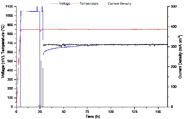
Durability Testing and Upscaling of Rh/CG20 Co-Impregnated LSCTA- Anodes
Durability testing of SOFC containing Rh/CG20 co-impregnated LSCTA- anodes was also carried out in button cell test setups at HEXIS in order to assess suitability for the upscaling process and identify typical degradation phenomena associated with these anodes, which is shown to be the component responsible for the largest polarisation resistance contribution at 850 °C, in previous sections. Figure 9 shows the change in operating voltage of a SOFC operating at 850 °C and 300 mA cm-2 over the first 160 hours of durability testing. The stability of the operating voltage at an industrially relevant current density is excellent during this time period and can give rise to degradation rates that rival those of state-of-the-art, commercial anodes under the same operating conditions. Further details of the long-term performance of the aforementioned SOFC will be presented in future manuscripts.
[image:9.612.182.428.61.251.2] [image:9.612.158.456.498.690.2]Conclusion
This manuscript has provided an overview of research relating to the development of co-impregnated La0.20Sr0.25Ca0.45TiO3 (LSCTA-) anodes at the University of St Andrews and HEXIS over the past ~10 years. It has been shown that ceramic processing of the limited conductivity perovskite LSCTA- is crucial to obtaining an optimal anode microstructure, in terms of lateral electronic conductivity and porosity for catalyst co-impregnation and gas diffusion. Furthermore, investigations into the most promising catalyst systems revealed that Rh and Ce0.80Gd0.20O1.90 (CG20) co-impregnated LSCT A-anodes exhibit excellent performance during short-term SOFC testing. Detailed AC impedance analysis suggests that the anode charge transfer process is not discernable for this anode catalyst system above 875 °C. However, at 850 °C and below, larger polarisation resistance contributions from both the anode and cathode are rate limiting. Furthermore, the assignment of arcs in the AC impedance spectra to anode, cathode and gas conversion processes was confirmed by performing systematic variations in temperature, current density and SOFC components and measuring the AC impedance response of the SOFC. Finally, an introduction to the durability testing of these SOFC has been provided, indicating high stability of the operating voltage, at 850 °C and 300 mA cm-2, over the first 160 hours of testing.
Acknowledgements
The authors would like to thank Dr Mark Cassidy and Dr Cristian D. Savaniu for providing invaluable advice on ceramic processing and conductivity measurements. In addition, the authors acknowledge funding from the University of St Andrews and HEXIS AG, as well as the EPSRC grants: EP/M014304/1 “Tailoring of Microstructural Evolution in Impregnated SOFC Electrodes” and EP/L017008/1 “Capital for Great Technologies”.
References
1. C. Sun and U. Stimming, J. Power Sources,171, 247 (2007).
2. R. Price, M. Cassidy, J. A. Schuler, A. Mai and J. T. S. Irvine, ECS Trans. 78(1), 1385 (2017).
3. A. D. A. Aljaberi, Thesis, University of St Andrews (2013).
4. R. Price, M. Cassidy, J. G. Grolig, A. Mai and J. T. S Irvine, J. Electrochem. Soc.
166, F343 (2019).
5. M. C. Verbraeken, B. Iwanschitz, A Mai and J. T. S Irvine, J. Electrochem. Soc.
159, F757 (2012).
6. M. C. Verbraeken, B. Iwanschitz, E. Stefan, M. Cassidy, U. Weissen, A. Mai and J. T. S. Irvine, Fuel Cells, 5, 682 (2015).
7. R. Price, M. Cassidy, J. A. Schuler, A Mai and J. T. S. Irvine, ECS Trans. 68(1), 1499 (2015).
8. M. J. Jørgensen and M. B. Mogensen, J. Electrochem. Soc. 148, A433 (2001). 9. S. Primdahl and M. B. Mogensen, in Proceedings of the Fifth International
Symposium on Solid Oxide Fuel Cells (SOFC-V), U. Stimming, S. C. Singhal, H. Tagawa and W. Lehnert, Editors, PV 97-40, p. 530, The Electrochemical Society Proceedings Series, Pennington, NJ (1997).
10.S. Tao and J. T. S Irvine, Nat. Mater. 2, 320 (2003).