ISSN Online: 2169-9631 ISSN Print: 2169-9623
DOI: 10.4236/ojer.2017.64009 Sep. 20, 2017 159 Open Journal of Earthquake Research
The Effective Buckling Length on Numerical
Study of Pipe-Sectioned Pier-Pile
Integral Steel Structure
Takayuki Omori, Akira Kasai, Rei Kohara
Oversea Division, Oriental Consultants Co., Ltd, Tokyo, Japan
Abstract
Pier-Pile integral structures provide construction works with many environ-mental and landscape advantages. For example, the space required to con-struct these con-structures is smaller than that of other bridges due to the footing being removed, meaning that it is not necessity to greatly change the sur-roundings of these bridges. While there are environmental and landscape ad-vantages, there are also a few demerits for the overall land-scape designs, in-cluding demerits in the design of this proposed structure which consists of relatively slender parts. This proposed structure has already been constructed in areas where possibility of a severe earthquake is low. However, some prob-lems that have yet to be examined are related to the use of this proposed structure in areas where earthquakes are frequent. Lacking detailed studies of its behavior during severe earthquakes, it is currently difficult to construct these structures in Japan. Consequently, it is necessary to investigate in detail limited performance about compression and bending moment, and earth-quake-resistant performance of these structures in order to resolve these problems. In this paper, It was clarified the relationship between the rigidity of the ground and the effective buckling length by buckling analysis and elas-to-plastic finite deformation analysis. Moreover, it was proposed a simplified formula using a proposed characteristic value β and several factors for analysis accuracy. A simplified formula would support to determine the effective buckling length to design the pier using the load-bearing capacity curve based on the slenderness ratio parameter.
Keywords
Pire-Pile Integral Steel Structures, Effective Buckling Length, Pipe Section How to cite this paper: Omori, T., Kasai,
A. and Kohara, R. (2017) The Effective Buckling Length on Numerical Study of Pipe-Sectioned Pier-Pile Integral Steel Struc-ture. Open Journal of Earthquake Research, 6, 159-167.
https://doi.org/10.4236/ojer.2017.64009
Received: August 19, 2017 Accepted: September 17, 2017 Published: September 20, 2017
Copyright © 2017 by authors and Scientific Research Publishing Inc. This work is licensed under the Creative Commons Attribution International License (CC BY 4.0).
DOI: 10.4236/ojer.2017.64009 160 Open Journal of Earthquake Research
1. Introduction
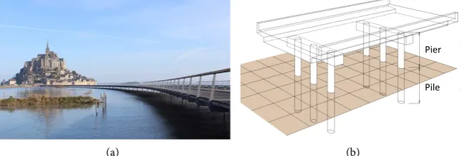
Pier-Pile integral structures provide construction works with many environ-mental and landscape advantages. For example, the space required to construct these structures is smaller because there are no footings, which avoids changing topography and protects the landscape. Some examples of the use of Pier-Pile integral structures include the pile bent pier bridge in Japan and the pedestrian bridge [1] in other parts of the world. Figure 1 shows Example of Pier-Pile integral structure. However, construction of these structures presents a few problems. In particularly, damaged areas cannot be identified after being sub-jected to a major earthquake. Therefore, it is currently difficult to construct these structures in Japan, a country where major earthquakes frequently occur. It is necessary to understand compression and bending behavior of these members, earthquake-resistant performance, and limit performance in detail in order to tackle these problems.
In accordance with the Japanese standards ([2]; herein after Japan Standard II), piers are designed based on the capacity stress obtained from the load-bearing capacity curve after designing the slenderness ratio parameter from the effective length derived from boundary condition. However, in the case of Pier-Pile integral structures, it is hard to decide the effective buckling length for calculating slenderness ratio parameter as the lower part of the pier is supported by springs. Although the effective buckling length can be calculated from the beam theory on the elastic floor, it is unsuited for practical design due to its in-convenience.
In addition, the load-bearing capacity curve of the Pier-Pile integral structure supported by the springs at the lower part is different from the application con-dition of the load-bearing capacity curve shown in the Japan Standard II, so its applicability is unclear.
In view of this background, this paper aims to clarify the relationship between the effective buckling length of the Pier-Pile integral structure and characteristic value β specified in the Japanese standards ([3]; herein after Japan Standard IV).
In this paper, the aerial part and the underground part of the Pier-Pile integral structure are referred to as “pier” and “pile” respectively.
[image:2.595.212.537.582.692.2](a) (b)
Figure 1. Example of Pier-Pile integral structure. (a) The pedestrian bridge; (b) The pile bent pier bridge.
Pier
DOI: 10.4236/ojer.2017.64009 161 Open Journal of Earthquake Research
2. The Target Structure of Study
The target structure of this study is a single column pier with its lower part sup-ported by spring. Figure 2 shows a single column pier with lower part supsup-ported by spring. It consists of a steel pipe section with an outer diameter of D = 500 mm, which is the standard size, and a thickness of 9 ≤ t ≤ 25 mm, made of SKK490 material as Electric Resistance Welded (herein after ERW) pipes. Young’s modulus of the steel is set to E = 200 GPa and Poisson’s ratio μ = 0.3.
The length of a pier is satisfied with the slenderness ratio of l/r ≤ 120 (l = Kle,
K = 1 = effective length factor, le = length of a pier h, r = cross-section secondary
radius). The slenderness ratio parameter λ and diameter-thickness ratio pa-rameter Rt satisfy the range of the following Formulas (1) and (2). This is the
range of application of pier member for satisfying the predetermined seismic performance shown in Japan Standard ([4]; herein after Japan Standard V) P228.
1
0.2 0.4
π
y l
E r σ λ
≤ = ≤ (1)
(
2)
0.03 Rt R y 3 1 0.08
t E σ
µ
≤ = − ≤ (2)
Herein, π is the circumference ratio; σy is the yield stress of material.
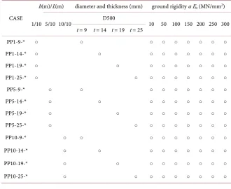
As it conforms to the Japan Standard IV, the length of pile was set at 10 m, based on βLe > 3 (β = characteristic value calculated Equation (6), Le = length of
a pile L), a semi-infinite-length pile. The ground rigidity is 10 MN/m2 ≤ αE 0 ≤
300 MN/m2. The test cases are shown in Table 1 in the form of PP h(m) −
[image:3.595.207.538.462.732.2]t(mm) − αE0 (MN/m2).
Table 1. Test cases.
CASE
h(m)/L(m) diameter and thickness (mm) ground rigidity α E0 (MN/mm2)
1/10 5/10 10/10 D500 10 50 100 150 200 250 300 t = 9 t = 14 t = 19 t = 25
PP1-9-* ○ ○ ○ ○ ○ ○ ○ ○ ○
PP1-14-* ○ ○ ○ ○ ○ ○ ○ ○ ○
PP1-19-* ○ ○ ○ ○ ○ ○ ○ ○ ○
PP1-25-* ○ ○ ○ ○ ○ ○ ○ ○ ○
PP5-9-* ○ ○ ○ ○ ○ ○ ○ ○ ○
PP5-14-* ○ ○ ○ ○ ○ ○ ○ ○ ○
PP5-19-* ○ ○ ○ ○ ○ ○ ○ ○ ○
PP5-25-* ○ ○ ○ ○ ○ ○ ○ ○ ○
PP10-9-* ○ ○ ○ ○ ○ ○ ○ ○ ○
PP10-14-* ○ ○ ○ ○ ○ ○ ○ ○ ○
PP10-19-* ○ ○ ○ ○ ○ ○ ○ ○ ○
DOI: 10.4236/ojer.2017.64009 163 Open Journal of Earthquake Research
3. Analysis Model and Method
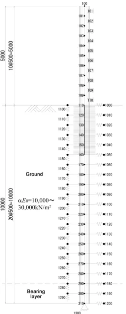
The analysis model is shown in Figure 2.
A hinged end is adopted as the boundary conditions of a pile tip. The pile part is installed with ground springs in horizontal and vertical directions. The ground spring is calculated by the formula based on the Japan Standard IV PP285-286. These equations were suggested by past experiments and analysis [5] [6] [7], have been adopting in the case of designing the pile foundation of road bridges.
3 4
0 0.3
H
H H
B
k k
−
=
(3)
0 0
1 0.3 H
k =
α
E (4)H
B
=
D
β
(5)4
4
H
k D
EI
β
=
(6)Herein kH = horizontal subgrade reaction coefficient, kH0 = horizontal subgrade
reaction coefficient corresponding to the value of the plate loading test, BH = A is
the conversion loading width of the foundation, and EI = the flexural rigidity of the steel pipe.
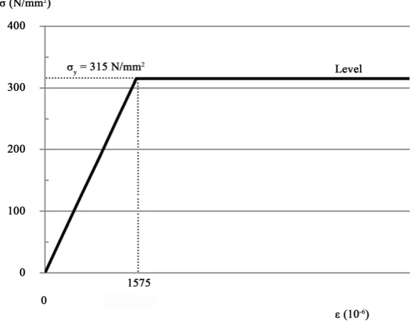
[image:5.595.231.526.477.703.2]It is confirmed that the mechanical properties of ERW (Electric Resistance Welded) pipes are higher in yield ratio than the SM material, and the secondary gradient after yield is small [8] [9] [10] [11]. This study focuses on the rigidity relationship between the ground and the piles and the entire buckling pheno-menon in the elastic region according to the effective buckling length. Therefore, the mechanical property of this material is as shown in Figure 3; the yield stress is set to 315 N/mm2, and secondary gradient is level.
DOI: 10.4236/ojer.2017.64009 164 Open Journal of Earthquake Research Effective buckling length lcr is determined from Euler’s equation using the
primary eigenvalue ω which is obtained by the eigenvalue analysis. In the analy-sis, an axial force of N = 1 kN is added to the head of the pier.
π
cr
EI l
N ω
= (7)
4. The Relationship between the Characteristic Value Beta
and the Effective Buckling Length of the Pier
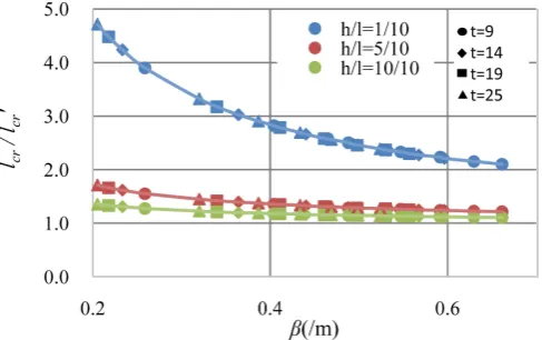
The effect that the rigidity difference between the ground and the pile has on the effective buckling length lcr is shown in Figure 4: Relationship between the
effec-tive buckling length and β. The vertical axis shows the dimensionless value re-sulting from dividing the effective buckling length lcr by the effective buckling
length lcr′ = 2 h when the lower end is fixed. The horizontal axis shows the characteristic value β indicating the relative relationship between rigidity of the soil and pile rigidity.
From Figure 4, regarding each pier length 1 m, 5 m, 10 m respectively, it can be confirmed that as β increases, namely due to the increase in rigidity of the soil compared with pile rigidity, the effective buckling length can be confirmed to approach lcr′ . Further, a blue line, which is indicating shorter pier length com-pared with whole length of Pier-Pile integral structure, is influenced from β var-iation compared with other lines.
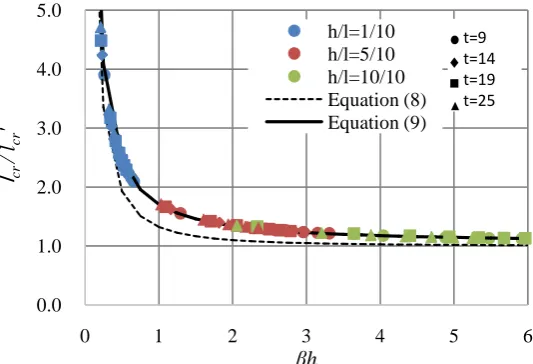
In next, due to investigate the relationship with pier length h, the horizontal axis of Figure 4 is replaced to βh which is obtained by multiplying β by h. βh is a dimensionless value indicating the ratio of h for β. It is shown in Figure 5: Rela-tionship between the effective buckling length and βh.
From Figure 5, it can be confirmed that as βh increases, the effective buckling length can be confirmed to approach lcr′ . Especially, the relationship of effective buckling length lcr and βh is represented as a continuous curve independent of
the pier length and thickness. From the above, the effective buckling length lcr of
[image:6.595.253.497.548.701.2]Pier-Pile integral structures is confirmed to be represented by the function of βh.
DOI: 10.4236/ojer.2017.64009 165 Open Journal of Earthquake Research Figure 5. Relationship between the effective buckling length and βh.
Regarding physical meaning of βh, β is the relative flexural rigidity of Beams on Elastic Foundation, the influence of β on the effective buckling length de-creases as the value of βh increases. Therefore, βh is indicating the influence rate for the effective buckling length of Pier-Pile Integral Steel Structure.
5. Estimation Formula of Effective Buckling Length
Effective buckling length of a pier with fixed supports is represented by 2h when the pier length is h. In addition, it is consistent with the point of Mmax, the
posi-tion of the fixed point, and a deflecposi-tion angle of 0 points. Figure 6 shows Effec-tive buckling length of a pier supported by fix.
Whereas, in the case of a pier supported by spring, effective buckling length differs from the point of Mmax and the deflection angle of 0 points. This is
be-cause a pile is displaced in the land surface position and deformation modes in the ground are different due to the rigidity difference between the steel pipe and the ground. Figure 7 shows Effective buckling length of a spring supported pier.
It is of note that it is assumed that the buckling mode of the pier is convex in the vicinity of the point of Mmax and that effective buckling length of the
Pier-Pile integral steel structure is indicated by Equation (8), which is twice the length of Chang equation lm [3] plus h.
(
)
(
)
1 1
1 1 1 1
2 tan 2 1.0 tan
1 2 1 2
cr
l h h
h h h
β β β β
− − + = + + +
(8)
Figure 5 shows the estimated line of Equation (8). The variation confirmed in Figure 5 is assumed to be due to the accuracy of analysis α1, and the correlation
factor α2 between the dimensionless quantity βh that affect the deformation
mode. Therefore, Equation (8) can be modified to Equation (9) using the analy-sis accuracy factor α1 and the correlation factor α2. Herein when the factors are
given as α1 = 1.05 and α2 = 0.1, the estimated line of (9) is consistent with the
analytical value of Figure 5.
0.0 1.0 2.0 3.0 4.0 5.0
0 1 2 3 4 5 6
l
cr/ l
crDOI: 10.4236/ojer.2017.64009 166 Open Journal of Earthquake Research Figure 6. Effective buckling length of a pier supported by fix.
Figure 7. Effective buckling length of a spring supported pier.
It should be noted that the correlation function is 0.999, and the standard deviation is 0.042.
(
)
1 1
2
1 1
2 1.0 tan
1 2 cr
l k
h
α
β
hα β
h−
= = + +
(9)
Herein k indicates the ratio of the effective buckling length lcr to pier height h, k would be 2.0 when the pier bottom is fixed.
6. Conclusions
The following item was revealed in this study.
• Effective buckling length lcr of Pier-Pile integral steel structures can be de-fined by the simple formula βh.
• βh is indicating the influence rate of the effective buckling length of Pier-Pile Integral Steel Structure.
• Newer concept of effective buckling length ratio k was developed.
It should be considered the applicable range of proposed formula. Especially, the ground spring was proposed to be an elastic region under the condition which is assumed that it is mainly used within a displacement of about 1% of the pile diameter. Therefore, from now on, it is planned to investigate regarding the accuracy of the ground rigidity depending on the allowable displacement amount. Moreover, for Pier-Pile integral steel structures, it was indicated the possibility for utilization of the existing load-bearing capacity curve based on the slenderness
h lm l L
lcr=2h =2lm =2l =2L
Mmax the fixed point deflection angle of 0
h h h
ground lm l L
lcr=?
Guided by Chan formula
[image:8.595.240.503.195.354.2]DOI: 10.4236/ojer.2017.64009 167 Open Journal of Earthquake Research ratio parameter using βh. As next step, it will be planned to investigate the load bearing capacity considering the effect of the largeness of the initial condition.
References
[1] Schlaichbergermann Partner: Award for the Footbridge to Le Mont Saint-Michel in France, 2016.2.
http://www.sbp.de/en/news/award-for-the-footbridge-to-le-mont-saint-michel-in-f rance-1/
[2] SPECIFICATIONS FOR HIGHWAYBRIDGES PART2 STEEL BRIDGES, Japan Road Association, 2014. (In Japanese)
[3] SPECIFICATIONS FOR HIGHWAYBRIDGES PART4 SUBSTRUCTURES, Japan Road Association, 2014. (In Japanese)
[4] SPECIFICATIONS FOR HIGHWAYBRIDGES PART5SEISMIC DESIGN, Japan Road Association, 2014 (In Japanese)
[5] The Modeling of the Horizontal Resistance of the Pile Foundation Subjected to Large Displacement, PWRI Documents Number 4100, Public Works Research In-stitute, 2008. (In Japanese)
[6] The Study on the Stable Design of Road Bridge Foundation in performance provi-sion system, PWRI documents number 4136, Public Work Research Institute, 2009. (In Japanese)
[7] PILE FOUNDATION DESIGN MANUAL, Japan Road Association, Mar., 2017. (In Japanese)
[8] Aoki, T. and Fukumoto, Y. (1981) Stocastic Material Properties and Estimate of Re-sidual Stresses of Cold-Formed-Welded Steel Tubular Members with Small Diame-ter. Proceedings of JSCE, No. 314, 39-51. (In Japanese)
[9] Nishimura, N., Takeuchi, S., Murakami, S. and Sanui, K. (1997) The Effect Manu-facturing Processes on Residual Stress and Yield Stress of ERW Pipe. Proceedings of JSSC, No. 4-13. (In Japanese)
[10] Ozoe, H., Ono, K., Nanazawa, T., Kohno, T. and Ohmori, T. (2016) An Experimen-tal Study on Ultimate Strength and Ductility of Electric Resistance Welded Pipes. The 11th German Japanese Bridge Symposium, Osaka, 30-31 August 2016, 159-160 [11] Iijima, S., Harada, T., Ohmori, T., Ozoe, H., Kohno, T. Nanazawa, T. and Ono, K.