Discussion on Strain Accommodation Associated
with Formation of LPSO Structure
Tadashi Furuhara
+and Xinfu Gu
Institute for Materials Research, Tohoku University, Sendai 980-8577, Japan
Plate-shaped precipitates accompanying change of chemical composition/order exhibit characteristics of displacive transformation when stacking sequence changes. One of intrinsic nature of long-period stacking ordered (LPSO) structures is, regular arrangements of stacking faults should cause significant change in local elastic strainfield. This study intends to discuss problems of elastic strain in associated with LPSO structure and plastic accommodation processes by diffusion. It is indicated that required time for strain accommodation through boundary diffusion is negligibly small whereas that for volume diffusion is comparable to aging time where LPSO structure are formed via precipitation from the supersaturated Mg matrix. However, high degree of coherency between the fcc-base structural unit in the LPSO structure and Mg matrix, high-speed diffusion path for diffusional accommodation cannot be provided and thus, the volume diffusion controlled process or self-accommodation by combination of structural units with alternative shears should be dominant. The observation of 14H or 10H-type LPSO structure by aging clearly indicates such strain accommodation during sequence of precipitation. [doi:10.2320/matertrans.MI201224]
(Received December 11, 2012; Accepted January 24, 2013; Published March 15, 2013)
Keywords: precipitation, interface, diffusion, strain energy, long period stacking ordered structure
1. Introduction
It has been well known that plate-shaped precipitates accompanying change of chemical composition/order exhibit characteristics of displacive transformation when stacking sequence changes.1,2) Such a transformation takes place by
the motion of interfacial defects with partial dislocation and/ or step character. Those defects were denoted as structural/ growth ledges or transformation dislocations.1,3) Later, more
general concept, i.e., transformation disconnection, was proposed.4,5)
Figure 1 shows schematically the atomic motion in front of a transformation disconnection.6) In a diffusionless/
displacive transformation (i.e., martensitic transformation), the motion of a single atom can be described by small displacement from the matrix lattice site (M) to the product lattice site (P), as is schematically shown in Fig. 1(a). Such a displacement is described as the Burgers vector associated with the transformation disconnection. However, when the partitioning of substitutional alloying elements occurs, diffusion aided by motion of vacancies around the interface needs to be involved. When a vacancy (V) is placed at a matrix site right next to the interface (Fig. 1(b)), several matrix atoms (A, B and C in thefigure) are able to jump into this site. However, the position of the adjacent site in the product phase (P) is so close to the vacancy site in the matrix. Thus, a matrix atom can jump directly into the product lattice site (Fig. 1(c)). In such a case, there are several paths for such diffusional jumps though each of them may not have the same activation energy. Although there is no one-to-one atomic correspondence, the lattice (or atomic) site corre-spondence7)accurately maintained since these jumps can be divided virtually into two components (a diffusional jump in the matrix lattice and a small displacement or shuffle from the matrix site to the product site).
The presence of one-to-one lattice site correspondence between matrix and precipitate phases results in requirement
of strain accommodation. There are several kinds of accommodation mechanisms.2) Figure 2(a) shows lattice deformation provided by pure shear. Suppose that matrix region enclosed by the dashed line in (a) is transformed by such shear without constraint from the surrounding region. Total numbers of atoms are conserved in this transformation. After the deformation, the white area becomes less in atomic density whereas the other side becomes more densely packed. Elastic accommodation first takes place but soon plastic accommodation comes in play during the growth of the
(a)
(b)
(c)
Fig. 1 Atomic site correspondence with migration of transformation disconnection at interphase boundary between matrix (M) and product (P) phases; (a) displacement of atoms by shear, (b) diffusional jumps in matrix at growth front, (c) diffusional jump from matrix lattice sites directly into a product lattice site.
+Corresponding author, E-mail: furuhara@imr.tohoku.ac.jp
Special Issue on Long-Period Stacking Ordered Structure and Its Related Materials (I)
[image:1.595.353.501.321.591.2]product phase. Plastic deformation can occur both in matrix and product phase via diffusion or deformation by slip or twinning. In Fig. 2(b), the accommodation in the matrix is described. The atomic density is recovered both in the left and right region of the product. This can be achieved by diffusion of matrix atoms from the right to the left either by bulk or interfacial diffusion. Figures 2(c) and 2(d) show that macroscopic shape of the product phase is maintained to be the same as that of the original matrix. In (c), plastic deformation of product phase occurs by dislocation slip whereas opposite shear is introduced, for example, by twinning in (d), as typically observed in ferrous martensite. Such accommodation is often seen in precipitation processes accompanying shear displacement.8)When volume change is accompanied, long-range diffusion is needed for complete relaxation.
On the formation mechanisms of long-period stacking ordered (LPSO) structure, regular arrangement of stacking faults with solute enrichment has been recognized.9) Since they provide local accumulation of strain (mostly of shear component), it is necessary to consider strain accommodation processes associated with the LPSO structures. Recently, a bi-atomic layer high stacking fault was re-examined as a four-layer high fcc structural unit with chemical ordering and two categories of LPSO structures were identified in arrangement of the structural units.10,11) However, mechanisms and
kinetics of strain accommodation should be examined further in detail. This study intends to discuss feasibility of plastic accommodation processes by diffusion because alloy parti-tioning between the LPSO structure and Mg matrix requires long-range diffusion.
2. Transformation Disconnections in fcc§hcp Trans-formation
It has been well known that transformation disconnections in fcc§hcp transformation are Shockley partial disloca-tions.12)For example, in precipitation of hcp£Aphase in the
fcc¡matrix of an AlAg alloy, the disconnection playing a role of growth ledge exists on the broad face of precipitate plates with the habit plane of (111)fcc//(0001)hcp. Howe
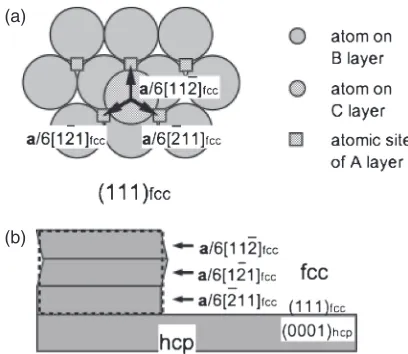
et al.13) showed that a unit growth ledge contains a a/ 6h112ifccShockley partial dislocation, promotes the stacking sequence change from fcc to hcp structure. Figure 3(a) shows schematically atomic displacement associated with Shockley partials on (111)fccplane.12)By shifting atoms on the B and C
layers to the C and A layers, respectively, two layers of hcp structure are created. Operation of a Shockley partial every other (111)fcclayer leads to thickening of hcp phase in the fcc
matrix. However, to form a single variant of hcp phase from the fcc matrix, any of three possible partials (a/6[112]fcc,
a/6[121]fcc and a/6[211]fcc) on the same (111)fccplane can
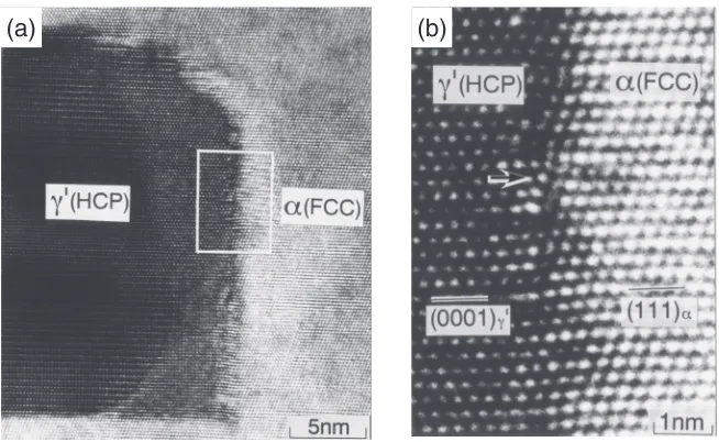
glide on every other atomic plane as seen in Fig. 3(a). Figure 3(b) shows that, if the same amount of each partial dislocation operates, the macroscopic shear strain is zero. The HRTEM micrograph of Fig. 4 shows the atomic structure of the edge of a £A plate in an Al15 mass%Ag alloy.14) This interface is formed by the coalescence of many growth ledges. By drawing Burgers circuits across this interface at various positions, it is easy to know that the three partials operate alternately in the growth of this precipitate plate. Thus, self-accommodation of transformation shear strain occurs in this transformation. On the other hand, volumetric strain is again accommodated by sessile misfit dislocations of b=a/3[111]fcc=a/2[0001]hcp (the arrow in Fig. 4). This result coincides well with that of Howe et al.13)
A bi-atomic layer high stacking fault in LPSO structure needs to contain a partial dislocations in terms of hcp Mg, equivalent to a Shockley partial in fcc structure, at its growth front. Recently, Nie and his co-workers10,11) studied precip-itation processes in Mg(Gd,Y)Zn alloys and demonstrated that originally proposed bi-atomic layer high stacking fault can be regarded as four-layer high fcc structure with chemical ordering. Although the sequence of changes in stacking and chemical composition/order is still under discussion, it is clear that the stacking change with the formation of LPSO structure accompanies large shear strain essentially.
M
P (a)
M
P (b)
M (c)
P
M
P (d)
Fig. 2 Schematic diagrams of accommodation of transformation strain (pure shear component); (a) shear strain in transformation, (b) plastic accommodation in matrix, (c) plastic accommodation in product phase by dislocation slip and (d) by twinning or formation of stacking faults accompanying shear.
(a)
(b)
Fig. 3 Description of transformation disconnection in fcc¼hcp trans-formation; (a) three equivalent shears associated with Shockley partial on (111)fccplane, (b) alternative operation of the three partials resulting in
[image:2.595.54.283.62.256.2] [image:2.595.323.527.68.245.2]3. Possibility of Diffusional Relaxation
As was mentioned in the introduction, diffusion associated with precipitation can significantly contribute to relaxation of transformation strain. Onaka and Kato15) discussed kinetics
of relaxation process by diffusion. According to them, relaxation times for boundary diffusion and volume diffusion,
¸band¸vare expressed as follows, respectively, by assuming
that particle shape is spherical and two phases have the same isotropic elastic property:
¸b¼2ð71v
5vÞ®
kTa3
Db¤ ð1Þ
¸V¼4ð13þ5vvÞ®kTa 2
DV
ð2Þ
where a: particle radius,¯: Poisson’s ratio of the matrix,®: shear modulus of the matrix, k: the Boltzmann constant,T: temperature, Db and Dv: boundary and volume diffusion
coefficients, ¤: boundary thickness and +: atomic volume, respectively. Boundary diffusion leads to accommodation of shear strain and resultant hydrostatic stressfield whereas non-conservative atomic motion promoted by volume diffusion
between the interfacial region and sinks/sources of vacancies (e.g., matrix grain boundaries) is necessary to have complete relaxation of both shear and volumetric stress components. By substituting appropriate data for pure Mg listed in Table 1,16,17) the relaxation times for both cases were
calculated. Table 2 shows the estimated time in a range of particle size suitable for LPSO structure. It was confirmed that required time for strain accommodation through boundary diffusion is negligibly small. Based upon this calculation, it appears that plastic accommodation of shear strain by diffusion can be easily established.
However, according to the Precipitation-Time-Temperature (PTT) diagram reported by Yamasaki et al.,18) £AA¼14H transition in a MgZnGd system occurs after holding of 1 h at 573 K and several minutes at 773 K. The size of LPSO structure is in orders of 10100 nm in thickness. The relaxation time for volume diffusion is comparable to the observed aging time required for formation of 14H LPSO structure. This could be understood in terms of coherency between the fcc £AA phase and the hcp Mg matrix. The (0001)hcp//(111)fccplane, which is the habit plane of£AAplate
is a lattice invariant plane in nature because of equivalent
(a)
(b)
Fig. 4 High-resolution transmission electron micrographs showing interphase boundary structures between£AAand fcc matrix in an Al 15 mass%Ag alloy:14)(a) a macroscopic view of the edge of£AA plate, (b) an enlargement of the edge revealing that there is no
[image:3.595.135.462.68.269.2]accumulation of shear strain.
Table 1 Property parameters of pure magnesium used in calculation.16,17)
Atomic volume
+/m3
Shear modulus µ/MN·m¹2
(300 K)
Poisson’s ratio¯
Volume diffusion D0/m2s-1
Volume diffusion Q/kJ·mol¹1
Grain boundary diffusion D0¤/m3·s
Grain boundary diffusion Q/kJ·mol¹1
[image:3.595.48.549.336.385.2]2.33E¹28 1.66E+04 0.29 1.0E¹04 135 5.0E¹12 92
Table 2 Calculated relaxation time by diffusional process for different temperature and size of precipitate.
Particle radius,
a
Relaxation time via boundary diffusion,
¸b/s
Relaxation time via volume diffusion,
¸v/s
423 K 573 K 773 K 423 K 573 K 773 K
1 nm 2.12E¹14 3.12E¹14 4.78E¹14 2.27E+05 1.46E+01 1.47E¹02
10 nm 2.12E¹11 3.12E¹11 4.78E¹11 2.27E+07 1.46E+03 1.47E+00
[image:3.595.46.550.420.496.2]atomic configurations. High-speed path for diffusional accommodation cannot be provided along such a boundary of good coherency and thus, the volume diffusion controlled process or self-accommodation should be dominant. For the latter case, structural units of opposite shears tend to be formed neighboring to each other as an ordinary precipitation sequence. 14H and 10H structures contain such alternative arrangements of structural units. This suggests that different Shockley partials operate in those LPSO structures formed by aging. In contrast, both of 18R and 24R structures contain fcc structural units of the same shear. Since 18R structure is rarely observed in aged specimens, local stress arising in solidification enable preferred formation of structural units of the single shear.
To understand consecutive formation of fcc structural units in LPSO structures, elastic interaction between neighboring structural units needs to be examined.
4. Strain Associated with Formation of LPSO Structure
In this section, we would like to discuss the strain associated with LPSO structure based upon Eshelby’s method.19)
The shear strain associated with the four-layer high fcc structure is about 0.089. The elastic strain energy will be calculated for different aspect ratio. Because Magnesium is nearly elastically isotropic,20) the system is assumed to be
elastic homogeneous and isotropic for simplicity, and the elastic modulus is shown in Table 1. The inclusion or precipitate is assumed to be of cuboidal shape. The cuboidal size is defined as 2b1, 2b2and 2b3alongx//[100],y//[010],
z//[001] respectively, and b1=b2. The aspect ratio is
defined as ¢=b3/b1. The elastic strain energy for different
[image:4.595.322.527.68.233.2]aspect ratio and modulus (®*=0.3®, ®*=®, ®*=3®) has been calculated by Eshelby’s method19) as shown in
Fig. 5, where ®* is the elastic modulus for precipitate. The different shear modulus applied here is going to take the chemical ordering effect in LPSO structure into account. When the aspect ratio is 0.01, the elastic strain energy is smaller than 1000 J/mol. As the aspect ratio becomes larger in Fig. 5, the elastic energy for different shear modulus increases rapidly when the aspect ratio is smaller than 0.5. Thus, thickening of precipitate is energetically unfavorable despite of the chemical ordering in LPSO. Therefore, the growth of precipitate with the same shear direction is nearly impermissible. The interaction of the plate-shaped precipitate with different shear direction is considered as following.
Suppose the infinite space contains two elastic homoge-neous and isotropic precipitates ³1 and ³2 with the
transformation strain (eigenstrain) as¾(1)and¾(2)receptively. The elastic strain energy of the system is19)
E¼ 1 2
Z
1
·ð1Þ¾ð1Þdþ
Z
2
·ð2Þ¾ð2Þdþ2
Z
1
·ð2Þ¾ð1Þd
ð3Þ
where ·(1) is the stress caused by ¾(1) and ·(2) is the stress
caused by¾(2). Since the elastic energy of a single precipitate
in an infinite space is equal to Esingle=12
R
·¾d,19) the interaction energy between³1and ³2is
Eint¼Eþ1
2 Z
1
·ð1Þ¾ð1Þdþ1 2 Z
2
·ð2Þ¾ð2Þd: ð4Þ
By substituting eq. (3) into eq. (4), eq. (4) becomes
Eint¼
Z
1
·ð2Þ¾ð1Þd: ð5Þ
For a given system, the strain is usually known, but the stress field is often complex. For the cuboidal case, the stressfields are explicitly expressed in Ref. 21), and eq. (5) can be easily calculated. Therefore, the interaction between two cuboids of the same size is considered in this study.
The elastic strain energy for a single ellipsoid or cuboidal shaped precipitate in the infinite space is shown in Fig. 6. The elastic energy in both cases increases monotonically with the aspect ratio. The elastic energy difference between two shapes is small, especially when the aspect ratio is small. The energy value in Fig. 6 will be used to compare with the interaction energy.
The overall minimum elastic strain interaction energy is reached when the shear strain of two precipitates has the opposite sign, and the precipitates closely stack with broad face to face. For example, Fig. 7 shows the variation of the interaction energy with the distance along [001] direction for
Fig. 5 Variation of the elastic strain energy with different aspect ratio and elastic modulus for a cuboidal shaped precipitate. The energy is scaled by
®¾2VwhereVis the volume of the precipitate and¾is the magnitude of
shear strain (Same for the otherfigures).
[image:4.595.321.529.295.462.2] [image:4.595.46.290.701.735.2]two cases when¢=0.1. One case shows the two precipitates with same shear direction and the other is for the two precipitates with opposite shear direction. The interaction energy cures for two cases are symmetrical as expected from eq. (5). Only the latter case has negative interaction energy, and it is energetically favorable. The interaction energy curve has a minimum, when the center distance is 2b3 i.e., two
precipitates contact. Figure 8 shows the variation of the elastic energy, the interaction energy and their ratio with the aspect ratio. The elastic strain energy in Fig. 8 is the energy when the interaction energy is not considered, i.e., the first two terms of eq. (3). The energy ratio in thisfigure shows the percentage of the energy released due to the interaction. When the aspect ratio increases, the interaction becomes weak. Thus, when the aspect ratio is small, the interaction energy should not be neglected. As shown in Fig. 8, the interaction energy could be as high as about 80% of overall elastic energy (2Esingle), i.e., 1.6Esingle. That is to say the
elastic strain energy for formation of an opposite precipitate is fully accommodated, and the extra energy (about 0.6Esingle)
is available to be the driving force.
Therefore, from the point view of elastic energy inter-action, it is confirmed that the energetically favorable LPSO structure is the one containing structural units with opposite shear neighboring to each other, such as 10H or 14H type. However, to examine origins of the variation in number of hcp Mg layers inserted between neighboring fcc structural
units, it is presumably necessary to examine chemical interaction between those units in future.
5. Conclusion
In this paper, transformation strain and feasibility of plastic accommodation by diffusion-controlled processes were discussed for formation of the LPSO structure in Mg matrix. The main conclusions are summarized in the following.
It is indicated that required time for strain accommodation through boundary diffusion is negligibly small whereas that for volume diffusion is comparable to aging time where LPSO structure are formed via precipitation from the supersaturated Mg matrix. However, because of coherency between the fcc-base structural unit in the LPSO structure and Mg matrix, slow accommodation kinetics mainly controlled by the volume diffusion or self-accommodation by combination of structural units with alternative shears should be dominant. The observation of 14H or 10H-type LPSO structure by aging clearly indicates such strain accommodation during sequence of precipitation.
Acknowledgments
This work was supported by MEXT KAKENHI Grant Number 23109006 (Grant-in-Aid for Scientific Research on Innovative Areas, “Synchronized Long-Period Stacking Ordered Structure®The Evolution of the Material Science for Innovative Development of the Next-generation Light-weight Structure Materials®”).
REFERENCES
1) H. I. Aaronson, T. Furuhara, J. M. Rigsbee, W. T. Reynolds, Jr. and J. M. Howe:Metall. Trans. A21(1990) 23692409.
2) J. W. Christian:Metall. Mater. Trans. A25(1994) 18211839. 3) B. A. Bilby: Phil. Mag.44(1953) 782785.
4) J. P. Hirth and R. C. Ponds:Acta Mater.44(1996) 47494763. 5) H. I. Aaronson, B. C. Muddle, J. F. Nie and J. P. Hirth:Metall. Mater.
Trans. A33(2002) 25412547.
6) T. Furuhara, K. Wada and T. Maki:Metall. Mater. Trans. A26(1995) 19711978.
7) J. M. Howe:Metall. Mater. Trans. A25(1994) 19171922. 8) B. C. Muddle, J. F. Nie and G. R. Hugo:Metall. Mater. Trans. A25
(1994) 18411856.
9) E. Abe, Y. Kawamura, K. Hayashi and A. Inoue:Acta Mater.50(2002) 38453857.
10) J. F. Nie, K. Oh-ishi, X. Gao and K. Hono:Acta Mater.56(2008) 60616076.
11) Y. M. Zhu, M. Weyland, A. J. Morton, K. Oh-ishi, K. Hono and J. F. Nie:Scr. Mater.60(2009) 980983.
12) T. Furuhara and T. Maki:Scr. Mater.34(1996) 929934.
13) J. M. Howe, U. Dahmen and R. Gronski:Phil. Mag. A56(1987) 3161. 14) T. Furuhara and T. Maki:Materia Japan36(1997) 483490. 15) S. Onaka and M. Kato:Mater. Sci. Eng. A146(1991) 217232. 16) Metals Data Book, ed. by Japan Inst. Metals, (Maruzen Co., Ltd., 1984)
p. 1.
17) H. J. Frost and M. J. Ashby: Deformation-Mechanism Maps, (Pergamon Press, Oxford, 1982) p. 43.
18) M. Yamasaki, M. Sasaki, M. Nishijima, K. Hiraga and Y. Kawamura: Acta Mater.55(2007) 67986805.
19) T. Mura:Micromechanics of Defects in Solids, (Martinus Nijhoff Pub., Dordrecht, 1987).
20) L. J. Slutsky and C. W. Garland:Phys. Rev.107(1957) 972976. 21) Q. Li and P. Anderson:J. Elast.64(2001) 237245.
Fig. 7 Variation of the interaction energy with the distance d between two precipitates along [001] direction when¢=0.1. The red curve is for the precipitate with opposite shear direction (see insertedfigure), while the blue curve is for the same shear direction.
[image:5.595.65.272.69.220.2] [image:5.595.64.277.285.424.2]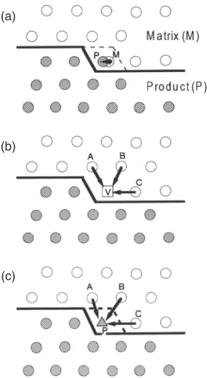

![Fig. 7Variation of the interaction energy with the distance d between twoprecipitates along [001] direction when ¢ = 0.1](https://thumb-us.123doks.com/thumbv2/123dok_us/319574.530719/5.595.64.277.285.424/fig-variation-interaction-energy-distance-d-twoprecipitates-direction.webp)