Effect of Heat Treatment Conditions on Micro Structure
of Cast Iron Coatings Sprayed by HVOF Spraying
Takayuki Kuwashima
1, Hiroshi Horie
2, Takashi Saitoh
1, Takahito Takagawa
1,
Takashi Iimura
1and Tetsuya Sonoda
11Iwate Industrial Research Institute, Morioka 020-0852, Japan 2Faculty of Engineering, Iwate University, Morioka 020-0852, Japan
Steel materials have been replaced with light material for the purpose of reducing weight of products in many industry fields. As for these light metal materials, the wear resistance and heat resistance are inferior to the steel material. The compound with the steel material is given to one of the methods for the solution of this problem.
In this study cast iron powders were sprayed on the aluminum alloy substrate using HVOF spraying method to produce composite material with excellent wear resistance property. Cast iron powder made by gas atomized method was used as spray materials and Al-Mg alloy (JIS A5083) was used as a substrate.
In thermal spraying deposition efficiency shows a decreasing trend when spray distance increases. With increasing thermal spray distance, micro Vickers hardness value decreased and mass loss of Suga type abrasive wear test and ball-on-disk wear test increased. In blast erosion test, the mass loss of their coatings increased with increasing blast angle each spray distance and in each blast angle, the mass loss of coating sprayed by distance 200 mm was smaller than other coatings. Spray material and sprayed coatings were heat-treated to examine the influence of heat treatment condition on their micro structure.
Heat treatment was carried out using electric furnace in the vacuum atmosphere of1103Pa. The heating rate was 10 K/min and holding temperature was changed between 673 and 1273 K every 200 K. The graphite phase was observed at the processing temperature of 1073 K or more.
Powder that had been heat-treated at 1073 K was then sprayed under the same conditions. Cast iron coating included graphite phase was obtained by using the thermal spray material heat-treated by 1073 K. [doi:10.2320/matertrans.47.1658]
(Received December 26, 2005; Accepted April 4, 2006; Published July 15, 2006)
Keywords: High Velocity Oxy-Fuel Spraying, cast iron, micro structure, graphite, abrasive test, heat treatment
1. Introduction
Steel materials have been replaced with light material for the purpose of reducing weight of products in many industry fields such as auto mobile industry, railway industry and so on.1–3)Especially aluminum alloys are used in many industry applications such as automotive cylinder blocks because of low density and excellent heat conduction. Wear resistance and heat resistance of these light metal materials are inferior to the steel material, so surface modification is required. For example plating method, ion plating, laser cladding method and insert method were examined to improve their abrasion resistance and corrosion resistance.4)The compound with the steel material is given as one of the methods for the solution of this problem.5–8) When aluminum alloy was welded to steel material, hard and brittle metallic compounds are formed in interface and the reliability of the joined part is low.
In other hand, cast iron has an excellent frictional property, so that this material is used for the sliding face of the machine structure.9) Graphite phase included in the cast iron is considered as cause of the excellent characteristic. In addition to sprayed cast iron coatings, sprayed coatings of cast iron with excellent wear resistance are expected to modify aluminum alloy surface.
In the micro structure of cast iron powder manufactured by atomization method, the graphite phase does not exist because the molten particles are cooled rapidly in atom-ization process.10) It is necessary to heat-treat that graphite phase is precipitated in the micro structure.
By the way there are some methods of thermal spraying
method such as flame spraying, plasma spraying and HVOF spraying and so on. HVOF sprayed coatings on aluminum alloy substrate can expect superior adhesive strength. In this study cast iron powder was sprayed on the aluminum alloy substrate using HVOF spraying method to produce compo-site material with excellent wear resistance property. And the effect of the heat treatment condition on the microstructure of sprayed coatings was also examined.
2. Experimental Procedure
2.1 Materials
Gas atomized cast iron powder was used as a spray material and SEM photograph of used powder is shown in Fig. 1 and composition and size range are listed in Table 1. The morphology of powder was like spherical and the size were 53mmunder.
Al-Mg alloy (JIS A5083) was used as a substrate and the substrates of two kinds of shape were used. One is a rod specimen (40 mmT15 mm) for using ball-on-disk wear test and the other is a plate specimen (W100 mm L75 mmT5 mm) for using other tests.
In heat-treating coatings stainless steel (JIS SUS304) was used as a substrate because treatment temperature exceeds the melting point of aluminum alloy substrate. They have been cleaned with acetone and blasted by alumina grit before thermal spraying.
2.2 Thermal spray method
High velocity oxy fuel spraying equipment manufactured by Sulzer Metco type DJ was used as thermal spraying gun.
Special Issue on Thermal Spraying
Thermal spray conditions are listed in Table 2. Propylene gas was used as a fuel gas. The graphite phase was not observed in a powder microstructure because cast iron powder was cooled rapidly at the atomization.6,11)To change the heating time by HVOF flame, spray distance has been changed. In this study three thermal spray distance 200 mm, 300 mm, 400 mm were selected to examine the influence on the coating properties to promote graphitization. The thermal spray gun was installed in six axes multiarticular robot and the gun was moved by the robot program like the ladder automatically and then thermal spray was executed by adjusting the pass number to get the required coating thickness of about 250mm. The measurement of the velocity and the surface temperature of the spray particles during the spraying were measured with TECNAR DPV-2000 system.
2.3 Heat treatment method
Spray material and sprayed coatings were heat-treated to examine the influence of heat treatment condition on their micro structure. Heat treatment was carried out using electric furnace in the vacuum atmosphere of 1103Pa. The heating rate was 10 K/min and holding temperature was changed between 673 and 1273 K every 200 K. After reach-ing at holdreach-ing temperature the specimen was cooled in the furnace slowly.
2.4 Experimental method
The test pieces were cut by precise cutting machine and molded into resin. Spray material was electroless Nickel plated to observe its micro structure easily before molding resin.10) Their surfaces were ground by automatic grinder. Etching process was implemented using the picral reagent before observation and analyzing of the coating structure. An EPMA system (made by JEOL Ltd. Model JXA-8900M) was used for the micro structure observation and composition analysis as well as X-ray diffraction device (made by Rigaku Electric, Model RINT-2200) also for the structural analysis. For the measurement of coating hardness, a micro Vickers hardness tester (made by Akashi Co., Model MVK-H100A2) was used under the load of 1.96 N and holding duration of 15 s. Measurement was made in ten sections and average value was adopted.
Schematic diagram of Suga type abrasive wear tester are shown in Fig. 2 and test condition are shown in Table 3. Suga type abrasive wear tester (made by Suga Test
Instru-Table 1 Chemical composition and size of used powder.
Composition (mass%) Size (mm)
[image:2.595.55.283.73.224.2]Fe-4C-2Si 53
Table 2 HVOF spray condition.
Oxygen Pressure (MPa) 1.0
Flow rate(L/min) 318
Propylene Pressure (MPa) 0.68
Flow rate (L/min) 66
Air Pressure (MPa) 0.48
Flow rate (L/min) 307
Spray distance (mm) 200,300,400
Traverse speed (mm/s) 750
Powder feeding rate (g/min) 30
Bed
Load
Specimen
Wheel Abrasive paper
Holder Fulcrum Load adjustment Weight
[image:2.595.310.539.75.320.2]Fig. 2 Schematic diagram of Suga-type abrasive wear tester. Fig. 1 SEM photograph of thermal spray material.
Table 3 Suga type abrasive wear test condition.
Abrasive paper SiC #320
Load (N) 4.9
Abrasive velocity (times/min) 40
Abrasive distance (mm) 30
[image:2.595.44.295.274.466.2]Abrasive cycle 4000
Table 4 Ball-on-disk wear test condition.
Abrasive material SUJ-2 steel
Rotation velocity (m/s) 0.1
Load (N) 98
[image:2.595.303.550.376.442.2] [image:2.595.303.551.479.532.2]ments Co.,Ltd. Model NUS-IS03) was used for measurement of wear resistance of coatings up to 4000 times of the abrasive cycle. In abrasive wear test, #320 SiC abrasive paper was used and examination load was 4.9 N.
Condition of ball-on-disk wear test is shown in Table 4.12) The test specimen was ground and polished before wear test. JIS SUJ-2 steel ball with diameter 5 mm was used as abrasive material.
Moreover, blast erosion test was also implemented using Arata type coating tester, which is the testing device to evaluate bonding tightness of coating particles by measuring the mass changing caused by drop-off of coating particles pulled out by blasted material.13) As the blasting material alumina of grain size of 305mm (#54) was used in one blasting shot of 70 g, which was shot out by compressed air flow of 260 kPa pressure per flow rate of 350 L/min with 30, 60, 90 degrees shot blasting angle. By weighing in the test piece after receiving each blast shot, average wear-out decreasing had to be figured out and wear-out solid volume was calculated and made this figure as wear-out velocity.
Mv¼W1=ð103W2Þ ð1Þ
Mv: wear-out velocity(m3/g),W1: mass loss(kg),W2: mass of blast material(kg),: coating density(kg/m3)
3. Results and Discussion
3.1 Effect of spray distance on coating properties
Figure 3 shows backscattered electron images and the results of characteristic X-ray map analysis of cross sections of the sprayed coatings. Pores, lamellar structures and oxide-rich layers were observed in the coatings. At thermal spray distances of 200 and 300 mm, unmelted particles were ob-served in the coatings, but in the case of a thermal spray distance of 400 mm, unmelted particles were rarely observed,
and more oxide-rich layers were observed than with other coatings.
To maintain a fixed thickness with increasing spray distance, more-pass processing was required in thermal spraying. The deposition efficiency shows a declining trend with increased spray distance. This was previously conclud-ed14) to be caused by the high occurrence of rebounding particles at greater spray distances.
The results of micro Vickers hardness tests, ball-on-disk and Suga type wear tests are shown in Fig. 4, and the results of blast erosion tests are shown in Fig. 5. With increasing thermal spray distance, the micro Vickers hardness value decreased and the mass loss during Suga type abrasive wear tests and ball-on-disk wear tests increased. The general tendency of this micro Vickers hardness test agreed with the ball-on-disk and wear test results. In blast erosion tests, the mass loss of the coatings increased with increasing blast angle at all spray distances, and at each blast angle, the mass
BEI
C-K
O-K
Fe-K
300
200
400
Spray Distance(mm)
20 m
Fig. 3 Back scattered electron images and results of characteristic X-ray map analysis of cross section of cast iron coatings.
Suga type
ball-on-disk
200 300
400 500 600 700 800 900
Spray Distance, d/mm
Micro Vickers Hardness, H
MV
400
0.8 1.2 1.6 2.0
0.38 0.40 0.42 0.44 0.46 0.48
-13
3
Mass Loss,
V
/
10
m
(ball-on-disk)
-9
3
Mass Loss,
V
/
10
m
(Suga type)
HMV
[image:3.595.128.473.73.331.2] [image:3.595.313.541.376.524.2]loss of coatings sprayed from a distance of 200 mm was smaller than for other coatings. The results of this test suggest the lower mass loss of the coating to be due to higher cohesion between the particles. The results of the wear tests
Fe
(b)
(a) Fe C
3
Fe C7 3
Fe C2
(c)
(d)
X-r
a
y
Intensity (a.u.)
Fe
Fe Fe
40 60 80 100 120 2 (degree) Cr-K 20
Fig. 6 X-ray diffraction patterns of HVOF spray coatings. (a) spray material, (b)–(d) coatings (b) sd:200 mm, (c) sd:300 mm, (d) sd:400 mm, sd:spray distance.
(a)
(b)
(c)
(d)
Fig. 7 Back scattered electron images of cross section of cast iron coatings after heat treatment (s.d. = 200 mm). (a) 673 K, (b) 873 K, (c) 1073 K, (d) 1273 K
Fe3
Fe7 3
Fe2
Graphite
Fe
X-ray Intensity (a.u.)
FeFe Fe Fe
Fe
40 60 80 100 120 2 (degree) Cr-K 673K
873K
1073K
1273K
20
C C C
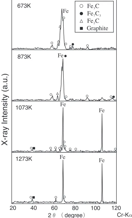
Fig. 8 X-ray diffraction patterns of HVOF spray coatings after heat treatment (s.d. = 200 mm).
30
60
90
0.2
0.4
0.6
0.8
Blast Angle, /degree
-9
3
-1
Erosion Rate
,
Mv
/10
m
g
spray distance(mm)
200
300
400
[image:4.595.311.540.70.245.2] [image:4.595.65.278.75.280.2] [image:4.595.314.535.309.688.2] [image:4.595.67.273.362.747.2]suggest a similar characteristic. We believe that the lack of an identifiable graphite phase was due to the rapid cooling of the spray particles on impact with the substrate. Next, the influence of the heating conditions on the coating structure was examined.
3.2 Influence of heating conditions on coating structure
X-ray diffraction patterns of the spray coatings are shown in Fig. 6, in which the results for the powder are also given for comparison. The spray powder shows peaks for iron and several types of carbide. There were broad peaks in the patterns of the spray powder and sprayed coatings. The results for samples at other spray distances were closely similar. Larger particles are present in the coating as unmelted particles. On the other hand, smaller particles were almost fully melted by the high velocity oxygen fuel (HVOF) flame, and these particles cooled rapidly on impact with the substrate. This means that the broader peaks resulted from the presence of supersaturated solutions of various densities,
which is in turn caused by high dissolution of carbon into iron followed by rapid cooling.
No graphite phase was observed in the sprayed coatings. Sprayed coatings were heated under various conditions to examine the effect of heating on their microstructure. Four different temperature conditions were selected, starting from 673 to 1273 K, in steps of 200 K, under vacuum. Figure 7 shows cross sections of the sprayed coatings after heat treatment. After exposure to heat treatment processing temperatures exceeding 1073 K, dark phases were observed in the coatings. From the EPMA analysis result of ‹–›
shown in Table 5, it is clear that the darker sections contain high levels of carbon. The X-ray diffraction patterns of the heat-treated coatings are shown in Fig. 8. Processing at temperatures of 1073 K or above results in sharper peaks than seen in coatings heat-treated to 873 K or less, plus a graphite peak.
Backscattered electron images and the results of map analysis of cross sections of the sprayed coatings after heat
C-K
O-K
Fe-K
BEI
[image:5.595.118.479.74.502.2]treatment are shown in Fig. 9. Unmelted particles have a semicircular shape, and a dendritic microstructure can be observed in powder cores processed at 873 K or lower. A dark layer was observed in the outer parts of the particles. Map analysis clearly shows that the X-ray intensity of O-K
in this layer is stronger than the powder core. A graphite phase was observed in coatings processed at 873 K or above. At a heat treatment temperature of 1273 K, pearlite was observed in the coating structure. Because the sprayed coating had cooled rapidly, it adopted a structure that was different from the heat-treated coatings.
Next, the spray powder was heated under various con-ditions to examine the effect of heating concon-ditions on its microstructure. The heating conditions were the same as those applied to the coatings. Figure 10 shows a cross section of the spray powder. The EPMA measurement result showing the characteristic X-ray intensity of carbon and iron (indicated by arrows) is shown in Table 5. After heat treatment at temperatures over 1073 K, numerous dark phases appeared in the spray powder. From the EPMA analysis result shown in Table 5, it is clear that the X-ray
intensity of C-Kin the darker section (fl) is higher than in the white section (fi) and that the darker section contains high levels of carbon. Figure 11 shows X-ray diffraction patterns of powder heat-treated under various conditions. A graphite peak was observed in powder heat-treated at 1073 K. It appears that the dark phase observed in the powder microstructure is a graphite phase that has precipitated from a supersaturated solid solution.
3.3 Coating structure using heat-treated powder
No graphite phase was observed in any of the coatings. Measurement of the carbon content of each coating showed the amount of decarburization due to spraying to be about 0.3 mass%. In graphitization annealing of atomized cast iron powder, Horie et al. reported10) that heating temperature influences powdery graphitization, that the graphitization time of cast iron powder is affected by the modulus (volume/ area) of the powder, and that graphite preferentially precip-itates on the free surfaces of cast iron powder. According to measurements made using the DPV-2000 system, the particle surface temperature in our experiments was about 2000 K and the particle velocity was about 250–550 m/s. The velocity of spray particles was very high and the heating time was very short. The reason for the lack of a graphite
(a)
(b)
(c)
(d)
(e)
Ni
Ni
Ni
Ni
Ni
Ni
Ni
Ni
Ni
Ni
Ni:Electroless Nickel
plated layer
Fig. 10 Back scattered electron images of cross section of cast iron powder after heat treatment. (a) as recieved, (b) 673 K, (c) 873 K, (d) 1073 K, (e) 1273 K.
20 40 60 80 100 120 2 degree Cr-K 673K
873K
1073K
1273K
Fe C3
Fe C7 3
Fe C2
Graphite
Fe Fe Fe
Fe
Fe
Fe
[image:6.595.313.539.76.448.2]X-ray Intensity (a.u.)
Fig. 11 X-ray diffraction patterns of used powder after heat treatment. Table 5 Results of EPMA analysis.
Position X-ray intensity (cps)
C-K Fe-K
Fig. 7
‹ 0 260
› 720 80
Fig. 10
fi 70 200
fl 320 85
Fig. 12
0 260
[image:6.595.54.285.215.478.2]phase in the coating was concluded to be due to the short heating time and oxidation of spray particles.
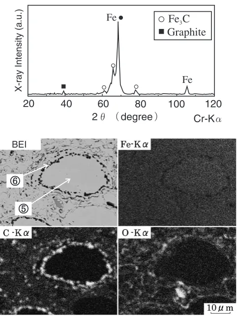
Powder that had been heat-treated at 1073 K was then sprayed under the same conditions as shown in Table 2. Figure 12 shows an X-ray diffraction pattern, backscattered electron image and the results of an X-ray map of a cross section of the coating made using powder previously heat-treated at 1073 K. Dark sections are observed in the neighborhood of unmelted particles. From the EPMA analy-sis result of –– shown in Table 5, it is evident that the darker section contains high carbon levels. In the X-ray diffraction pattern, the peaks were sharper than in as-sprayed coatings in Fig. 6, and a new graphite peak was observed. It thus appears feasible to obtain coatings including a graphite phase using heat-treated gas-atomized powder.
4. Conclusions
(1) The hardness of the coating decreases as the spraying distance increases, the abrasion loss of the wear test increases, and abrasion resistance has decreased. (2) The graphite phase was not observed in as sprayed
coatings at any spray distance. Spray distance was not affected on graphitization of spray material because impacting particles on substrate in thermal spraying were cooled rapidly. When the thermal spray material and the sprayed coatings were heat-treated, the graphite phase was observed at the processing temperature of 1073 K or more.
(3) Cast iron coating included graphite phase was obtained by using the thermal spray material heat-treated by 1073 K.
Acknowledgement
I wish to express our gratitude to Yuya Sato at Iwate University (present Nippon piston ring co., ltd). This research was supported from Science and Technology Section of the Iwate prefecture government.
REFERENCES
1) T. Egawa: Kinzoku73(2003) 119–123.
2) H. Usuki: Collected Abstracts of the 2003 Autumn Meeting of the Japan Inst. Metals (2003) 653.
3) Y. Yamagata: Collected Abstracts of the 2004 Spring Meeting of the Japan Inst. Metals (2004) 61.
4) S. Uosato: Doctoral dissertation, (Osaka University, 2003) pp. 2–6. 5) M. F. Morks, Y. Tsunekawa, M. Okuyama and M. A. Shoeib: Mater.
Trans.44(2003) 743–748.
6) T. Kuwashima, H. horie. H. Saitoh, T. Saitoh and A. Ohmori: Journal of Japan Thermal Society42(2005) 75–79.
7) M. F. Morks, Y. Tsunekawa, M. Okuyama and M. A. Shoeib: Journal of Thermal Spray Technology11(2002) 226–232.
8) Y. Tsunekawa, T. Ueno, M. Okuyama and T. Yashiro: Surface Engineering19(2003) 17–22.
9) T. Nakagawa: Journal of Japanese Society of Tribologists36(1991) 107–111.
10) H. Horie, S. Hiratsuka, T. Kowata, X. L. Shi, K. Koike and H. Endo: J. JFS73(2001) 662–667.
11) T. Kuwashima, I. Takahashi, T. Tomita and A. Ohmori: Mater. Trans.
45(2004) 1864–1868.
12) A. Iwabuchi et al.: Standard Methods for Wear, (Japan Society of Mechanical Engineers, Tokyo, 1999).
13) C. J. Li, A. Ohmori, R. Nagayama and Y. Arata: Preprints of the National Meeting of JWS.39(1986) 244.
14) C. J. Li, G. C. Ji, Y. Y. Wang and K. Sonoya: Thin Solid Films,419
(2002) 137–143.
Fe
Fe
40 60 80 100 120
2 degree Cr-K
20
X-ray Intensity (a.u.)
Fe C
3Graphite
[image:7.595.49.290.68.392.2]BEI