Coarse Columnar Structure of Transformation-Grown Ferrite in Pure Iron
—On Wrought Iron and Sintered Iron—
Hidenori Kuroki and Hiroyuki Y. Suzuki
Department of Mechanical Systems Engineering, Graduate School of Engineering, Hiroshima University, Higashi-hiroshima 739-8527, Japan
When a nucleus of ferrite crystal is formed in cast-and-rolled or sintered iron, either of which contains less than approximately 50 ppm interstitial elements, namely, carbon and nitrogen, the ferrite crystal may grow into a coarse crystal joining many austenite crystals. Furthermore, such coarse ferrite crystals may compose a columnar macrostructure by unidirectional phase transformation under the condition accompanying a gradient of temperature. The formation of the macrostructure gives a maximum linear expansion of the sample that is numerically equal to the volume expansion at the same time. Even a small amount of carbon in pure iron can cause the condensation of carbon atoms or the formation of a fairly large number of minute cementite precipitates at ferrite/austenite phase boundaries. Both the condensation of carbon and the precipitation of cementite may cause the nucleation of new ferrite crystals, leading to the development of a fine-grained macrostructure.
[doi:10.2320/matertrans.47.2449]
(Received April 21, 2006; Accepted July 31, 2006; Published October 15, 2006)
Keywords: coarse ferrite, columnar ferrite, gamma/alpha transformation, diffusional transformation, transformation growth, pure iron
1. Introduction
Many powder metallurgists are now studying pure iron due to its increasing importance in the automotive industry as a soft magnetic material for the cores of motors of electric and hybrid vehicles.1,2)Cast-and-rolled or wrought iron of ultra-high purity3)and wrought steel of the interstitial-free class4) have been developed. Powder metallurgy, however, is an easier means than wrought metallurgy for producing iron with a very low concentration of interstitial elements because sintering iron powder in vacuum or hydrogen significantly reduces both carbon and nitrogen levels. In particular, carbon is removed rapidly by the surface oxide on the powder particle in the form of CO gas. Thus, in this review, we summarize research studies of both powder metallurgy and wrought metallurgy.
When researchers investigate pure iron and very low carbon content iron, which contain interstitial elements (e.g., carbon and nitrogen) of less than approximately 50 ppm, they often encounter crystals of very coarse and columnar ferrite or transformation-grown ferrite. Such ferrite crystals are formed through the austenite/ferrite (Ar3) transformation,
which, however, is not mentioned in any textbooks. Natu-rally, researchers upon observing the optical microstructures and macrostructures of such crystals conclude that they have made a discovery.1–4)These structures, however, were in fact
reported several times5–10) in the latter half of the 20th
century, but attracted little attention from researchers since pure iron had negligible importance in the industry at that time.
Since pure iron with a very small amount of interstitial elements has found increasing usage in the industry to date, in the present review, we propose to examine the above-mentioned structures of the transformation-grown ferrite in a new light. They should be recognized as typical ferrous crystals that have the same importance as polygonal ferrite crystals formed by rolling and recrystallization.
2. Growth of Ferrite Crystals through Transformation
2.1 Coarse and fine ferrite crystals
The two photographs in Fig. 1 clearly show the suppres-sion of the coarse crystals by the presence of carbon in sintered plain iron.1)For Abiko iron,3)one of the purest types of iron available in the world today, Figure 2 shows that a decrease in the concentration of interstitial elements leads to the growth of ferrite crystals even at the ultralow concen-tration in sample (a) listed in Table 1. Another series of ferrite macrostructures, shown in Fig. 3, were reported in the mid-twentieth century in wrought pure iron sheets5)annealed
in nitrogen/wet-hydrogen mixtures. The growth of ferrite crystals would be suppressed by increased nitrogen or promoted by decarburization with increased wet hydrogen. The photographs in Fig. 4 show the correspondence between the microstructures and macrostructures of ferrite in sintered carbonyl-iron powder compacts.10) Homogenous sintered
iron with a porosity of less than 10% undergoes a trans-formation similar to that of wrought iron. Coarse columnar crystals appear in a material with less than 40 ppm carbon, and fine equiaxial crystals appear in another material with 200–300 ppm carbon. Similar coarse ferrite crystals also appear in different types of hydrogen-sintered iron from other powders of the <100 mesh class, including reduced ore, reduced mill scale and electrolytic iron powders.12)
Although the results of the analyses of carbon and nitrogen contents in sintered iron shown in Fig. 5 have not yet been reported,2)decarburization proceeds during sintering through
In sintered iron, the development of fine ferrite crystals is particularly promoted with the introduction of carbon by adding a very small amount of graphite,10)by trapping oil in
pores through soaking and repressing,13) or by transporting
carbon from a boat or a furnace structure, either of which contains a small amount of the element, through the gas phase during heating.5,13)
The effect of carbon on the above-described ferrite nucleation is illustrated in Fig. 7.10)Carbon atoms expelled from the growing ferrite are condensed at the phase boundary between ferrite and austenite. The condensation may lead to the nucleation of new ferrite crystals ahead of the growing
(a)
(b)
1mm 1mm
Fig. 1 Atomized-iron powder compacted at 600 MPa with and without graphite and cyclically sintered in vacuum at 1573 K for 1 h,1)with permission from Institute of Materials Research SAS. The powder has similar impurities to those of the atomized-iron powder shown in Table 1. (a) Plain Fe, 5 cycles. (b) Fe+0.1 mass% graphite, 2 cycles.
(a)
(b)
1mm
[image:2.595.119.478.74.197.2]Fig. 2 Ultrahigh-purity Abiko irons heated to 1363 K, forged at an austenite temperature, and cooled at continually changing rates between 800 K/s at top and 64 K/s at bottom.3)Impurities of the sample (a) are shown in Table 1. (a) 1.10 ppm C+2.1 ppm N. (b) 4.63 ppm C+14.0 ppm N.
Table 1 Impurities of iron with the highest purity and the lowest concentration of interstitial elements in each series of materials cited in this review.
Process Series of iron Impurities (ppm)
(No. of Fig.) C Si Mn P S N
Abiko (Fig. 2(a)) 1.10 1 0.01 0.01 0.73 2.1
Cast and rolled I-F-class (Fig. 6(a)) 20 500 400 20 50 38
Armco(for example) 100 10 300 10 150 —
Atomized (Fig. 5) — 40 550 50 10 —
Powder metallurgy Carbonyl (Fig. 4(a)) <10 not detected by
spectrochemical analysis <7
Impurities in a sample of Armco iron are cited from a text book11Þmerely for example. The Armco iron sample is not identical with those for Figs. 11,
14 and 15.
97%wetH2/3%N2
85%wetH2/15%N2
60%wetH2/40%N2
25%wetH2/75%N2
Fig. 3 Fast’s pure iron sheet samples heated at 1193 K for 30 min in various mixtures of ‘‘wet H2+N2’’,5)with permission from Elsevier. The
[image:2.595.130.469.254.416.2] [image:2.595.51.549.496.598.2] [image:2.595.62.277.649.748.2]ferrite before the arrival of the ferrite front. A similar illustration of and a detailed discussion on the condensation of carbon are given elsewhere4) together with Fig. 8 that
shows a TEM image of a thin cementite layer found at the ferrite grain boundary in interstitial-free iron with a very low carbon content of 20 ppm after rapid cooling.
2.2 Promotion and suppression of columnar ferrite
crystals
[image:3.595.116.481.71.317.2]The development of the columnar ferrite crystals shown in Fig. 9 began upon cooling from preexisting equiaxial ferrite crystals. The columns grow along a temperature gradient, and
(a)
(b)
(c)
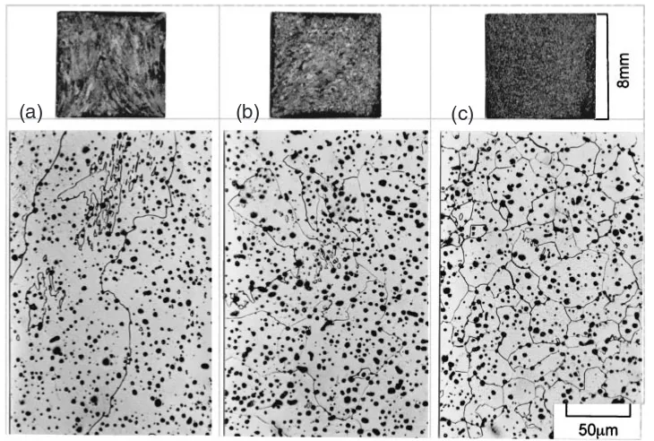
Fig. 4 Microstructures and macrostructures of ferrite in sintered carbonyl-iron powder compacts prepared for Fig. 16.10)Impurities of the sample are shown in Table 1. (a) Coarse and columnar structures, C<40ppm, N<7ppm. (b) Medium structures, C¼40{150ppm, N<7ppm. (c) Fine and equiaxial structures, C>150ppm, N<7ppm.
Fig. 5 Atomized-iron powder compacts sintered in vacuum at (a) ferrite and (b) austenite temperatures for 30 min and sectioned parallel and perpendicular to the direction of pressing.2)Impurities of the powder are shown in Table 1.
50
µ
m
Fig. 6 Interstitial-free class sheet irons cooled at 1 K/min,4)with permission from The Iron and Steel Institute of Japan. Impurities of the sample (a) are shown in Table 1. (a) 20 ppmC + 38 ppmN. (b) 100 ppmC + 40 ppmN. (c) 500 ppmC + 51 ppmN.
[image:3.595.61.279.382.542.2] [image:3.595.330.518.383.485.2] [image:3.595.119.479.668.757.2]cross the initial interface between ferrite and austenite or the initial A3 temperature line into the former austenite
crys-tals.13)The formation of the anisotropic columnar crystals is a
result of unidirectional transformation. Another example of anisotropic crystal growth appears in Fig. 10 after a massive transformation of nonferrous silver-aluminum alloy.14)When an austenite sample of pure iron with a very low carbon content is cooled, ferrite crystals that are formed at one end of the sample will continue growing by a kind of massive transformation mechanism without being substituted by other crystals. Austenite transforms into ferrite through individual
movements or diffusions of iron atoms in a very short range across the phase boundary. The formation of ferrite nuclei will be limited since the sites for such formation are few in pure iron. Thus, once a ferrite nucleus forms, it grows extremely fast.4)The growth of ferrite with fewer obstacles
will lead to the development of very coarse crystals or coarse columnar crystals joining many austenite crystals under a temperature gradient.
Even if the sum of carbon and nitrogen is approximately or less than 50 ppm, these elements will be redistributed and concentrated at advancing phase boundaries by the lever
Fig. 8 A thin cementite layer found at the ferrite grain boundary in interstitial-free iron (20 ppm C + 38 ppm N) after rapid cooling in iced brine,4)with permission from The Iron and Steel Institute of Japan. (a) Bright field image. (b) Dark field image.
α γ 1mm
40mm
A3
Line
Fig. 9 Development of columnar ferrite crystals during cooling along a temperature gradient in a carbonyl-iron powder compact kept and sintered crossing the A3temperature line in hydrogen.13)A pre-sintered/re-pressed compact similar to that for Fig. 4 (a) was sintered and
[image:4.595.118.475.73.205.2]cooled.
[image:4.595.120.477.256.471.2] [image:4.595.118.479.537.607.2]relation in the two-phase (austenite + ferrite) region, leading to the formation of compounds or the retardation of the growth of ferrite crystals. Such phase boundaries with carbon4)and nitrogen will be sites for the formation of new
ferrite nuclei, which will interrupt the development of columnar crystals and lead to the formation of equiaxial crystals. In ultrahigh-purity iron with 5 ppm carbon and 14 ppm nitrogen, lattice defects of deformed austenite also seem to become sites for the formation of ferrite nuclei that lead to the formation of equiaxial crystals.3)
3. Growth of Samples through Transformation
3.1 Growth of Armco iron samples annealed in wet
hydrogen
The unidirectional A3 transformation results in a unique
permanent dimensional change of the sample. As shown in Fig. 11, the discrepancy between differential dilatometric curves in the temperature range of the A3 transformation in
the heating and cooling courses of each wrought Armco iron sample corresponds to the type of ferritic macrostructure.6,7)
In the samples purified in hydrogen, the sample that showed a large discrepancy also showed a large permanent increase in its size and an excessive growth of ferrite crystals. In contrast, the disappearance of the discrepancy was accom-panied by the disappearance of the size increase and the formation of fine crystals. The correspondence among the transformation discrepancy in heating and cooling dilatom-etry, the size increase of samples and the growth of ferrite crystals indicates a close relationship among their mecha-nisms. The sintered plain iron sample1) with a maximum
discrepancy exhibited a maximum expansion of 0.95% during cooling transformation. This expansion is approxi-mately threefold larger than that of nonpurified Armco iron in the same report,1)0.30–0.31%. The factor of 3 suggests that
the volume expansion of iron causes a linear expansion during unidirectional cooling transformation while maintain-ing the section size of a rod sample. A coarse columnar ferritic macrostructure indicates unidirectional transforma-tion, whereas an unchanged section size suggests the restriction effect of the former austenite on the newly developing ferrite.15)
To supplement the above-mentioned papers1,6–8)on Armco
iron that give little information on the change in carbon content, the appendix of this review shows the results of our new experiments with a commercial pure iron. The as-received iron contains 40 ppm carbon and is made by a process similar to that for Armco iron. The decarburizing and homogenizing treatments of a rod sample of the iron result in a fully columnar macrostructure from the surface to the core. The columnar crystals appear in the treated iron together with a growth of the sample during furnace cooling and a reduction of the carbon content from the original value of 40 ppm to 14 ppm after treatment.
3.2 Mechanism of sample growth
To explain the correspondence between the permanent dimensional change of samples and the formation of columnar ferrite crystals, we propose the mechanism illus-trated in Fig. 12. A typical isotropic change is accompanied by equiaxial crystals, while a unidirectional change is accompanied by columnar crystals. When Ar3unidirectional
transformation begins upon cooling in an austenite bar (Fig. 13) lying along a temperature gradient, as is inevitable in most push-rod-type dilatometers, ferrite formation starts at the cool end and advances to the hot end. Under this condition, the growing ferrite area is restricted by austenite at the phase boundary since they have a common interface. The restriction results in a linear expansion of ferrite perpendic-ular to the interface, which, at maximum, is numerically almost equivalent to the volume expansion of 1.062%16)
through Ar3transformation. However, this type of restriction
is weak on growing austenite during heating or ferrite/ austenite (Ac3) transformation because of the difference in
strength, which is lower in ferrite than in austenite at the transformation temperature.15) A weaker restriction will
naturally lead to a smaller dimensional change during Ac3
[image:5.595.48.287.70.218.2]transformation. A similarly smaller change would be caused by imperfect isothermal heating in a tube furnace often used in a dilatometer. The dimensional change during the isothermal heating is equal to one-third of the volume shrinkage during the same transformation, namely, 0.354%.
Fig. 11 Differential dilatometric curves of Armco iron samples6,7)showing coarse and fine ferrite crystals, with permission from Revue de Metal-lurgie. Sizes of crystals are indicated in the former report.6)
Isotropic change
∆L ( = 0.354%L )
φ
D
L
∆L ( = 1.062%L ) L Unidirectional change φ D ∆ D/2 ∆ D/2
2∆D/D + ∆L/L = ∆V/V
[image:5.595.308.550.77.233.2]∆L/L = ∆V/V
Thus, the shrinkage of 0.354% during heating and the expansion of 1.062% during cooling induce a permanent linear expansion of a sample equal to two-thirds of the volume change, which is approximately 0.7% per cycle, with a corresponding permanent decrease in the size of the cross section, as an inevitable consequence. A clear example of this type of lengthening is shown in Fig. 14,7)which shows a pure
iron bar lengthened by 18% after 60 cycles of heating/ cooling treatment through the A3 transformation
temper-ature, with an average elongation of 0.3% per cycle. This mechanism agrees with the result reported in 193217,18)and
cited later16)as follows: ‘‘the result of repeated
transforma-tions through the A3point is to produce a permanent increase
in length, together with a decrease in cross-section’’.
3.3 Growth of iron powder compact sintered in different atmospheres
The overall appearance of the above-described trans-formation growth of samples is common to the results that were reported but not explained, namely, a group of sintered iron samples.1) Dilatometric data of atomized-iron powder
compacts sintered in different atmospheres are summarized in Table 2. The average amount of shrinkage during ferrite/ austenite (Ac3) transformation upon heating is 0.25%, which
is markedly smaller than the expansion of 0.63% of the vacuum-sintered powder compact during austenite/ferrite (Ar3) transformation upon cooling. The shrinkage of 0.25%
during the Ac3 transformation will be a result of the
shrinkage of 0.354%, as mentioned above, and a slight expansion or loosening of compacts during the same trans-formation. Ac3 transformation is assumed to proceed from
one particle to the next particle, thereby loosening the bond between them. The loosening of compacts is reflected in lateral dilatometry curves.19)
The effects of the atmosphere on the discrepancy between dimensional changes during heating and cooling transforma-tions compared with those attained under a standard rotary-pump vacuum in the same study1)are summarized as follows.
Argon at a pressure of 60 kPa, which is lower than the atmospheric pressure, slightly reduces the discrepancy. Low-pressure air further reduces the discrepancy with increasing pressure. Nitrogen at various pressures abolishes the dis-crepancy, leading to percentages of shrinkage and expansion during the transformations similar to those of Armco iron in the same report, 0.30–0.31%. The addition of 0.1 mass% graphite also abolishes the discrepancy. Thus, most of the experimental results are explained in terms of the controlling effect of small amounts of carbon and nitrogen on the growth of ferrite crystals and the discrepancy of transformation.
The effect of the atmosphere on austenite-ferrite expansion in repeated transformation cycles is shown in Fig. 15.1)There
is a possibility that the effect of atmosphere is a composite result of the dissolution and removal of interstitial atoms during sintering. For example, the reduction in expansion in Fig. 15 during repeated transformations in argon suggests first, a leakage of small amounts of air or nitrogen into the furnace atmosphere, and second, a type of carburization from the surrounding carbon containing structure, even with concentrations of 200–300 ppm, through gas-phase trans-port.13) Therefore, every possible source of leakage and contamination of the experimental apparatus, including the gas lines and dilatometer, should be checked very carefully before denying the effect of the atmosphere on repeated transformations.
∆
D/2
∆D/2
∆ L ( = 0.354%L )
φ
D
L
2∆D/D + ∆L/L = ∆V/V Isotropic Ac3 Free interface
transformation
∆ L ( = 1.062%L ) ∆L/L = ∆V/V Unidirectional Ar3
[image:6.595.47.289.74.250.2]transformation φ D L Restricting interface γ γ α α
Fig. 13 Illustration of the maximum permanent dilation of 0.708% (¼1:062%0:354%) in sample length per==cycle.
(a)
[image:6.595.304.549.115.242.2](b)
Fig. 14 An Armco-iron bar lengthened by 18% after 60 cycles of heating/ cooling treatment through the A3 transformation temperature,7) with
permission from Revue de Metallurgie. (a) Before treatment. (b) After treatment.
Table 2 Linear dimensional change at different stages of the ==
transformation cycle of atomized-iron powder compacts, heated and cooled at 10 K/min, and held at 1573 K for 1 h in various atmospheres,1Þ
with permission from Institute of Materials Research SAS.
Atmosphere Pressure at room temp., kPa
Ac3(=)
shrinkage (%)
Ar3(=)
expansion (%)
Vacuum 0.0006 0.27 0.63
Argon 60 0.23 0.57
0.01(0.008) 0.28 0.48
Air(Nitrogen) 0.02(0.016) 0.24 0.30
5(3.9) 0.24 0.28
0.02 0.26 0.29
Nitrogen 5 0.22 0.25
60 0.27 0.28
[image:6.595.54.284.303.467.2]4. Cause of Coarse Columnar Ferrite
In ferrous materials, coarse ferrite crystals are often attributed to the presence of oxygen. The results in Fig. 16 clearly show that this is not the case.10)Rather, a high oxygen content decreases the carbon content, enabling the develop-ment of ferrite columns. Table 1 shows different types of iron with the highest purity and the lowest concentration of interstitial elements in each series of materials cited in this review. Although they have a wide range of chemical compositions, they exhibit a common tendency of having coarse columnar ferrite crystals, as described above.
It is presumed by some powder metallurgists that the initial stress and strain conditions in crystals or compacts formed by cold pressing affect the sintered microstructure.1,2) Initial
ferrite crystals in a compact, however, are heated through the temperatures of recrystallization and ferrite-austenite trans-formation and held in the austenite range. The initial stress and strain conditions in such courses are eliminated through sintering in austenite and do not affect the final formation of ferrite crystals.
Thus, the formation of ferrite columnar crystals under a temperature gradient is an intrinsic result of the allotropic transformation of pure iron.
5. Conclusions
(1) Note that pure iron heated or sintered in the austenite temperature range forms ferrite crystals, which develop, not in the austenite temperature range, but throughout the austenite-ferrite transformation.
(2) Extremely coarse ferritic crystals in wrought or sintered plain iron containing less than approximately 50 ppm interstitial elements, that is, carbon and nitrogen, are associated with the intrinsic nature of the allotropic transformation of iron.
(3) Once a nucleus of ferrite crystal is formed in wrought or sintered pure iron of the above-mentioned purity, including compacts prepared from various iron powders to a density of approximately 7.1 g/cm3 or higher, it
grows into a coarse crystal joining many austenite crystals. The coarse ferrite crystals will form a columnar macrostructure by unidirectional transforma-tion under a temperature gradient giving a maximum linear expansion numerically equal to the volume expansion occurring during the same transformation. (4) Even a small amount of carbon in pure iron can cause
the condensation of carbon atoms or the formation of a fairly large number of minute cementite precipitates at ferrite/austenite phase boundaries. Both the condensa-tion of carbon and the precipitacondensa-tion of cementite may cause the nucleation of new ferrite crystals, leading to the development of a fine-grained macrostructure. (5) Repeated heating/cooling transformation cycles
through the A3 point produce a permanent increase in
length.
We wish to thank Professor H. Danninger of Tech. Univ. Vienna and Dr. S. Tajima of Toyota Central R&D Inc. for providing comments on our early works included here, Professor Abiko of Tohoku Univ. and Professor Shibata and Dr. Asakura of Univ. of Tokyo for providing their reports, and Dr. Unami of JFE Steel Corp. for performing the carbon analysis and decarburization of samples.
REFERENCES
1) H. Danninger: Powder Metall. Prog.3(2003) 75–85.
2) S. Tajima, T. Hattori, M. Kondoh, H. Okajima, M. Sugiyama and T. Kikko: Mater. Trans.46(2005) 1402–1406.
3) T. Ogawa, N. Harima, S. Takaki and K. Abiko: Mater. Trans., JIM43
(2002) 129–134.
4) K. Shibata and K. Asakura: ISIJ Int.35(1995) 982–991. 5) M. de Jong and G. W. Rathenau: Acta Metall.5(1957) 679–680. 6) P. Lehr: C. R. Acad. Sci. France242(1956) 1172–1175. 7) P. Lehr et J. P. Langeron: Rev. Metall.55(1958) 829–839.
8) C. Leymonie, Mlle Lebrun et G. Cizeron: Mem. Sci. Rev. Metall.63
(1966) 271–281.
9) Von P. Adam, H. Rohloff und G. Frohberg: Arch. Eisen.41(1970) 1153–1159.
10) H. Kuroki, Y. Kobayashi and Y. Tokunaga: J. Japan Inst. Metals41
(1977) 920–926 (Abstract and captions in English).
11) K. Monma and H. Sudo:Tekkozairyo to Sono Netsushori (Steels and Heat Treatment)(Japan Institute of Metals, 1969) p. 47 (in Japanese). 12) H. Kuroki and Y. Tokunaga: Int. J. Powder Metall. and Powder
Linear
dimens
ional c
hange
(%)
N2
Armco Ar
[image:7.595.57.284.70.237.2]Vacuum
Fig. 15 Expansion during an Ar3 transformation in repeated ==
heating/cooling cycle of atomized-iron powder compacts in different atmospheres with those of Armco iron in vacuum for reference,1)with permission from Institute of Materials Research SAS.
[image:7.595.54.284.310.466.2]Technol.20(1984) 163–170.
13) H. Kuroki, M. Shirakawa and Y. Tokunaga: J. Japan Soc. Powder and Powder Metall.22(1976) 271–278 (Abstract and captions in English). 14) J. H. Perepezko and T. B. Massalski: J. Mater. Sci.9(1974) 899–910. 15) T. Wada: Trans. Nat. Res. Inst. Metals6(1964) 153–156.
16) Z. S. Basinski, W. Hume-Rothery and A. L. Sutton: Proc. R. Soc. LondonA 229(1955) 459–467.
17) M. J. Seigle: Rev. Metall.29(1932) 169–182. 18) M. J. Seigle: Rev. Metall.29(1932) 252–258.
19) H. Kuroki: Key Eng. Mater., vol. 29–31 (Trans Tech Publication, Switzerland, 1989) pp. 365–372.
Appendix
The millsheet of a commercial pure iron called ‘‘Base Metal BMR2’’ of JFE Steel Corp. shows a carbon content of 20 ppm, which is as low as half that of the real ‘‘BMR2’’, 40 ppm, as determined by a chemical analysis of the as-received material. The as-as-received iron with 40 ppm carbon has shown coarse equiaxial ferrite crystals after tempering at 1403 K for 0.5 h in argon and Ar3 transformation during
furnace cooling. After decarburization at 1223 K for 4 h in wet hydrogen with a dew point of 323 K, a rod sample of the iron (BMR2) with a diameter of 10 mm has a carbon content of 14 ppm and a columnar crystal layer 2 mm in thickness from the surface. After subsequent homogenization at 1474 K for 24 h in argon, the iron rod with 14 ppm carbon almost completely comprises columnar crystals from the surface to the core. Both rod samples of the as-received iron with 40 ppm carbon and the decarburized and homogenized iron with 14 ppm carbon underwent their respective Ar3