Fabrication of TiB
2–FeAl Cermet by Mechanical Milling
and Subsequent Pulsed Current Sintering
Hiroyuki Nakayama, Shuji Tada, Kimihiro Ozaki and Keizo Kobayashi
Material Research Institute for Sustainable Development, National Institute of Advanced Industrial Science and Technology, 2266-98 Moriyama-ku Shimoshidami Anagahora, Nagoya 463-8560, Japan
A TiB2-FeAl cermet was successfully fabricated by the mechanical milling of TiB2, Fe and Al powders, and subsequent pulsed current
sintering. A FeAl phase was formed during the sintering process by the diffusive reaction of Fe and Al. The transverse rupture strength of the sintered sample depends on the milling condition. A suitable condition in this process was the revolution speed of 180 rpm and the milling time for 18 ks. The TiB2-40 mass% FeAl prepared from the powder milled by this condition shows a transverse rupture strength of 1370 MPa and a
hardness of 86 HRA. [doi:10.2320/matertrans.M2010434]
(Received December 27, 2010; Accepted April 18, 2011; Published June 1, 2011)
Keywords: transverse rupture strength, hardness, intermetallic compound, hard material
1. Introduction
Titanium diboride (TiB2) exhibits superior properties,
which are high hardness, high Young’s modulus, and high chemical stability. However, as a disadvantage, the TiB2is so
brittle that the consolidation of TiB2 with metal binders
ensuring the ductility of the TiB2–metal cermet has been
examined. In the previous studies, the iron group metals, Fe, Ni and Co, have been chosen.1–3) In particular, iron binder is the most economical material, but the iron group metals form borides, which is a brittle phase. In addition, the low oxidation resistance is an inevitable problem in the usage of iron binder. Therefore, a binder phase exhibiting a high chemical stability and oxidation resistance will be required in the TiB2–metal cermet.
One of the candidates for the binder fulfilling these requirements is iron aliminides. The iron aluminides having a B2 (FeAl) or D03 structure (Fe3Al) has been investigated
in the past decades because it exhibits a good oxidation resistance and is composed of common metals. In addition, it has good mechanical properties, namely, high strength and relative good ductility.4,5) Therefore, recently, these iron aluminides have been used as the binder of the TiB2–FeAl or
TiB2–Fe3Al cermets, and their superior property has been
clarified.6–8) In the case of the TiB
2–FeAl cermet, iron
aluminides exhibited good oxidation resistance. A significant weight gain due to the oxidation of the cermet by heating in the air was not observed.6)These cermets were prepared from the mixture of TiB2, Fe, and Al by mechanical milling and
subsequent pulsed current sintering (PCS). During the sintering process, molten Al and solid Fe were reacted preferably and formed a FeAl or Fe3Al binder phase;
therefore, the sintering was carried out at a relatively low temperature. In addition, the molten Al works as the sintering aid, the high relative density sintered compact is obtained. The mechanical milling also assists the binding between TiB2
and the FeAl binder phase. The mechanical milling leads to the cold welding of TiB2and the Fe phase; hence, the strong
bonding will be realized between TiB2 and the binder after
sintering.
This process is good for the fabrication of the TiB2–FeAl
cermet. However, a detailed investigation of the micro-structure and the mechanical properties of the cermet prepared by this process has not been carried out. Therefore, in this study, the fabrication of a TiB2–FeAl cermet by
mechanical milling and subsequent PCS was examined. Furthermore, the effect of the milling condition on the microstructure and the transverse rupture strength was investigated.
2. Experimental Method
The nominal composition used in this study was TiB2
-30 mass% (Fe-40 at% Al). The off-stoichiometric composi-tion of Fe-40 at% Al is selected for the binder phase because the stoichiometric FeAl composition decomposed to the FeAl and Fe2Al phases below 670 K.9)The TiB2, Fe, and Al
powders were accurately measured, and then, they were mechanically milled using a planetary ball mill (Fritsch P-4) for 3.6–108 ks in an Ar atmosphere. For the milling, a vessel (volume: 500 ml) made of chromium steel and milling media (diameter: 0.5 mm) made of cemented carbide were used. The ball-to-powder weight ratio was 0.05. The revolution speed was varied from 120 to 180 rpm, and the rotation speed was set to be 2.17 times the revolution speed. The rotation direction set in the counter to the revolution direction. After the mechanical milling, the obtained milled powders were filled into the split carbon mold having a 30 mm square shape, as shown in Fig. 1, and then consolidated using a PCS technique. The actual sintered compact is also shown in Fig. 1. The sintering was carried out at 1553 K for 120 s under 33 MPa pressure. The temperature was monitored at the surface on the punch in the vicinity of the carbon mold using a radiation thermometer as shown in Fig. 2.
was polished using diamond paper (0.5mm), and then, the microstructure was observed by SEM. The heating character-istic of the milled powder was observed using a differential temperature analysis (DTA) under an Ar flow at a heating rate of 0.33 K/s.
[image:2.595.321.534.69.291.2]3. Result and Discussion
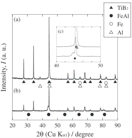
Figure 3 shows the XRD results of the powder milled at 180 rpm for 18 ks and the sintered sample prepared from the powder. The inset (Fig. 3(c)) is the enlarged graph of (a) and (b) in the range of 40–50 degree. The milled powder is composed of TiB2, Fe, and Al. A new phase formation during
the milling process is not observed. After the sintering, the sample is composed of the TiB2 and FeAl intermetallic
compound, which would be formed by the reaction between Fe and Al. The obtained FeAl phase can be indexed by a B2 structure, but the peaks slightly shift to a relatively low angle as compared to the FeAl phase listed in the powder diffraction file.10)This is because the atomic radius of Fe is larger than that of Al; hence, the lattice constant is larger than that of the FeAl in the file.10)This result is consistent with the binary alloy phase diagram in which the Fe-40 at% Al has a B2 structure below 400 K. There is no peak that corresponds to any other compound. Therefore, the sintered sample has the intended phase of TiB2 and the FeAl intermetallic
compound. In a previous research, the formation of an iron boride phase was reported in the TiB2–Fe cermet.3)However,
the suppression of the iron boride phase formation in this
study is due to the FeAl phase formation. A TiB2-FeAl
pseud-binary phase diagram reveals that the without for-mation of iron-boride phase in whole composition rage, where coexisting TiB2 and FeAl intermetallic compound
below 1700 K.11)The revolution speed and time for milling dose not affect the XRD results. That is, all the samples prepared various milling conditions in this study are composed of TiB2and the FeAl phase.
Figure 4 shows the DTA results for the powder milled at 180 rpm for 18 ks. Two significant peaks indicated by arrows are seen. The endothermic peak at approximately 930 K is observed because of the melting of Al. The exothermic reaction starts at around 1330 K and finishes at 1500 K. This peak would be caused by the reaction between molten Al and Fe for the formation of the FeAl intermetallic compound taking the route of a transition state for the
(a)
(b)
Fig. 1 Photograph of split carbon mold used in this study (a) and sintered compacted sample obtained from split mold (b).
Punch
Mold Powder
Radiation thermometer
Fig. 2 Schematic representation of the set-up for PCS.
20 30 40 50 60 70 80 90 TiB2
FeAl Fe Al
Intensity
,
I
(a. u.)
2
θ
(Cu K
α1) / degree
(a)
(b)
40 50
(c)
Fig. 3 XRD pattern of (a) milled powder at 180 rpm for 18 ks and (b) sintered sample prepared from powder of (a). Inset (c) shows enlarged graph of (a) and (b) in the range of 40–50 degree.
600 800 1000 1200 1400
DT
A (
μ
V)
Temperature,
T
/ K
5
Exo.
Endo.
[image:2.595.63.276.72.221.2] [image:2.595.103.231.274.400.2] [image:2.595.325.529.355.550.2]formation of FeAl intermetallic compound; hence, the endothermic peak is broad. A similar result has been reported by Kobayashi et al.6)In their study, the FeAl intermetallic compound was formed during a reaction between Fe and Al, and the intermediate phase formations of Fe3Al and Fe2Al5
were also confirmed in the transition for the formation of a FeAl phase sintered at 1440 K. In this study, the sintering was carried out above 1550 K, which is a sufficiently high temperature to finish the reaction for the formation of FeAl. In this process, the reaction of Fe and molten Al is utilized, thus the mixing status of each powders, in other words, the milling condition, will be affected by the mechanical properties and the microstructure. In this case, the two main factors affecting the milling conditions are the milling time and the revolution speed. Therefore, the effects of the milling time and the revolution speed on the microstructure and TRS were investigated. A change in the TRS of the sample as a function of the milling time is shown in Fig. 5. The revolution speed and the sintering temperature were fixed at 180 rpm and 1553 K, respectively. For the sake of comparison, the TRS of a sample prepared from the powder mixed by mortar is also shown in parentheses (open symbol). The increase in the milling time from 0 ks to 18 ks led to an increase in the TRS. The TRS achieves approximately 1150 MPa in the case of the milling time of 18 ks. However, a further increase in the milling time of 108 ks shows a significant decrease in the TRS, which is approximately 350 MPa.
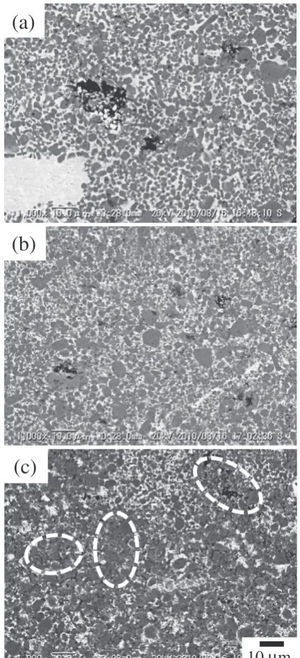
The TRS is usually related to the microstructure; hence, a change in the microstructure of the sintered sample is observed. Figure 6 shows that the microstructural evolution of the sample sintered after the milling for 0–108 ks at 180 rpm. In the case without the milling (Fig. 6(a)), a metal pool is observed. In this process, the Al melts first, and then, the molten Al and Fe show the reaction; therefore, the morphology of a binder phase depends on the size of Fe.8) The size of the Fe powder used in this study was approximately 50mm. Therefore, a large metal pool was observed. This inhomogeneous microstructure is the reason for the relative low TRS value in the sample. Meanwhile, the
metal pool was not observed in the sample prepared from the milled powders because the mechanical milling can cause the refinement of Fe. In addition, the microstructure became homogenous in the sample sintered after milling for 18 ks; hence, the TRS improved. Upon a further increase in the milling time up to 108 ks, the microstructural imhomogeneity reappeared. The area showed that TiB2 was consolidated
without a binder phase, but in the other, the fine TiB2
particles were distributed in the FeAl binder phase. It is considered that the long time milling led to the adhesion of metal powders (Fe and Al) onto the surface of the milling media and the inner wall of the vial; hence, a fraction of the binder phase would be insufficient to fill the gap between the TiB2particles. The binder-less regions observed in Fig. 6(c),
circled with broken white line, will be brittle; hence, the TRS
200 400 600 800 1000 1200
1 10 100 1000
T
ransv
erse rupture strength, TRS
/ MP
a
Milling duration, t / ks
( )
Fig. 5 Change in TRS of sintered sample as a function of milling speed of powder milled for 18 ks.
(a)
(b)
10
μ
m
(c)
[image:3.595.318.534.71.545.2] [image:3.595.69.272.73.257.2]is reduced. It is clarified that the excess milling time has an adverse effect on the TRS.
The increase in the total milling energy by the prolonga-tion of the milling speed led to the refinement of the microstructure and improvement of the TRS, but the excess milling time led to the degradation of TRS. To further refine the microstructure, the increase in the revolution speed, which leads to an enhancement of the collision energy with the ball and the powder, is examined. Figure 7 shows the effect of the revolution speed on the TRS of the sintered sample for the same milling time. The powders for these samples were milled for 18 ks at different revolution speeds. The result of the sintered sample made from the powders without mechanical milling is also indicated by the open symbol. All of the samples made from the milled powders show a higher TRS than that of the sample sintered using the powder without mechanical milling; hence, mechanical milling is effective in improving the TRS in the sintered samples. In the case of the sample prepared from the milled powders, the TRS depends upon the revolution speed. The TRS in the sample sintered after milling at 120 rpm is approximately 900 MPa. A significant improvement of the TRS was observed in the sample made from the powders milled at 150 rpm. The TRS in these samples was approx-imately 1150 MPa. Upon further increasing the revolution speed (180 rpm), we observed a slight increase in the TRS. As previously shown (see Fig. 6), a metal pool was observed in the sample prepared from the powder without milling. Meanwhile, the metal pool was not seen in all of the samples prepared from the milled powder. The disappearance of the metal pool would be a reason for the improvement of the TRS. Although the metal pool did not exist, the elongated FeAl binder phase was seen in the sample sintered from the milled powder. These irregular shapes of the FeAl phase were caused by the flattened Fe powder produced by the milling. The fraction of the irregularly shaped FeAl reduced with an increase in the revolution speed; thus, the TRS increased.
From these results, it can be observed that a suitable milling condition for the TiB2–FeAl cermet in this process
is at a rotation seed of 180 rpm for a milling time of 18 ks. The TRS of the cermet also strongly depends upon the
fraction of the binder phase; hence, the fraction of the binder phase was varied from 20–40 mass%. Figure 8 shows the change in the sintering temperature at various FeAl fractions. The plotted sintering temperature represents a relative density of more than 90% and the maximum TRS value in the samples sintered at several temperatures. The sintering temperature linearly decreases with an increase in the FeAl fraction. In this process, FeAl phase is in a solid-state, thus a small amount of FeAl is required for the flowability to the infiltration of the gap between TiB2particles under a constant
pressure (33 MPa); therefore, a relatively small amount of FeAl requires a relatively high sintering temperature to obtain a dense sample. On the basis of this temperature, the TiB2–FeAl cermet with various FeAl fractions was sintered.
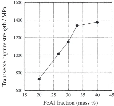
The change in the TRS as a function of the FeAl mass fraction is shown in Fig. 9. The milling condition of the powders was a revolution speed of 180 rpm and a milling time of 18 ks. The TRS increased linearly from 730 MPa with 20% FeAl to 1340 MPa with 33% FeAl. However, upon a further increase in the FeAl fraction, the improvement of the TRS was modest. Above a 40 mass% FeAl, the liquid phase of the FeAl binder leaked out from the clearance between the carbon mold and the punches in sintering; therefore, the 0
200 400 600 800 1000 1200
0 20 100 120 140 160 180 200
T
ransv
erse rupture strength, TRS
/ MP
a
Revolution speed, VR (rpm)
Fig. 7 Change in TRS of sample as a function of revolution speed.
1500 1550 1600 1650
10 15 20 25 30 35 40 45 50
Sintering temperature,
T
/ K
FeAl fraction (%)
Fig. 8 Change in sintering temperature as a function of FeAl mass fraction.
600 800 1000 1200 1400 1600
15 20 25 30 35 40 45
T
ransv
erse rupture strength / MP
a
FeAl fraction (mass %)
[image:4.595.76.261.73.242.2] [image:4.595.335.517.73.247.2] [image:4.595.332.518.290.462.2]saturated. In the PCS process, the temperature in the vicinity of the punches in the sample was higher than that of the other area. Because of the temperature distribution, the partial melting of the sintered compact in the PCS was observed, even though the average temperature was lower than that of the melting point. In addition, the change in the Rockwell hardness showed a similar trend as the TRS. That is, the HRA increased with a decrease in the FeAl fraction and saturated. Finally, the hardness of the sample with a 40 mass% FeAl cermet achieved to 86 HRA. From these results, it is clarified that the TiB2–FeAl cermet fabricated in this process realizes
both a high TRS strength and hardness by the optimization of the milling condition, sintering temperature, and FeAl fraction.
4. Conclusion
The TiB2–FeAl cermets were fabricated by the mechanical
milling of TiB2, Fe, and Al powders and the subsequent PCS.
The sintered samples were composed of TiB2 and the FeAl
intermetallic compound. The FeAl phase having the B2 structure was formed during the sintering utilizing an in-situ reaction between Fe and molten Al. The microstructure of the sintered sample depends on the milling conditions. The sintered sample prepared from the powder without milling exhibited large metal pool, but the pool was not observed in the sample sintered after milling. The sample in the TiB2–
30 mass% FeAl prepared from the powder milled for 18 ks at
the milling time led to an abrupt drop of the TRS of 340 MPa. A suitable milling condition in this process is a revolution speed of 180 rpm and a milling time for 18 ks. The TRS of the sample prepared from the powder milled under these conditions linearly increased with as increase in the FeAl binder fraction up to TiB2–33 mass% FeAl. The TRS and the
hardness in the TiB2–40 mass% FeAl were 1370 MPa and
86 HRA, respectively.
REFERENCES
1) C. B. Finch, P. F. Becher, P. Angelini, S. Baik, C. E. Bamberger and J. Brynestad: Adv. Ceram. Mater.1(1986) 50–54.
2) T. Graziani, A. Bellosi and D. D. Fabbriche: Refrac. Met. Hard Mater.
11(1992) 105–112.
3) Th. Ju¨ngling, L. S. Sigl, R. Oberacker, F. Thu¨mmler and K. A. Schwetz: Int. J. Refrac. Mat. Mater.12(1993–1994) 71–88. 4) C. T. Liu, E. P. George, P. J. Maziasz and J. H. Schneibel: Mater. Sci.
Eng. A258(1998) 84–98.
5) Y. Nishino and Y. Makino: Mater. Sci. Eng. A319–321(2001) 368– 371.
6) K. Kobayashi and K. Ozaki: Mater. Trans.47(2006) 275–278. 7) H. Nakayama, K. Kobayashi, S. Tada, M. Mikami and K. Ozaki: Mater.
Sci. Forum638–642(2009) 2138–2141.
8) H. Nakayama, K. Kobayashi, K. Ozaki and S. Tada: J. Jap. Soc. Powder Powder Metall.57(2010) 570–573.
9) T. B. Massalski, H. Okamoto, P. R. Subramanian and L. Kacprzak (ed.):Binary Alloy Phase Diagrams Second Edition, (ASM interna-tional, 1990).
10) Powder Diffraction file, #00-033-0020.