Abstract—This research aims at development of a semi-passive walking robot which can walk in good energy-efficiency even on the horizontal floor by attaching actuators to their legs. Computer simulations were carried out using the calculational model imitating the developed robot.
Then, in the computer simulations, the robot could continue to walk on the horizontal floor. In addition, improvement of knees of the developed robot was carried out. Then the control methods were examined by the experiments to check movements of the legs in the state that the body of the robot was held in the air. As the result, the movements of the four legs in the experiment were similar to those in the computer simulation when the experimental robot was operated by using the control that the two motors attached to the right and left rear-legs were synchronized with the those attached to the left and right front-legs, respectively. The experiment on walking was carried out on the horizontal floor by using the proposal control method.
Index Terms—Dynamics systems, Simulation, Walking robot, Passive walking, Quadruped walking
I. INTRODUCTION
N the recent year, many kinds of walking robots have been developed. However, most of the robots were inferior to animals on energy efficiency in walking [1]. Then, the passive walking is noticed as a method to solve the problem that the walking of a robot is inefficient than that of an animal [2]-[6].
A walking robot using the principle of passive walking can walk on the downward slope in good energy-efficiency by using potential energy like a pendulum. However, the passive walking robot cannot walk in the horizontal floor because the robot cannot use the potential energy. Then, this research aims at development of a semi-passive walking robot which can walk even on the horizontal floor in good energy-efficiency by attaching actuators to the passive walking robot [7]-[9]. In author’s previous researches, computer simulations of the passive walking robot with four legs on a downward slope were carried out. Then, the authors succeeded in letting the robot continue to walk on the downward slope. Furthermore, the passive walking robot with four legs was developed. Then, the experiment on walking
Manuscript received December 8, 2015; revised January 20, 2016.
Every author is with Mechanical Engineering Course, Graduate School of Science and Engineering, Ehime University, 3 Bunkyo-chyo, Matsuyama 790-8577, Japan
E-mail: Hiroki Iba ([email protected]), Shingo Okamoto ([email protected]), Jae Hoon Lee ([email protected])
was carried out on a downward slope. The developed robot could walk on the downward slope [10]. Then, the computer simulations where the semi-passive walking robot that installs motors walks on the horizontal floor were carried out. In the computer simulations, the robot could walk on the horizontal floor. Then, the semi-passive walking robot with four legs was developed [11]. However, the values of masses, sizes and inertia tensors of the developed robot were different from those used in the computer simulation. In this paper, the values of masses and sizes of the developed robot were measured. The inertia tensors of the developed robot were calculated by the Solid Works Ver.2014 (CAD software).
Then, the computer simulations with the measured and calculated values were carried out.In addition, improvement of knees of the developed robot was carried out. Then, the experiments to check movements of the legs were performed in the state that the body of the robot was held in the air. Then, the experiment on walking was carried out on the horizontal floor by using the proposal control method.
II. COMPUTER SIMULATION ON WALKING A. Calculational model
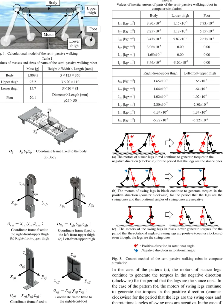
The Open Dynamics Engine (ODE) was used as a software in the current computer simulation. Fig. 1 shows the calculational model of the semi-passive walking robot. The values of the masses measured with a mass scale and the sizes measured with a ruler were used as them of parts in the computer simulation. Table 1 shows the values of masses and sizes of parts of the semi-passive walking robot. Then Fig. 2 shows the coordinate frames of parts used in calculating the inertia tensors. The solidworks (ver. 2014) that is a CAD software was used in calculating the inertia tensors of parts.
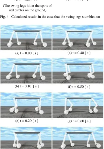
Table 2 shows the values of inertia tensors of parts of the semi-passive walking robot in computer simulation.
Collisions of the stoppers attached to the knees with the lower-thighs, and the feet with the ground were treated as the completely inelastic collision. Then, the influences due to the air resistance and the frictions at the joints of parts were ignored.
B. Method used in robot’s walking
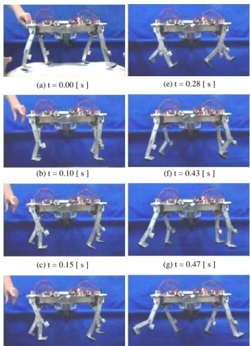
Fig. 3 shows the control method of the semi-passive walking robot in computer simulation. There are three control patterns used to control the legs of the robot, as shown in Fig.
3.The control patterns (a), (b), and (c) are described below.
Computer Simulation of Semi-Passive Walking Robot with Four Legs and Verification of It’s Validity Using Developed Experimental Robot
Hiroki Iba, Shingo Okamoto, and Jae Hoon Lee, Member, IAENG
I
xrfl
zrfl
orfl
yrfl
rfl:
rfl rfl
rfl x y z
o
Coordinate frame fixed to the right-front-lower thigh
(d) Lower thigh
In the case of the pattern (a), the motors of stance legs continue to generate the torques in the negative direction (clockwise) for the period that the legs are the stance ones. In the case of the pattern (b), the motors of swing legs continue to generate the torques in the positive direction (counter clockwise) for the period that the legs are the swing ones and the rotational angles of swing ones are negative. In the case of the pattern (c), the motors of the swing legs never generate the torques for the period that the rotational angles of swing legs are positive (counter clockwise) even thought the legs are the swing ones.
Motor
Upper thigh
Lower thigh
Foot Body
TableI
Values of masses and sizes of parts of the semi-passive walking robot Mass [g] Height×Width×Length [mm]
Body 1,809.3 5×125×350
Upper thigh 93.2 3×20×110
Lower thigh 15.7 3×20×81
Foot 20.1 Diameter×Length [mm]
φ26×50
b:
b b
b x y z
o Coordinate frame fixed to the body (a) Body
Table II
Values of inertia tensors of parts of the semi-passive walking robot in computer simulation
Body Lower thigh Foot
Jxx [kg・m2] 3.30×10⁻² 1.15×10⁻⁵ 7.73×10⁻⁶ Jyy [kg・m2] 2.25×10⁻³ 1.12×10⁻⁵ 5.35×10⁻⁶ Jzz [kg・m2] 3.47×10⁻² 5.87×10⁻⁷ 2.63×10⁻⁶
Jxy [kg・m2] 3.06×10⁻⁵ 0.00 0.00
Jxz [kg・m2] -1.65×10⁻⁷ 0.00 0.00 Jyx [kg・m2] 3.46×10⁻⁵ -3.20×10⁻⁷ 0.00
Right-front-upper thigh Left-front-upper thigh Jxx [kg・m2] 1.65×10⁻⁴ 1.65×10⁻⁴ Jyy [kg・m2] 1.64×10⁻⁴ 1.64×10⁻⁴ Jzz [kg・m2] 1.02×10⁻⁵ 1.02×10⁻⁵ Jxy [kg・m2] 2.80×10⁻⁷ -2.80×10⁻⁷ Jxz [kg・m2] -1.34×10⁻⁵ 1.34×10⁻⁵ Jyx [kg・m2] -5.22×10⁻⁶ -5.22×10⁻⁶
(a) The motors of stance legs in red continue to generate torques in the negative direction (clockwise) for the period that the legs are the stance ones
(b) The motors of swing legs in black continue to generate torques in the positive direction (counter clockwise) for the period that the legs are the swing ones and the rotational angles of swing ones are negative
(c) The motors of the swing legs in black never generate torques for the period that the rotational angles of swing legs are positive (counter clockwise) even thought the legs are the swing ones
: Positive direction in rotational angle : Negative direction in rotational angle
Fig. 3. Control method of the semi-passive walking robot in computer simulation
xrfu
zrfu
orfu
yrfu
rul:
rul rul
rul x y z
o
Coordinate frame fixed to the right-front-upper thigh (b) Right-front-upper thigh
xlfu
zlfu
olfu
ylfu
lfu :
lfu lfu
lfu x y z
o
Coordinate frame fixed to the left-front-upper thigh (c) Left-front-upper thigh
rff :
rff rff
rff x y z
o
Coordinate frame fixed to the right-front-foot
(e) Foot
xrff
zrff
orff
yrff Fig. 1. Calculational model of the semi-passive walking
Fig. 2. Coordinate frames of parts used in calculating the inertia tensors
C. Calculated results
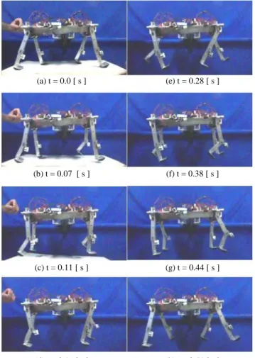
Fig. 4 shows the calculated results in the case that the swing legs stumbled on the ground. The swing legs stumbled on the ground due to the low initial speed of the robot, the low torque of swing legs, and the inappropriate timing of the generated torque. Then the robot was able to continue to walk by changing the initial speed of the robot and the torque of motors attached to the swing legs. Fig. 5 shows the calculated results in the case that the semi-passive walking robot was able to continue to walk.
III. DEVELOPMENT OF THE EXPERIMENTAL SEMI-PASSIVE WALKING ROBOT
A. Configuration of hardware
Fig. 6 shows the experimental semi-passive walking robot.
The robot comprises the body and the four legs with the knee.
The each leg comprise the upper-thigh, the lower-thigh, the stopper to which the electromagnet was attached, and the foot.
The stopper attached to the upper-thigh is used for the purpose that the lower-thigh may not rotate in an excessive rotational angle. Four motors as total by one in each the leg were attached at the four joints between the body and the legs.
The torque was given to the each leg by the motor.
B. Control system of the experimental robot
Fig. 7 shows the configuration of control system of the experimental semi-passive walking robot. The robot was controlled by both the main-micro controller and the sub-micro one. The rotational angles measured by the encoders attached to the motors on the right-front and left-front legs were transmitted to the main-micro controller.
Fig. 4. Calculated results in the case that the swing legs stumbled on the ground
(b) t = 0.10 [ s ]
(c) t = 0.20 [ s ] (a) t = 0.00 [ s ]
(e) t = 0.40 [ s ]
(f) t = 0.50 [ s ] (d) t = 0.30 [ s ]
(The swing legs hit at the spots of red circles on the ground)
(e) t = 0.40 [ s ]
(b) t = 0.10 [ s ] (a) t = 0.00 [ s ]
(c) t = 0.20 [ s ] (g) t = 0.60 [ s ] (f) t = 0.50 [ s ]
(d) t = 0.30 [ s ] (h) t = 0.70 [ s ] Fig. 5. Calculated results in the case that the semi-passive walking robot continued to walk
Upper thigh Body
Lower thigh Electro
magnet
& Stopper Motor
Electro magnet
& Stopper Motor
Foot Fig. 6. Experimental semi-passive walking robot
Fig. 7. Configuration of control system of the experimental semi-passive walking robot
While, the rotational angles measured by encoders attached to the motors on the right-rear and left-rear legs were transmitted to the sub-micro controller. Then, the rotational angles of the rear legs were transmitted from the sub-micro controller to the main-micro controller. The motors were controlled in every 1 milliseconds by the main-micro and sub-micro controllers.
The rotational angle of each the leg measured by the encoder was saved in the main-micro controller, and transmitted with the Bluetooth communication to the PC.
C. Improvement of the robot legs
Fig. 8 shows the lower-thigh’s rebound against the stopper attached on the upper-thigh in the experiment where the semi-passive walking robot was operated in the air. In the computer simulation, the lower-thigh did not rebound against the stopper because the collision was treated as the completely inelastic collision. Then, the legs were improved so that the lower-thigh may not rebound against the stopper in the experimental robot. Fig. 9-(a) shows the state that the leg before improvement bends the knee. Fig. 9-(b) shows the state that the leg improved by attaching the electromagnet to the knee bends the knee. The rebound of the knee could be suppressed by the magnetic force of the electromagnet when the lower-thigh collided with the knee. Fig. 10 shows the Leg in the case that rebound of the knee was suppressed by the magnetic force.
Fig. 8. Lower-thigh’s rebound against the stopper attached on the upper-thigh in the experiment where the semi-passive walking robot was operated in the air
(The lower-thigh hits the stopper in the red circle spot)
Electro magnet
Fig. 9. Improvement of the knee of experimental robot
Fig. 10. Leg in the case that rebound of the knee is suppressed by the magnetic force
Support to hold the robot
Fig. 11. Setting of initial posture of the four legs of robot in the experiment to check motions of the legs in the air
(b) t = 0.10 [ s ] (a) t = 0.00 [ s ]
(c) t = 0.15 [ s ]
(f) t = 0.43 [ s ] (e) t = 0.28 [ s ]
(d) t = 0.20 [ s ]
(g) t = 0.47 [ s ]
(h) t = 0.55 [ s ]
Fig. 12. Experimental result in the case that four legs were independently moved using each the encoder on the motor in the air
(a) State that the leg before improvement bends the knee
(b) State that the leg improved by attaching the electromagnet to the knee bends the knee
IV. EXPERIMENT TO CHECK MOTIONS OF LEGS OF THE ROBOT
A. Experimental method
Fig. 11 shows the setting of initial posture of the four legs of robot in the experiment to check motions of the legs in the air. The robot to which the initial posture was given was held by the support to hold the robot in the air. The same initial posture as that in the computer simulation was given to the robot. The robot can start to walk when pushing on the switch attached to the rear end of the body. The robot can move the legs in the air when the board fixing the posture of the robot is released at the same time that the legs start to move.
B. Result in the case that the four legs were independently moved
Fig. 12 shows the experimental result in the case that four legs were independently moved using each the encoder on the motor in the air. The torques of the four motors were given to the legs by using the rotational angle measured by the encoder and the angular velocity calculated from the measured rotational angle. At the first stage of motion, the legs of robot could move like the result of the computer simulation. Then the timing of motions of the legs at the diagonal position was gradually deviating with the lapse of time.
C. Result in the case that the legs at the diagonal position were synchronized
Fig. 13 shows the experimental result in the case that right and left hind-legs were synchronized with left and right front-legs respectively. The front-legs independently move using the encoders on their motor in the air. The torques of two motors attached to the right and left front legs were given to their legs by using the rotational angle measured by the encoders and the angular velocity calculated from the measured rotational angle. The motors attached to the Fig. 15. Experimental result in the case that the robot was walking on the horizontal floor where right and left hind-legs were synchronized with left and right front-legs respectively and front-legs independently move using the encoders on their motor
Fig. 14. Device to push the robot in order to give an initial speed (b) t = 0.07 [ s ]
(a) t = 0.0 [ s ]
(c) t = 0.11 [ s ]
(f) t = 0.38 [ s ] (e) t = 0.28 [ s ]
(d) t = 0.16 [ s ]
(g) t = 0.44 [ s ]
(h) t = 0.51 [ s ]
Fig. 13. Experimental result in the case that right and left hind-legs were synchronized with left and right front-legs respectively. The front-legs independently move using the encoders on their motor in the air
(b) t = 0.23 [ s ] (a) t = 0.00 [ s ]
(c) t = 0.30 [ s ]
(f) t = 0.52 [ s ]
(e) t = 0.44 [ s ] (d) t = 0.36 [ s ]
(g) t = 0.58 [ s ]
(h) t = 0.69 [ s ]
(j) t = 0.77 [ s ] (i) t = 0.72 [ s ]
rear-left and front-right legs were synchronized. The motors attached to the rear-right and front-left legs were also synchronized. The four legs of robot could continue to move like the result of the computer simulation by synchronizing the two motors on the legs at the diagonal position.
V. EXPERIMENT ON WALKING OF THE ROBOT ON THE HORIZONTAL FLOOR
A. Experimental method
Fig. 14 shows the device to push the robot in order to give an initial speed. The robot starts to walk when the switch to start control is pushed by the device to push the robot. The initial speed must be given to the robot so that the robot can walk as the computer simulation. Then the experiment on walking was carried out after the initial speed was given by using the device to push the robot.
B. Experimental result
Fig. 15 shows the experimental result in the case that the robot was walking on the horizontal floor where right and left hind-legs were synchronized with left and right front-legs respectively and front-legs independently move using the encoders on their motor. The robot was able to walk by two steps on the horizontal floor in the current method.
VI. CONCLUSION
The summaries of the results are shown below.
(1) The computer simulation was carried out using the calculational model imitating the developed robot. The robot could continue to walk in the computer simulation.
(2) The rebound of the lower-thigh of the experimental robot after it collides with the stopper attached on the knee, could be suppressed by the improvement (the electromagnet was attached to the knee) of the knee.
(3) The movements of the four legs in the experiment were different from those in the computer simulation when the experimental robot was operated without synchronizing the four motors attached to the four legs in the air.
(4) Then, the movements of the four legs in the experiment were similar to those in the computer simulation when the experimental robot was operated by using the control that the two motors attached to the right and left rear-legs were synchronized with the those attached to the left and right front-legs, respectively in the air.
(5) The experiment on walking was carried out on the horizontal floor by using the proposal control method. The robot was able to walk by two steps.
In the future works, adjustment of the torque to be given the legs and improvement of the control method will be carried out to continue the walking of the robot.
REFERENCES
[1] K. Ono, R. Liu, “Optimal Biped Walking Locomotion Solved by Trajectory Planning Method,” Journal of Dynamic Systems, 124:554–565,( 2002)
[2] T. McGeer, “Passive Dynamic Walking,” The International Journal of Robotics Research, 9:2:62-82, (1990)
[3] T. McGeer, “Passive Walking with Knees,” Proceeding of the IEEE Conference on Robotics and Automation,2: 16450-16451,(1997) [4] Q. Wu, N. Sabet, “An Experimental Study of Passive Dynamic
Walking,” Robotica, 22.03: 251-262, (2004)
[5] Poulakakis, Ioannis, Evangelos Papadopoulos, Martin Buehler, “On the Stability of the Passive Dynamics of Quadrupedal Running with a Bounding Gait,” The International Journal of Robotics Research, 25.7: 669-687, (2006)
[6] Qi. Deng, et al, “Quasi Passive Bounding of a Quadruped Model with Articulated Spine Mechanism and Machine Theory”,52:232-242, (2012)
[7] K. Tani, S. Okamoto, JH. Lee, H. Koike, “Simulations on Motion Control and Development of Biped Walking Robot,” Proceeding of the International Multi Conference of Engineers and Computer Scientists, 2:916 -919, (2012)
[8] H. Koike, JH. Lee, S. Okamoto, “Optimized Walking Control of a Biped Walking Robot Considering Theory of a Pendulum,”
Proceeding of the Artificial Life and Robotics, 352-355, (2013) [9] T. Yamada, S. Okamoto, JH. Lee, “Semi-passive Biped Robot Using
Motion Control Combining Energy and PD Controls,” Proceeding of the International Multi Conference of Engineers and Computer Scientists, Vol. 1, (2014)
[10] K. Yamashita, S. Okamoto, JH. Lee, “Simulation and Experiment on Walking of Passive Walking Robot Having Four-legs with Knees,”
Proceedings of the Annual Meeting of the Japan Society of Mechanical Engineers Chugoku-Shikoku Regional Student Division,(2012)
[11] Tamura W, Okamoto S, Lee JH,“Simulation and Experiment on Level Ground Walk of Semi-Passive Walking Robot with Four Legs”,
Proceedings of the Annual Meeting of the Japan Society of Mechanical Engineers Chugoku-Shikoku Regional Student Division,(2013)