warwick.ac.uk/lib-publications
A Thesis Submitted for the Degree of PhD at the University of Warwick
Permanent WRAP URL:
http://wrap.warwick.ac.uk/106984
Copyright and reuse:
This thesis is made available online and is protected by original copyright.
Please scroll down to view the document itself.
Please refer to the repository record for this item for information to help you to cite it.
Our policy information is available from the repository home page.
THE BRITISH LIBRARY
BRITISH THESIS SERVICE
T IT L E
A VARIABLE STRUCTURE SPACE VOLTAGE
VECTOR CONTROLLED SWITCHED
RELUCTANCE FLUX VECTOR DRIVE
A U TH O R
Tzu-Shien
CHUANG
DEGREE
Ph.D
AW A R DING
BODY
Warwick University
DATE
1997
THESIS
NUMBER
DX207687
THIS THESIS HAS BEEN MICROFILMED EXACTLY AS RECEIVED
The quality of this reproduction is dependent upon the quality of the original thesis submitted for microfilming. Every effort has been made to ensure the highest quality of reproduction. Some pages may have indistinct print, especially if the original papers were poorly produced or if the awarding body sent an inferior copy. If pages are missing, please contact the awarding body which submitted the degree.
Previously copyrighted materials (journal articles, published texts, etc.) are not filmed.
This copy of the thesis has been supplied on condition that anyone who consults it is understood to recognise that its copyright rests with the author and that no information derived from it may be published without the author's prior written consent
A VARIABLE STRUCTURE SPACE VOLTAGE VECTOR
CONTROLLED SWITCHED RELUCTANCE
FLUX VECTOR DRIVE
Tzu-Shien Chuang
Thesis submitted for the examination of degree of Doctor of Philosophy
Department of Engineering University of Warwick
Coventry CV4 7AL
August 1997
This copy of the thesis has been supplied on condition that anyone who
consults it is understood to recognize that the copyright rests with its author
and that no quotation from the thesis and no information derive from it may be
TABLE OF CONTENTS
A C K N O W LED G EM EN TS ¡v
A B STR AC T v
Chapter 1 INTR O D UC TIO N
1.1 Introduction 1
1.2 Format of the thesis 3
Chapter 2 C H A R A C TE R IS T IC S AND O PERATING PR IN C IP LE O F THE S W IT C H E D RELUCTANCE M O T O R 5
2.1 The structure of the switched reluctance motor 6
2.2 Energy conversion principle of the switched reluctance
motor 8
2.3 Operating method 13
2.4 Analysis and simulation of switched reluctance motor
characteristics 16
2.5 Experimental investigation of the split-link power converter 22
Chapter 3 PO W ER C O N V E R T E R TO PO LO G IES AND SW ITC H E D R ELU C TA N C E DRIVE
3.1 IN TR O D U C TIO N 26
3.2 Existing power converters 26
3.3 Space vector controlled split-link converters 35
3.4 Synchronous singly-excited power converter 36
3.4.1 Basic analytical model an d control principle 37
3 .5 - 2 Experimental results 52
3 .5 - 3 Discussion and conclusion 60
C hapter4 A VARIABLE S T R U C TU R E SPACE VO LTAGE VE C TO R
CONTRO LLED 5-P H A S E SPLIT-LINK C O N VE R TE R
4-1 Introduction 63
4-2 T h e space voltage vector controlled split-link converter 64
4 -3 T h e control model of 5-phase split-link converter 71
4-4 Implementation of the converter system 78
4-5 Experimentalresults 80
4 - 6 Discussion and conclusion 88
C hapter 5 Variable Structure Space Vector Controlled
4-phase Split-Link Converter
5 - 1 Introduction 90
5-2 4-phase split-link converter and switched reluctance
motor system 91
5-3 T h e phase power control of the drive system 99
5- 4 Experimental investigation of an approximate sliding
mode total phase power control 104
C H A P T E R 6 A VARIABLE S T R U C T U R E SPACE VE C TO R
CO NTRO LLED F L U X VE C TO R S E R VO DRIVE
6 - 1 Introduction 112
6-2 Space voltage vector modulation and total phase power
6 -3 Variable structure control of power and speed 120
6 -4 Implementation of the controller 127
6 -5 Experimental results 131
6 - 6 S p lit-lin k c o n v e rte r b ased v a r ia b le s tru c tu re s p a c e
vector controlled sw itched reluctance flux vector servo
drive 137
6-6-1 Sliding mode speed control with feedforward
and integral compensation 138
6 -7 Implementation of the drive 141
6 - 8 Experimental results 144
C hapter 7 C O NCLUSIO N
7 - 1 Conclusion 153
7-2 Authur’s contribution to knowledge and technology in
variable speed drive 157
7 -3 A reas of further work 158
References 160
ACKNOWLEDGMENTS
This thesis has made significant contributions to variable speed industrial drives. Its
success should be due to Dr. Charles Pollock for his enthusiastic supervision and the
guidance in the switched reluctance motor, and its associated Power Electronics. I also
would like to express my gratitude to all the members in the Power Electronics and
Drive Research Group of Warwick University for their help in times of need. Special
thanks go to my wife and daughter for their continuous support and encouragement
ABSTRACT
Through simulation and experimental investigation this thesis shows that (i) the
switched reluctance motor is not different from any other motor in energy conversion
theory but the difference is only in the structure and the operating characteristics; (ii)
under high loads or high speeds the relative phase angle of the current with respect to
the rotor pole must be advanced; (iii) the kinetic energy in the motor can be quickly
returned to the d.c. link source or be transferred to other phase windings by the
regenerative operation.
A synchronous singly-excited control scheme is introduced to the switched
reluctance motor. By this technology, a conventional current chopper can be used but
the operating phase angle of the excited phase current must be limited. This approach
makes the traditional switched reluctance drive become a high performance vector
drive but a complex coordinate transformation is unnecessary making the
implementation very simple. For multiply excited operation and for high power
requirements, in order to achieve the sliding mode control of total phase power, a
space vector controlled split-link converter is accomplished.
A sliding mode speed controller with d.c. link power feedforward is added to the
variable structure space vector controlled split-link converter to achieve a robust servo
drive. The proposed switched reluctance drive can achieve fast and robust servo
LIST OF FIGURES AND TABLES
Chapter 2
Fig. 2-1 Rotor is located at aligned position 7
Fig. 2-2 Rotor pole is located at unaligned position 7
Fig.2-3 Energy balance relationship between electric system
and mechanical system. 9
Fig. 2-4 Stored energy and coenergy in the magnetic field of the switched
Reluctance motor 12
Fig. 2-5 Equivalent circuit of the switched reluctance motor 17
Fig. 2-6 An inductance profile of the switched reluctance motor 19
Fig. 2-7 Bock diagram of the equivalent circuit in each phase winding 19
Fig. 2-8(a) A simulated self inductance at 500 r/min 19
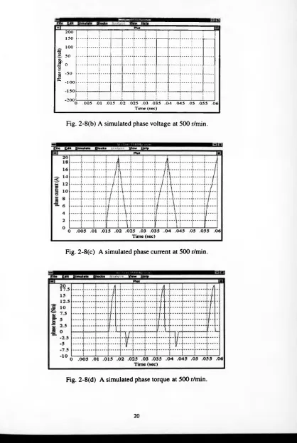
Fig. 2-8(b) A simulated phase voltage at 500 r/min 20
Fig. 2-8(c) A simulated phase current at 500 r/min 20
Fig. 2-8(d) A simulated phase torque at 500 r/min 20
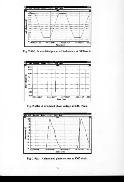
Fig. 2-9(a) A simulated phase self-inductance at 3000 r/min 21
Fig. 2-9(b) A simulated phase voltage at 3000 r/min 21
Fig. 2-9(c) A simulated phase current at 3000 r/min 21
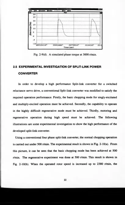
Fig. 2-9(d) A simulated phase torque at 3000 r/min 22
Fig. 2 -10(a) Phase current and voltage waveforms during
mtoring state (2380 r/min) 23
Fig. 2 - 10(b) Phase current and voltage w aveform s d u rin g regenerative state
(from 2380 r/min) 24
Fig. 2-11(a) Phase current and voltage waveforms during motoring state
(2380 r/min) 24
Fig.2-11(b) Phase current and voltage waveforms during regenerative
state (from 2380 r/min) 25
Chapter 3
Fig. 3-1 3-phase dump-resistor converter 27
Fig. 3-2 Asymmetric half-bridge converter 27
Fig. 3-3 C-Dump converter with resonant energy recovery. 29
Fig.3-4 C-Dump converter with damped energy recovery 30
Fig. 3-5 C-Dump converter with chopping energy recovery 31
Fig. 3-6(a) A 3-phase Miller’s Converter 31
Fig. 3-6(b) A 4-phase power converter 32
Fig. 3-7 4-phase Pollock’s converter 33
Fig. 3-8 A 4 phase split-link converter for a switched reluctance
motor 34
Fig. 3-9 The Switched Reluctance power converter for each phase
Winding 38
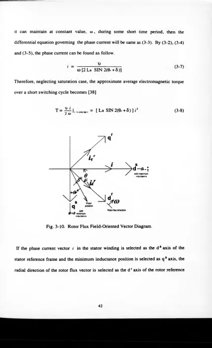
Fig. 3-10 Rotor Flux Field-Oriented Vector Diagram 42
Fig. 3-11 An adaptive synchronous phase current controller block
Diagram 49
Fig. 3-12(a) The periodic pulse phase current response under no load 55
Fig.3-12(c) The periodic pulse phase current response under no load 56
Fig. 3-12(d) The periodic pulse phase current response under no load 57
Fig. 3-12(e) The pulse phase current response during high speed 57
Fig. 3-13(a) Adaptive synchronous phase current and steady state speed
response under periodic load disturbance 58
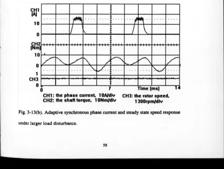
Fig. 3-13(b) Adaptive synchronous phase current and steady state speed
response under larger load disturbance 58
Fig. 3-14(a) Phase current, shaft speed, and shaft torque step response
from zero speed to 730 rpm 59
Fig. 3-14(b) Phase current, shaft speed, and shaft torque step response
from zero peed to 1360 rpm 60
Chapter 4
Fig. 4-1 Split-Link Converter for a 5-phase switched reluctance
motor 65
Fig. 4-2 Relationship between space phase inductance and rotor
Position 65
Table 4-1 Space voltage vectors of a 5 phase switched
Reluctance motor 66
Fig. 4-3 Space voltage vector diagram of a 5-phase switched reluctance
motor 67
Table 4-2a Doubly- excited combinative vectors during forward
rotational state 67
Rotational state) 68
Table 4-3 ( The electrical regenerative vectors which all switches are
turned off) 68
Fig. 4-4 Digital pulse width modulator for the sliding mode power
controller 78
Fig. 4-5(a) Neutral voltage and phase current waveforms under
unbalanced loads, rotor speed 470 r/min 82
Fig. 4-5(b) Neutral voltage and phase current waveforms under
unbalanced loads rotor speed 470 r/min 82
Fig. 4-5(c) Neutral voltage and phase current waveforms under
unbalanced loads 470 r/min 83
Fig. 4-5(d) Phase current, the scalar sum of all instantaneous phase
current, and neutral voltage waveforms under unbalanced loads, rotor
speed 470 r/min 83
Fig. 4-6(a) Steady state response of neutral voltage and phase current
operated without phase advancing at 1230 r/min and high load 84
Fig. 4-6(b) Steady state response waveforms of neutral voltage and phase
operated without phase advancing at 1230 r/min and high load 84
Fig. 4-6(c) Steady state response waveforms of neutral voltage, phase
current, the scalar sum of all instantaneous phase current, and shaft
torque operated without phase advancing at 1230 r/min and high load 85
Fig. 4-7(a) High speed response waveforms of phase current and neutral
voltage using stator flux vector phase shifting approach 85
voltage using stator flux vector phase shifting approach 86
Fig. 4-7(c) High speed response waveforms of phase current, scalar
sum of phase currents and neutral voltage using stator flux vector
phase shifting approach 86
Fig.4-8 Steady state response waveform of the phase current, phase
voltage, rotor speed and shaft torque operated at 1090 r/min 87
Fig. 4-9 The dynamic response of the instantaneous input power, shaft
torque and shaft speed following a sinusoidal modulation of command
input power 87
Fig. 4-10 Speed response of switched reluctance vector drive under
sliding mode speed controller 88
Chapter 5
Fig. 5-1 Block diagram of sliding mode 4 phase switched reluctance
flux vector drive 91
Fig. 5-2 4 phase split-link converter for a switched reluctance motor 93
Table 5-1 Space voltage vectors of a 4 phase switched luctance motor 93
Table 5-2a Doubly-excited combinative vectors during forward
rotation 94
Table 5-2b Doubly-excited combinative vectors during reverse
rotation 94
Table 5-3 ( The electrical regenerative vectors which all switches are
turned off) 95
[image:13.482.34.468.18.675.2]4-phase switched reluctance motor 97
Fig. 5-3(b) Induced space current vectors and desired average current
vector and decoupled current vectors operated in 9i 97
Fig. 5-4(a) Phase current and phase voltage waveforms during
motoring state 105
Fig. 5-4(b) Phase current and phase voltage waveforms during
motoring state 106
Fig. 5-4(c) Phase current and phase voltage waveforms during
motoring state 106
Fig. 5-4(d) Phase current and phase voltage waveforms during
regenerative state 107
Fig. 5-5(a) Phase current and phase voltage waveforms during
motoring state 107
Fig. 5-5(b) Phase current and phase voltage waveforms during
motoring state 108
Fig. 5-5(c) Phase current and phase voltage waveforms during
motoring state 108
Fig. 5-5(d) Phase current and phase voltage waveforms during
regenerative state 109
Fig. 5-6(a) Current and phase voltage waveforms at 500 r/min 109
Fig. 5-6(b) Current and phase voltage waveforms at 2380 r/min 110
Fig. 5-6 (c) Phase current and phase voltage waveforms during
Chapter 6
Fig. 6-1 The asymmetric half bridge power converter circuit for one
phase of a switched reluctance motor 114
Fig.6-2(a) Available space voltage vectors and operating regions of a
4-phase switched reluctance motor 116
Fig. 6-2(b) Induced space current vectors and desired average current
vector and decoupled current vectors operated in 0i 116
Table 6-1 Combined space voltage vectors for reverse rotation 117
Fig. 6-3(a) Sliding mode speed and total phase power control with
integral compensation 124
Fig.6-3(b) Sliding line and phase plane diagram 124
Fig. 6-4 Digital pulse width modulator for the sliding mode power
controller 128
Fig. 6-5 Robust speed control of a 4 phase switched reluctance vector
drive 130
Fig. 6-6 Steady state response of d.c. link current, phase current,
shaft torque, and rotor speed, (a) is operated at 500 r/min. (b) is
operated at 1550r/min 134
Fig. 6-7 Step speed response of a 4 phase switched reluctance vector
drive under sliding mode speed controller 135
Fig. 6-8(a) Speed response operated under uncertain loads using a
sliding mode speed controller. Command speed is 200 r/min 135
Fig.6- 8(b) Speed response operated under uncertain loads using a
[image:15.481.49.446.41.690.2]Fig. 6-8(c) Speed response operated under uncertain loads (a)
using a sliding mode speed controller. Command speed is
2500r/min 136
Fig.6-8(d) Speed response operated under uncertain loads using a
sliding mode speed controller. Command speed is 1500 r/min 137
Fig. 6-9 Block diagram of sliding mode 4 phase switched reluctance
flux vector drive 143
Fig. 6-10 4 phase split-link converter for a switched reluctance
motor 144
Fig. 6-11(a) Phase current and phase voltage waveforms during
motoring state 145
Fig. 6-11 (b) Phase current and phase voltage waveforms during motoring
state 146
Fig. 6-11 (c) Phase current and phase voltage waveforms during
motoring state 146
Fig. 6-11(d) Phase current and phase voltage waveforms during
regenerative state 147
Fig. 6-12(a) Phase current and phase voltage waveforms during
motoring state 147
Fig. 6 -12(b) Phase current and phase voltage waveforms during
motoring state 148
Fig. 6-12(c) Phase current and phase voltage waveforms during
motoring state 148
regenerative state 149
Fig. 6 -13(a) Current and phase voltage waveforms at 500 r/min 149
Fig. 6 -13(b) Current and phase voltage waveforms at 2380 r/min 150
Fig. 6 -13(c) Phase current and phase voltage waveforms during the
transition from high speed to low speed state 150
Fig. 6-14 Step shaft speed response from start to command speed (2860
r/min) 151
Fig. 6-15 Shaft speed response from reverse rotational state
(2060 r/min) to forward rotational state (2285 r/min) 151
Fig. A l. The self-inductance in the phase-1 winding 166
Fig. A2. The voltage in the phase-1 167
Fig. A3. The current in the phase-1 167
Fig. A4. The electrogmagnetic torque in the phase-1 168
Fig. A5. The self-inductance in the phase-2 winding 168
Fig. A6. The voltage in the phase-2 winding 169
Fig. A7. The current in the phase-2 winding 169
Fig. A8. The electromagnetic torque in the phase-2 winding 170
CHAPTER 1
INTRODUCTION
1.1 INTRODUCTION
For a long time d.c. brush motors were used extensively in areas where variable-speed
industrial applications were required. This motor could be controlled easily by the field
and armature current. In particular, the separately excited d.c. motor has been used
mainly for applications where there was a requirement of fast response and four-
quadrant operation with very high performance. However, d.c. motors have certain
disadvantages, which are due to the existence of the commutator and the brushes. So,
they require periodic maintenance and also cannot be used in explosive or corrosive
environments. To overcome these problems, alternating current asynchronous induction
and permanent magnet synchronous motors, which can have simple and rugged
structure, high reliability and efficiency have replaced dc motors in many variable speed
applications. These brushless motors can be used in highly dangerous environments
without maintenance. However, energy density, inertia, efficiency and cost are the main
criteria for the selection of many variable speed products. The induction motor is the
simplest of the brushless ac motors. It will run without any electronic control when
directly connected to an appropriate d.c. supply. When operated in association with an
inverter with vector control, the induction motor can be controlled with a high degree of
accuracy as a high performance servo drive. The permanent magnet brushless d.c. motor
also requires an inverter or electronic commutator and can offer very high performance.
Unfortunately, its cost is high due to the need for expensive magnetic material in the
candidate suitable for variable speed industrial applications because it has the attributes
to meet the requirements of variable speed applications. The main drawback of the
switched reluctance motor has been acoustic noise and vibration such that it has not
been popularly accepted. These two problems are related to high torque ripple. In
normal operation of a switched reluctance motor it is not uncommon to have periods of
negative torque between blocks of positive torque. This increases vibration and acoustic
noise. Therefore, the main aim of this thesis is to solve this problem and provide an
effective solution, namely, the author will show the possibility that Variable Structure
Space Vector theory can be applied to switched reluctance servo drives. Application of
Variable Structure Control (VSC) theory to the field of control of DC servo motors
(Sabanovic and Vujovic 1984) [1], PM synchronous servo motors (Venkataramanan et
al. 1986, Harashima et. 1986) [3], Slotine 1985 [4] ), (Chen and Yeung, Ito 1991) [5]
has been reported. Many other works, which survey the possibility of application of
VSC theory in high-performance servo drives, have been published in the literature. It is
well known that the characteristics of VSC are insensitivity to the variation of system
parameters and external disturbances. However, how can it be applied to switched
reluctance motors and related drives ? These involve the real spirit of VSC theory and
the understanding of the plant system. In this case, the author creates a novel VSC,
which is suitable for any phase switched reluctance motor and drive, so that the
performance of the drive is very robust and its implementation is very simple. In this
thesis there are a total of seven chapters to sequentially describe the novel drive
including effective control schemes to achieve high-performance and a robust servo
1.2 FORMAT OF THE THESIS
Chapter 1 is an introductory chapter, briefly describing the motivation of VSC theory
applied to switched reluctance drives. After chapter 1, the arrangement of the thesis is as
follows.
In Chapter 2, the characteristics and operating principle of the switched reluctance
motor are described. Basically, the switched reluctance motor is derived from the
synchronous reluctance motor but has typically higher motor efficiency. However,
whilst it is increased the salient pole structure introduces high harmonics in the
electromagnetic torque. Control is necessary to avoid generating negative torque. The
main operating principles of the existing switched reluctance motor are described. How
to obtain an effective improvement are discussed in this chapter.
In Chapter 3, power converters for a switched reluctance motor are described. Some
famous power converters, such as asymmetric half-bridge converter, split DC link
converter, C dump converter, Miller’s converter, and Pollock’s converter are briefly
discussed. This chapter shows that in order to provide simpler and better performance of
the drive, a novel control strategy must be added to the converter to achieve an excellent
vector drive. In the next chapters, chapters 4, 5-phase split-link converter for a switched
reluctance flux vector drive is studied.
Following Chapter 4, in Chapter 5, the variable structure space vector control of 4-
phase split-link converter and the principle of sliding mode total phase power control
are described.
In Chapter 6, which is the most important part in this thesis, a robust speed control
schemes and a variable structure space vector controlled flux vector servo drive with
Finally, in Chapter 7, some conclusions about the author’s research will be summarised.
The author’s main contributions and proposed effective solutions to the variable speed
CHAPTER 2
CHARACTERISTICS AND OPERATING PRINCIPLE
OF THE SWITCHED RELUCTANCE MOTOR
A switched reluctance motor has its history stretching back 166 years to the first
“Electromagnetic Engines”. In the last two decades this new type of electrical drive
has been introduced again. The first commercially available switched reluctance
motor was launched by TASC Drives in 1983. Even though the principle of operation
of switched reluctance motor was established in the 1830’s, it could not be
implemented in practice until recently with to the progress of advanced power
semiconductor devices. The new generation of power converters, based on IGBTs as
power semiconductor switches and a digital application specific integrated circuit
(ASIC) has overcome the reliability problem of the drive. Moreover, the computer
aided design of the motor has made it possible to reduce the noise produced by the
motor. Various applications of switched reluctance drives are under investigation at
the moment. Smaller size switched reluctance motors have found applications in
factory automation, positioning servos and variable speed drives. In medium and
higher sizes, it has found application, such as centrifugal pumps and compressor
drives. With its high efficiency throughout the operating range, simple unipolar
converter, absence of rotor windings, it has considerable potential over the inverter
fed induction motor. Understanding of its basic characteristics and operating
principles is necessary to get the best out of the drive. Some basic operating principles
thesis, more advanced operating methods are described. Firstly the basic structure and
operation of the drive are reviewed.
2-1 THE STRUCTURE OF THE SWITCHED RELUCTANCE MOTOR [9 11]
The switched reluctance motor is a doubly salient motor. Basically, it is a
synchronous motor improved from the synchronous reluctance motor. In order to
optimize efficiency, energy density, magnetic material and cost, the motor is generally
designed using a ‘finite element analysis’ approach though many alternative
techniques have been proposed. Usually the rotor poles and the stator poles are
symmetrical about their centre-line and are equally spaced around the rotor and the
stator, respectively. For a typical four-phase switched reluctance motor, this simple
machine has six rotor poles and eight stator poles. A coil is wound around each stator
pole. The coils on diametrically opposite poles may be connected in series or parallel
to form a phase winding so that when current flows in the winding, one pole acts as
north magnetic pole, the other as a south magnetic pole. The reluctance of the flux
path between two diagonally opposite stator poles varies as a pair of rotor poles
moves in and out of alignment. There are no magnets in the rotor, as shown in Fig. 2-
1. The laminations shown are made of magnetically-soft, low-loss steel. The machine
shown in Fig. 2-1 has four phases 1, 2, 3, and 4 as shown. When any pair of rotor
poles is exactly aligned with the stator poles, that phase is said to be in the aligned
position. If current is flowing in that phase winding, there is no torque at that position
because no Back EMF is produced since there is no variation of incremental
inductance. In this aligned position, the phase inductance is at maximum because the
rotor is aligned with the stator pole of a phase, that position is called the unaligned
position, as shown in Fig. 2-2. In the unaligned position the phase inductance is at its
minimum because the magnetic reluctance of the flux path is at its highest. The low
inductance in this position means that there is rapid current rise during high speed
2-2 ENERGY CONVERSION PRINCIPLE OF THE SWITCHED
RELUCTANCE MOTOR [11-12]
Electromechanical systems are generally composed of an electrical system, a
mechanical system, and a means whereby the electrical and mechanical system can
interact. Both electrostatic and electromagnetic coupling fields may exist
simultaneously. Losses will occur in all of the components of the electromechanical
system. Heat loss will occur in the mechanical system due to friction and the electrical
system will dissipate heat due to the resistance of the current-carrying conductors.
Eddy current and hysteresis losses occur in the ferromagnetic material of all magnetic
fields while dielectric losses occur in all electric materials. If We is the total energy
supplied by the electrical source and Wm the total energy supplied by the mechanical
source, then the energy distribution could be expressed as
We = We + WeL + WeS (2-1)
WM = Wm + WmL+ WmS (2-2)
where We is the energy transferred to the coupling fields by the electrical system. WeL
are the heat losses which are associated with the electrical system and Wes is the
energy stored in the electric or magnetic fields which are not coupled with the
mechanical system. WmL is the energy losses of the mechanical system in the form of
heat, Wms is the energy stored in the moving device of the mechanical system, and
Wm the energy transferred to the coupling field.
If Wf is defined as the total energy transferred to the coupling field, then
W f = Wf+ Wa. (2-3)
where Wr is energy stored in the coupling field and Wn. is the energy dissipated in
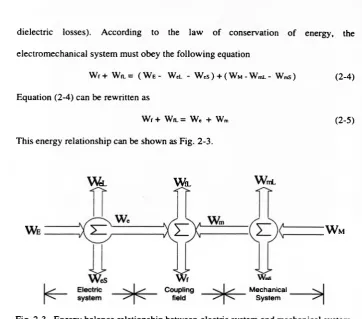
dielectric losses). According to the law of conservation of energy, the
electromechanical system must obey the following equation
W f+ WfL= ( W e- WeL - W e s ) + ( W M-WmL- WmS) (2-4)
Equation (2-4) can be rewritten as
Wf + WfL = W, + Wm (2-5)
This energy relationship can be shown as Fig. 2-3.
W eL W fL
WrrL
W m
Mechanical System
Fig. 2-3. Energy balance relationship between electric system and mechanical system.
If the losses of the coupling field can be neglected, then the field is conservative and
the equation (2-5) becomes
Wr = W* + Wm (2-6)
For a switched reluctance motor, the voltage equation which describes the electrical
system may be expressed as follows
\ = r i + L — + E f (2-7)
d t
where £> is the voltage drop across the coupling field, r is the resistance of motor
[image:26.483.53.416.30.349.2]flowing through motor phase winding. The electromagnetic torque can be expressed
as
dt2 dt (2-8)
where J is the inertia constant, B is the viscous constant, 0 is the rotational
displacement of the rotor, T is electromagnetic torque and Tl is the load torque.
The total energy supplied by the electric source during time dt is
We= \ \ i d t (2-9)
The total energy supplied by the switched reluctance motor is
Wm=
J
TdQ (2-10)which may also be expressed as
Wm= / T ( ^ V (2-11)
Substituting (2-7) into (2-9) yields
We = r j i 2dt + + JE/ i d t (2-12)
The first term on the right-hand side of (2-12) represents the energy loss due to the
resistance of the switched reluctance motor circuit ( W «l). The second term represents
the energy stored in the electromagnetic field external to the coupling field ( Wes). So,
the total energy transferred to the coupling field from the electric system is
W. = j E f i d t (2-13)
Similarly, for the mechanical system
Wm = J f ^ d Q + Bf (— ) dt - f TLdQ (2-14)
The first term on the right-hand side of (2-14) represent the kinetic energy stored in
the inertia of the switched reluctance motor. The second term is the heat loss due to
friction ( WmL). Thus, the total energy transferred to the coupling field from the
mechanical system is
Wm = - J Tz. ¿0 (2-15)
It is important to note that a positive torque Tz. is assumed to be in the same rotational
direction as a positive rotational displacement ¿ 0.
Substituting (2-13) and (2-15) into (2-6), yields
Wz = J Ef id t - J Tl dQ (2-16)
For a switched reluctance motor, Ef is the back EMF, denoting the variation of the
stator flux linkage, i.e. Ef = ^ / ¿ t, where A is the stator flux linkage. Substituting
Ef into (2-16), yields
Wz =
J
idX -Jtz.
dd (2-17)If there is no mechanical rotational displacement, the (2-17) becomes
Wz =
J
i d k (2-18)This coupling field energy corresponds to the area to the left of the A, - i curve shown
in Fig. 2-4, which represents the energy stored in the field at the instant when A =
A. and i = z>. The area to the right of the A - i curve is called the coenergy, which can
be expressed as follows
Fig. 2-4. Stored energy and coenergy in the magnetic field
of the switched reluctance motor.
From Fig. 2-4, it can be seen that the sum of Wf and Wc is X times i, namely.
X i = Wc + Wr (2-20)
Taking the partial derivative with respect to the rotational displacement on the both
side of the equation (2-20), yields
, di d k 3Wc 3Wf
dQ dQ 39 30 (2-21)
From (2-9),(2-10), (2-17), (2-19) and (2-21), the equation (2-22) can be obtained.
aWc _ , di .dX awr
ae de dQ ae (2-22)
The equation (2-22) is the most general expression for the torque produced by the
switched reluctance motor. From this equation, one very important concept can be
obtained, i.e. the electromagnetic torque can be decomposed into two parts: One is
from the variation of the current with respect to the rotational displacement, another is
exactly so-called moving load torque. If there is no variation of the current or rotation,
[image:29.485.35.444.35.678.2]equivalent to the load torque. In this case, the load or external disturbance torque can
be estimated as being equivalent to the electromagnetic torque under sliding mode
current control. This feature will be described fully in chapter 4. It should be noted
that for a net electromagnetic torque to be present in the motor system, there must be
either current variation or the rotational displacement.
2-3 OPERATING METHOD
A. Constant Torque Operation - Chopping Mode
This mode is generally used at low speed, which is necessary to control the flux
linkage or phase current. This mode can be subdivided by three type: ‘open loop
voltage PWM’ and ‘ current regulated PWM’, dependent on controller. Each
operating mode can be subdivided into ‘soft chopping’ and ‘hard chopping’,
dependent on the converter used. For voltage PWM-soft chopping, the asymmetric
half-bridge converter is suitable. Thus one switch can be left on and the other one can
be switched on and off at a high frequency with a fixed duty-cycle over the switching
cycle. As for voltage PWM- hard chopping, it can be carried out in a power converter
with either one switch or two switches per phase. For asymmetric converter, both
switches can be switched together at high frequency. For split-link converter, only one
switch is switching in a similar way. This operating method is generally not suitable
for motoring operation because it will increase the current ripple by a large factor but
it is suitable for regenerating or braking operation to control current. Another
chopping technique: current regulation - soft chopping can be used in the regulation of
as the current is greater or less than a reference current. Usually a hysteresis-type
current regulator is used. Fixed frequency-type current modulation techniques can also
be employed.
B. Control of Voltage conduction angle
This is a popular method suitable for medium and high speed operation but it is not
suitable for low speed and lightly loaded cases. This is because torque pulsation is
obvious during low speed and light load, but since the time period is short at high
speed so that pulsing torque does not cause an obvious mechanical oscillation.
Generally, the turn-off angle is fixed at a point prior to the aligned position to avoid
negative torque and the turn-on angle is adjustable. With larger load, the conduction
angle can be increased by advancing tum-on angle and fixing turn-off angle
appropriately.
C. Constant power operation - Single pulse mode
During high speed operation, the turn-on angle and turn-off angle needs to be
advanced, otherwise there would be substantial negative torque produced in the
switched reluctance motor system at the end of each pulse. This has the effect of
increasing the phase angle of the current with respect to the rotor. To achieve this aim,
field-weakening is necessary. It is preferable to use single pulse excitation in the phase
windings to avoid producing negative torque. Also, by phase advancing, the flux
linkage becomes lower and the induced Back EMF is not higher than the supply
level so that maximum constant power can be obtained. By phase advancing and
employing single pulse operation of the phase current, flux linkage can be weakened
and the speed can be increased rapidly and the motor run at very high speed. The
switched reluctance drive can therefore operate over a very wide speed range with
good power output characteristics.
D. Modulation Of Current Conduction Angle
Another simple control operation is the modulation of total current conduction angle
with turn on and turn off angles with respect to the rotor position by modulation of the
current level. Using the method, the maximum conduction angle can be modulated
according to the PWM voltage level or by current chopping technology.
E. Sliding Mode dc link power control with phase current feedforward
This approach is the author’s invention, and is described later. Since the switched
reluctance drive system is a highly non-linear dynamic system, it is very difficult to
predict and estimate the effects of changes in the system. In this case, conventional
control methods struggle to satisfy the requirement of a real system. Even if a general
closed loop controller is used, the performance is still not acceptable. However, from
the point of view of energy conservation, if the power delivered to the drive system
can be controlled by a good control scheme, then the drive system and its related
performance could be significantly improved. In the later chapters, this principle is
described. By d.c. link power control and a phase current feedforward technique the
electromagnetic torque during sliding mode can be reduced to a very simple equation.
Combined with a variable structure speed controller, the drive system become highly
robust.
2.4 ANALYSIS AND SIMULATION OF SWITCHED RELUCTANCE MOTOR
CHARACTERISTICS
According to equation (2-7), the general voltage equation of a switched reluctance
phase winding can be rewritten as follows:
_ . . . . d i .dL{Q,i) dip . dMQ.i)
v = R i + L(0,i)— + i---1 A/(0,i)---- + ip
---d t d t d t d t (2-23)
where R is the sum of the stator winding and switch resistance, L(0,/') is the phase
inductance, ip is the algebraic sum of the instantaneous phase current in previously
excited phase and the instantaneous current from other phases, A/(0,i) is the mutual
inductance between this phase and another phase, p, 0 is the angular position of the
rotor and (0 is the angular frequency of the rotor. Other parameters are the same as in the equation (2-7). Therefore, the switched reluctance motor can be represented by an
equivalent circuit shown in Fig. 2-5.
.dL(Q,i) dip . dMQ,i)
where e = i ---+ M (0,i)--- U
p---d t d t d t
. dL(Q,i) d ip . dMQ,i).
= [/— ^— - + --- + ip --- ] co
1 d d y , d Q d B (2-24)
From equation (2-24), it can be seen that that e is proportional to to, denoting the
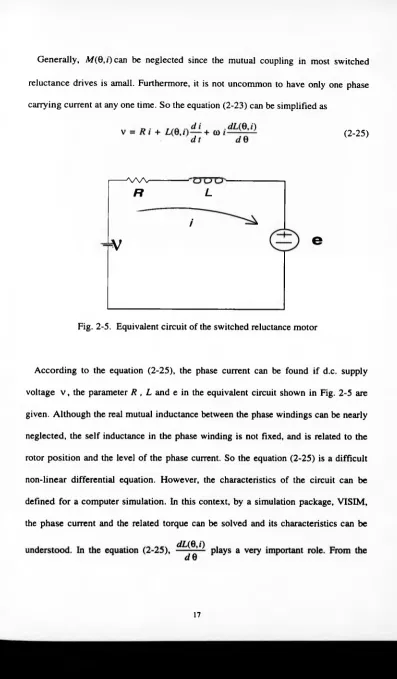
Generally, A/(0,j) can be neglected since the mutual coupling in most switched
reluctance drives is amall. Furthermore, it is not uncommon to have only one phase
carrying current at any one time. So the equation (2-23) can be simplified as
According to the equation (2-25), the phase current can be found if d.c. supply
voltage v , the parameter R , L and e in the equivalent circuit shown in Fig. 2-5 are
given. Although the real mutual inductance between the phase windings can be nearly
neglected, the self inductance in the phase winding is not fixed, and is related to the
rotor position and the level of the phase current. So the equation (2-25) is a difficult
non-linear differential equation. However, the characteristics of the circuit can be
defined for a computer simulation. In this context, by a simulation package, VISIM,
the phase current and the related torque can be solved and its characteristics can be (2-25)
AA/V
L
R
i
tV
e
[image:34.485.43.440.0.679.2]geometry structure of the motor lamination, the self inductance profile can be
conveniently approximated by a sinusoidal function plus a d.c. component. So, for a
8/6 four phase switched reluctance motor, the inductance can be expressed as follows:
L = Lo + Lt sin 60 (2-26)
where Lo is the d.c. component of the self inductance and L\ is the amplitude of the
fundamental component of the self inductance.
Figure 2-6 is the block diagram of the self inductance using VISIM package. In this
diagram, Lo = 0.0375 h and Li= 0.035 h, the angular frequency is 1256.637 Hz the
inductance profile is edited by a modified sinusoidal function. Combined with the
figure 2-6, the equation (2-25) can be implemented by the block diagram shown in
Fig. 2-7. In the Fig. 2-7, the resistance is 4 ohm,and the input d.c. supply is 300 V. It
is assumed that a split d.c. converter is used so that the voltage used for each phase is
150 V. Fig. 2-8 shows the simulated results which the motor is operated at 500 r/min.
Fig. 2-8(a) is the simulated phase inductance in henries. Fig. 2-8(b) shows the
simulated phase voltage (V). Fig. 2-8(c) shoes the simulated phase current (A) and
CL
Fig. 2-8(d) shows the simulated phase torque (Nm). From Fig. 2-8(te), it can be seen
that there is a regenerative tendancy in the phase current. In the simulated phase
torque, there is a negative torque during decreasing inductance region. This result
shows that the phase current must be operated within the increasing inductance region
to produce an effective positive torque and to avoid negative torque. Therefore, the
phase current must be advanced to avoid producing negative when the motor is
operated under high speed. This fact can be seen from the simulated results shown in
Fig. 2-9(a) - Fig. 2-9(d), operation here is at 3000 r/min, whose turn-off phase angle
- J P l o t
200 150
_ 100
~ 3
50 & i s 0
[image:37.481.47.465.30.654.2]o | - 50 ® -1 0 0
-2 0 0
.0 0 5 .01 .0 15 .0 2 .0 25 .03 .0 35 .0 4 .0 4 5 .05 .0 5 5 .0 6 T im e (sec)
Fig. 2-8(b) A simulated phase voltage at 500 r/min.
Fig. 2-8(c) A simulated phase current at 500 r/min.
Fig. 2-9(a) A simulated phase self inductance at 3000 r/min.
2 0 0 150
100 "o e 5 0
O0 ~ 0 0
1 - 50 -1 0 0
-2 0 0 (
» 0 1 0 4 1 6 7 .0 0 4 1 6 6 6 7 .0 0 7 2 9 1 6 7 .0 1 0 4 1 6 7 .0 1 2 T im e (sec)
[image:38.483.41.469.33.662.2]-5
000104167 .00416667 .00729167 .0104167 .012
T i m e (sec")
Fig. 2-9(d). A simulated phase torque at 3000 r/min.
2.5 EXPERIMENTAL INVESTIGATION OF SPLIT-LINK POWER
CONVERTER
In order to develop a high performance Split-link converter for a switched
reluctance servo drive, a conventional Split-link converter was modified to satisfy the
required operation performance. Firstly, the basic chopping mode for singly-excitated
and multiply-excited operation must be achieved. Secondly, the capability to operate
in the highly difficult regenerative mode must be achieved. Thirdly, motoring and
regenerative operation during high speed must be achieved. The following
illustrations are some experimental investigation to show the high performance of the
developed split-link converter.
Using a conventional four phase split-link converter, the normal chopping operation
is carried out under 500 r/min. The experimental result is shown in Fig. 2-10(a). From
this picture, it can be seen that the basic chopping mode has been achieved at 500
r/min. The regenerative experiment was done at 500 r/min. This result is shown in
[image:39.485.28.438.26.695.2]chopping performance disappears but doubly-excitation operation under phase flux
advancing is carried out. This result is shown in Fig. 2-11(a). From this figure, the real
phase current in channel one and channel two can not be chopped at the prescribed
reference level but the corresponding phase voltage waveform in channel three and
four show that the modulation of the phase flux can still be partly achieved. The
corresponding regenerative operation, running around 2380 r/min, was carried out.
The result is shown in Fig. 2-11(b).
Fig. 2-10(a) Phase current and voltage waveforms during motoring state.
Chi: phase-1 current, 10 A/div; Ch3: Phase- voltage, 400 V/div;
Ch2: phase-2 current, 10 A/div; 400 V/div; Ch4: phase-2 voltage, 400 V/div.
T e k Q E J B 10OkS/s 154 Acqs
i--- T---1 --- ,--- |---
I---!---. I---!---. I---!---. I---!---. I---!---. I---!---. -r : • • •:
i :
... + ...
NrWf h** 1|If P* W" * 1w l (Hit ™ IpliWW “ P^fl|PPiTpj|T|
“
ch 1 ~ s : M ir ‘ " e f a " i6smV] ' M s.so m s ch r y • • 2.3 V
Ch3 lo.omv HID i.oov
Fig. 2 -10(b). Phase current and voltage waveforms during regenerative state.
Chi: total som of all phase currents,12.5 A/div; Ch3:phase-1 current, 10 A/div;
Ch2: d.c. link current, 5 A/div; Ch4:shaft speed, 500 r/min.
Time: 2.5 ms/div.
Fig. 2-11(a) Phase current and voltage waveforms during motoring state.
C hi: phase-1 current, 10 A/div; Ch3: Phase-1 voltage, 400 V/div;
Ch2: phase-2 current, 10 A/div; Ch4: phase-2 voltage, 400 V/div.
1.00 v àni to.omv MS.ooms Chl I Î751TV3
2 . 0 0 V C h 4 2 . 0 0 V
Fig. 2-11(b). Phase current and voltage waveforms during regenerative state.
Chi: phase-1 current, 10 A/div; Ch3: Phase-1 voltage, 400 V/div; 10 A/div;
Ch2:phase-2 current, 10 A/div; Ch4: phase-2 voltage, 400 V/div.
Time: 5 ms/div.
These tests show that the basic operation of the converter has been proven. The
author will now go on to develop the advanced control algorithms that lead to
CHAPTER 3
POWER CONVERTER AND SWITCHED
RELUCTANCE DRIVE
3-1. Introduction
There are several well known power converters which be used in a practical switched
reluctance drives such as the Dump-Resistor converter, the asymmetric half bridge
converter, the C-Dump, Miller, Pollock, and split-link converter. In this chapter,
several frequently used power converters are described. In addition, a simple and
effective control scheme is added to a power converter to achieve synchronously
singly-excited, switched reluctance drive. As for more advanced power converter for a
switched reluctance flux vector drive is described, in detail, in the next chapter and
chapter five.
3-2. Existing Power Converter [12-24]
A. Dump-Resistor Converter
The circuit is shown in Fig. 3.1 for a three-phase switched reluctance motor. Only a
snubber circuit and one dump resistor are necessary. Only one power supply is
required for all the gate drive circuits because all the switches share a common point.
When a phase switch is turned on, a dc-link voltage is applied to the phase winding.
Energy is transferred from dc-link source to the motor. Part of energy is converted to
turned off, the stored energy freewheels via the winding, the freewheeling diode, and
the dump resistor so that part of the energy is dissipated in the dump resistor and
winding resistance while the rest is converted into mechanical energy. During this
operating period, the voltage across the switch equals the sum of the voltage drop
across the dump resistor and dc-link supply. This advantage of the circuit is simple in
its converter topology but its disadvantage is the high energy losses in the Dump-
resistor if high frequency switching is required under high load.
Lf
Fig. 3-1. 3-phase dump-resistor converter.
B. Asymmetric half-bridge converter
Fig. 3-2. Asymmetric half-bridge converter
This circuit uses two power semiconductor switches and two fast recovery diodes
conventional modes of operation which can be used. The first one is the positive
voltage loop, which occurs when both power switches are simultaneously turned on.
In this state, the supply voltage is connected across the related phase winding and the
current in the phase winding is produced. The second operation is called ‘zero voltage
loop’, which occurs if either of two power switches is turned off when current is
flowing in the phase winding. In this case the phase current continues to flow through
the power switch and the corresponding freewheel diode. During this operating state,
the Back EMF induced in that phase winding becomes the power source and the
current flowing in this loop gradually decreases due to the power dissipation in the
phase winding resistance. The third operating state is called ‘negative voltage loop’,
which occurs when both power switches are simultaneously turned off. In this case,
the current is forced flow through both freewheel diodes and the dc power supply
loop. The current decreases rapidly because the energy stored in the motor is returned
to dc supply. Selected power switches and freewheel diodes must be sufficiently rated
to withstand the transient votage and currents. The main disadvantages of the circuit is
that it requires two power switches and two freewheel diodes per phase. Too many
power switches and diodes will increase the switching losses during switching state.
So, this circuit is not suitable for high frequency switching operation. However, its
main advantages are :
(1) The rated positive dc power supply voltage can be used to increase the phase
current during positive voltage loop so that the current level can reach the required
(2) The rated negative dc power supply voltage can be used to decrease the phase
current during a negative voltage loop to return excessive energy from the motor to dc
power source.
(3) The phase current can usually be maintained at the required level by zero voltage
loop when chopping mode is necessary.
C. C-Dump converter
a. C-Dump converter with resonant energy recovery
Referring to the circuit shown in Fig. 3-3, the circuit is called ‘the C-dump converter’
because the trapped energy is dumped into a capacitor before being returned to the dc
supply by a resonant circuit. In this circuit, there is only one switch per phase, and it
uses a single rail dc supply. When Si switches off, the phase current ii which was
flowing through Si commutates to Dir and begins to charge capacitor C i. As the
voltage in the capacitor is increased, the phase current decreases rapidly. Eventually,
all the trapped energy is stored on the capacitor. If energy is required to return to the
dc source capacitor C. S* turns off when u reaches zero. However, during the
resonant recovery, the freewheeling SCR’s become forward biased when Vci = V* .
b. C-Dump converter with damped energy recovery
Fig.3-4. C-Dump converter with damped energy recovery
In Fig. 3-3 the difficulties of the circuit is that Vci falls, well below V*, making it
necessary to use the free-wheeling thristor rather than a free-wheel diode. It is
desirable to maintain the capacitor voltage Vci above the supply voltage. This can be
achieved by the circuit shown in Fig. 3-4. The resistor prevents Vci from dipping
below Vdc, but the resistor also dissipates part of the energy being recovered.
c. C-Dump converter with chopping energy recovery
The circuit in Fig. 3-4 can recover part of the trapped energy while still permanently
maintaining the dump capacitor voltage above the supply voltage. However, the
amount of energy lost during the recovery cycle would be unacceptable. Another
improved topology is shown in Fig. 3-5., which provides a low-loss means of
recovering the stored energy while permanently maintaining the capacitor above the
discharge. After the chopper switch is opened, the stored energy in L is returned to the
source through the free-wheeling diode D.
D. Miller Converter
Although the asymmetric half-bridge converter is a good power converter, allowing
three types of operating modes, it is unsuitable for multiple phase motors because it
needs many switches and freewheel diodes. Therefore, an improved design was
developed by Miller [12]. The circuit shown in Fig. 3-6(a) is its typical circuit for
three-phase switched reluctance motors. The upper transistor S serves all three phases,
while the lower switches control each phase. S must be operated with a sufficiently
A useful variant uses one upper switch between each pair o f phases in a 4-phase drive,
giving a total of six transistors, as shown in Fig. 3-6(b). If the chopping transistors are
connected to phase 1 & 3 and 2 & 4 respectively, the problem of overlap is greatly
reduced and all phases can have the maximum reverse voltage during turn-off.
However, the improved circuits are suitable for only single excitation. According to
author’s research, Miller’s converters are not appropriate for simultaneous, multiple
excitation because the shared top switch will be burned down during high speed or
regenerative state unless a very high current rating switch is used.
E. P o llo c k C o n v e rte r [19]
This circuit for a four-phase is shown in Fig. 3-7. It contains two power switches,
Sh and Sd , each one connecting two of the phase windings to the positive supply rail,
and two further switches, S« and Sc, to connect the other ends of the phase windings
to the lower supply rail. Each phase winding is connected to a different pair of top and
bottom switches. This circuit has the switch to motor voltage ratio of the asymmetric
half-bridge and yet has only one switch per phase winding. The current rating of each
In this circuit, each switch is connected to two phase windings. The flow of current
in both the phase windings is affected if the state of the switch is changed. Namely, a
positive voltage loop in one phase winding cannot be accomplished by a negative
voltage loop in the adjacent phase winding. Sequentially excited phase windings share
a common switch. When the current is flowing in phase winding 1. Switch Si> can be
kept on all the time, while switch 5« can be chopped at high frequency with an
adjustable duty ratio or it can be chopped by current feedback. Phase winding 2 is next
to be energized to continue the rotation of the rotor in an anticlockwise direction. By
closing switch Sc the current can build up in phase winding 2. When this current
reaches the required value it can be chopped using switch Sc independently of the
current in the first phase. Some time later it is necessary to decrease the current in
phase winding 1, while maintaining the current level in second phase winding. This
can be achieved by turning off switch S« and interchanging the operation of Sb and
When Sh is on, the current in phase winding 1 decays slowly in a zero voltage loop,
and when it is off, this current falls much faster in a negative voltage loop. The
switching sequence is identical for other switches.
F. Split-link converter [ 12], [ 19]
This converter is a very simple and popular power converter, and is as shown in Fig.
3-8. Its advantages are that it has the minimum number of power switches and energy
can be returned to the power source during tum-off period. The DC link voltage is
split with two capacitors so that only half o f the full voltage from the input source can
be used. Therefore, the converter is usually suitable for only low speed operation
because the phase current cannot be chopped during high speed and the half of the full
voltage limits the maximum back EMF induced in the phase winding so that the
highest rotor speed is limited. Another disadvantage in the converter is that it cannot
be used in odd-phase motors because an unbalanced phase voltage across each phase
winding will occur.
3-3 Space vector controlled split-link converters
This converter developed by the author is basically a split-link converter but its
performance is absolutely different from the conventional one. It retains the
advantage of traditional split-link converters but it can also be used with odd-phase
motors. This is one of author’s significant contributions to switched reluctance power
converters. Used in odd-phase switched reluctance motors, the unbalanced supply
voltage problem can be overcome even under high load conditions because a
feedforward current controller or a phase power controller can be used to solve this
problem. In chapter four and five, space voltage vectors will be suitably selected to
regulate flux linkage by a variable structure controller with sliding mode. Thus the
proposed split-link converter can not only be used in low speed operation but also in
high speed operation. Under multiply-excited operation or even in regenerative mode,
3-4. SYCHRONOUS S1NGLY-EXCIED POWER CONVERTER
The switched reluctance motor is a doubly salient machine, which has a nonuniform
air gap between the stator and the rotor, giving a nonlinear variation in inductance of
the stator winding as the rotor rotates. The higher the speed is, the quicker the variation
of the inductance becomes, making a rapid dynamic nonlinear time-varying system. In
this situation, the torque developed by the switched reluctance motor is determined by
the angular position and the amplitude of the phase current [25]-[30]. Conventionally,
the phase current controller for the switched reluctance motor has been designed only
considering the current control, ignoring the requirement of the load. Such a current
controller may not be particularily good when load disturbances exist in the real drive
system [25]-[30], The most obvious problem is that the current waveform is distorted
during load variation even if it is under light load. Another example is that the drive
system can easily oscillate because of variation of the mechanical load. Owing to the
shortage of load regulation, a drive using a conventional current chopper can easily
oscillate at the mechanical natural frequency even when closed loop speed control is
added. In this section, the author propose a simple synchronous singly-excited phase
current controller for a switched reluctance drive. The current controller is different
from the conventional current chopper because it can regulate load angle such that the
relative electric angle between the phase current and rotor pole is located between rt/8
and 3it/8. When the relative angle is located between n/8 and 3n/8, the current
controller will become a current chopper under the normal motoring operation.
a.c. machine becomes unnecessary and the simple split-link power converter can be
used to achieve high-performance switched reluctance drive..
3. 4-1 BASIC ANALYTICAL MODEL AND CONTROL PRINCIPLE
A. Control Characteristics of Singly-excited Switched Reluctance Drives
The general voltage equation for each phase winding in the conventional power
converter circuit of the switched reluctance motor, as shown in Fig. 3-10 , is given by
where v> is the voltage applied to the phase winding and r is the resistance, i the
current , and X the stator flux linkage associate with the switched reluctance motor
phase coil, respectively. The flux linkage equation can be expressed as
where z/e,0 is the instantaneous inductance of phase windings, through which phase
current / is flowing, at angular position Or. By neglecting the voltage drop on the
resistance and substituting (3-2) into (3-1), we get
dt (3-1)
x = ue, i) i (3-2)
(3-3)
Fig. 3-9. The Switched Reluctance power converter for each phase winding.
Equation (3-3) shows that the phase current is dependent on the phase voltage, L(Q,i)
and d Z/e, i)/d6, but the solution of equation (3-3) to find the current is very difficult
because Z/0,i) and dL(Q,i)/dQ are nonlinear functions of the position 0r and current
i . To simplify the control of phase current, it is appropriate to control di/dt. If over a
switching cycle the change in current, A i, can be controlled to be small, then di/dt
can be approximately to zero. Therefore, equation (3-3) becomes
(3-4)
From (3-4), it can be seen that the phase current i depends on to . If the shaft speed,
to , is high such that back EMF, to dL(Q,i)/d& , is sometime larger than power supply
voltage Vdc, then phase current i will decrease. Thus the phase current waveform
will be distorted or will become uncontrollable in this situation. Therefore, phase
current must be limited to a maximum value at rated speed. Assume this value is