MODULAR PALLET
DESIGN
INTERNSHIP REPORT
Amit Desai (s1878476)
MSc Mechanical Engineering (DPM)
(29-Jan-2018 to 26-Apr-2018)
Wouter Witzel Euro Valve B.V.
Industrieterrein De Pol 12
7581 CZ Losser, The Netherlands
Supervisor
Bas Dierselhuis
Tooling & Work Preparation Manager, Work preparation
[email protected]
University of Twente
PO Box 217
7500 AE Enschede
The Netherlands
Academic supervisor
1
Acknowledgements
This design report is the result of internship performed at Wouter Witzel B.V. on a design assignment. This report gives an overview of designing a Modular Pallet which is a part of a RECap (Automation project) at the company.
I would like to thank dr.ir. T.H.J. Vaneker (Tom), for recommending me this Topic. I would like to sincerely thank Mr. Bas Dierselhuis & Mr. Gydo Nijensteen for considering me eligible for working on the assignment and also for continuous guidance & assistance.
I would also like to thank all the other colleagues who assisted and helped me throughout the entire design, development and testing phases.
I hope my solution could be developed well to aid with the automation process and help in effective performance of the entire system.
I have gained a lot of knowledge and I hope to implement the same in future. Amit Desai
Abstract
RECap stands for Robotic Experience Centre als proeftuin. ESPS (Almelo) initiated this project. University of Twente is one of the project participants. The main purpose of this project is Efficiency & quality improvement, to reduce absenteeism, Lead time reduction and to stay competitive with low-wage countries.
At Wouter Witzel (WW) there is a huge variety in type and size of valves which are manufactured/assembled. For the project only EV butterfly valves DN40 to DN350 (based on the size) have been considered. More detail on the variation is provided further ahead in the report.
A modular pallet had to design that could have been either separate pallet module that could be placed inside a standard euro pallet or it could be a completely new pallet which could be used on the automated line. It was to be designed only for bodies and discs. Initial phase of the assignment was studying the different types of products (valves) and determining the necessary parameters to be taken in consideration for the final design. Based on the study a detailed document comprising of all the dimensions of the body and disc was prepared.
With the reference to this document further analysis was performed to determine the orientation of bodies and discs. After checking for different orientation possibilities it was decided to place the bodies resting on the bottom hole and the disc on bulged projections which accommodated the shaft holes. The next phase was to design a structure which could be used to place the bodies and discs in desired orientation. A detailed requirement list was defined to initiate and guide the process. With the requirements being clear several solutions were proposed and evaluated. Results of evaluation was to place the bodies on a centring pin which would be used to support it on the bottom hole and for the discs a fixture was proposed. Both the pins and fixtures were designed to be modular and compatible with the variation in sizes and types. After a design, development and prototype testing a final design was proposed for both the components. The modular pallet was to be made in accordance with the dimensions of the EUR pallet. Different material and production process were studied. After evaluating these based-on production numbers, feasibility, cost and maintenance a decision was made to make the pallet module plate from wood and fix the pins & fixtures on it.
The next step in the process was to determine the number of bodies and discs that could be placed in a single pallet. Based on the sheet prepared in the initial stage a critical analysis was performed to check the position at which the bodies must be placed. And the positioning of the discs fixture was checked to have an equal quantity of bodies and discs. The analysis was performed for all the different type and sizes. Based on the check different combination of sizes was checked and evaluated to determine the final design.
The validation of the pins and orientation was done by doing a vision check of the bodies
3
1
Contents
2 Background Information ... 4
Wouter Witzel Euro Valve BV ... 4
Problem Definition ... 4
Automated Assembly Process ... 5
3 Research & Analysis-I ... 6
Modular Pallet: ... 6
Positioning of the Body: ... 6
3.2.1 Governing Parameters ... 6
Gripper for the Body: ... 10
Gripper for the Disc: ... 11
Placement of the bodies ... 12
4 Analysis-II ... 14
Design of Disc fixture: ... 20
Quantitative Analysis ... 23
5 Holding the Bodies in position; ... 27
6 Testing and Validation ... 30
Prototype Test-I ... 30
6.1.1 Modular Pin Test ... 30
6.1.2 Modular Disc Fixture Test ... 31
7 Summary & Current State ... 34
8 Conclusion ... 34
9 Technical Drawings ... 35
10 References ... 46
11 Appendix ... 47
A. Detailed dimensions of the bodies ... 47
B. Detailed dimensions of the discs ... 48
C. Position analysis for DN200-DN350 ... 49
D. Pallet Combination for different sized bodies ... 50
E. Disc fixture concept grading ... 51
F. DN150-DN350 Disc Fixture Position check... 51
2
Background Information
Wouter Witzel Euro Valve BV
Since 1966, the Dutch company Wouter Witzel has been an international leader in the field of butterfly valve manufacturing. It develops and produces a wide range of high quality industrial butterfly valves and accessories. The products are used in pipelines as shut-off valves, control valves and non-return valves. They provide full range of manual control devices, actuators and accessories for specific conditions. The Wouter Witzel products meet the most stringent international quality requirements and are extremely durable. The products are mainly supplied to customers in seven markets:
• 1. Water Treatment • 2. Ship Building • 3. Oil & gas • 4. Desalination • 5. Building Services • 6. Power stations • 7. District Cooling
The company is located in Losser, Industrieterrein De Pol 12 and the major operation at this plant is manufacturing and assembly of the valves along with research and development of new products. Raw materials and some finished components are supplied by external manufacturers.
In general, 11 components (Figure: 1) are required to make the final product assembly, this does not include the actuation mechanism. The Mechanism could be different as per size and type and may change as per the customer demand.
Figure 1: Butterfly valve components.
At present the workforce manually assembles the valves. And the company has decided to automate this process. Under this automation process, apparently a limited size and type of valves are considered. As per earlier design of disc and drive shaft, they were kept firmly assembled in the warehouse. As per the new design the end of drive shaft which goes in the discs had hexagonal cross section. The disc design is being modified as per the design of the shaft. Therefore, all parts will be kept separate at prescribed location.
Problem Definition
5
only reduce the Takt Time but would also increase the production. Thus, it would be an effective step to beat the competition in the market.
In the automation process, my part of work was to design a modular pallet which could be used in coordination with the robotic system to pick and place the components from the pallet onto the product carrier. The pallet must be able to accommodate different sizes of products under consideration. Analysis has to be made on:
1. Can a single pallet be used for all the sizes? If not, how many types of pallets would be needed? 2. Is there a possibility of combining the sizes?
3. How should the components be placed? 4. What type of fixture would be needed? 5. How to manufacture the proposed design?
6. What type of vision system to be used for locating parts in the pallet? 7. What type and how many grippers should be used?
Automated Assembly Process
The whole assembly of the valve would be purely done by robotic system on a specially designed platform. The platform would be a part of a conveyor system with a product carrier mounted on it. The Product Carrier is designed to accommodate different size valves, and every carrier would be carrying all the components of a particular size as per the order to the assembling unit. Apparently, on the product carrier all the components except for disc and body would be placed by an operator present at the start of the line. After this the body and disc are to be placed by a robotic system.
1. Body and Discs are placed by the operator in the modular pallet as per the order.
2. Pallet is carried from the warehouse to the automated assembly line where it is placed in buffer. 4. The pallet is moved from the buffer to a robotic system which checks the type of bodies and disc
with a vision system.
5. Meanwhile, the product carrier (carrying other components placed by an operator at the start of the line, as per the order) moves to the station where the robot places the body and the disc. 6. The robot places the body and the disc on the product carrier.
7. The product carrier then moves to the next station where the assembly is carried out.
3
Research & Analysis-I
Modular Pallet:
Presently, different type and different sizes of valves are manufactured. For the RECap, the company has decided to automate the assembly of limited sized valves. There are 9 different type and 11 different sizes of valves under consideration:
Table 1: Type and sizes of valves.
Type Variants
Size Variants
1.EVS
1.DN40
2.EVCS
2.DN50
3.EVBS
3.DN65
4.EVBLS
4.DN80
5.EVTLS
5.DN100
6.EVTLLS
6.DN125
7.EVML
7.DN150
8.EVFS
8.DN200
9.EVFL
9.DN250
10.DN300
11.DN350
The number following the DN is the inner diameter (in mm) of the valves body and all the other dimensions could vary as per the type of the valve.
The modular pallet is to be designed in a manner to accommodate all the different sizes and types. There are wide variety of bodies under study and hence a detailed analysis of dimensions was necessary. A detailed study of all the dimensions of the bodies and discs was performed with reference to the part drawings available in the system. Based on the study, a detailed document comprising of all the important dimensions was made. And a summery was made addressing the maximum and minimum value which was later used as a guide to come up with ideas for positioning and orientation. (Figure 3). The analysed sheet could be found in Appendix. A.
Positioning of the Body:
An important question to be answered was- How to orient the bodies and discs in the pallet? The orientation was the most important issue that had to be addressed. The orientation was the deciding factor for determining the picking of the components. As per current conditions the bodies are kept horizontal resting on the flat face in the pallet. Hence, to determine the orientation following points had to be considered:
Positioning possibility
Ease of placement by the operator Ease of Detection by the vision system. No hindrance or obstruction by the gripper.
Effectively utilize the pallet space to accommodate maximum bodies and disc. Ease of picking for the robot.
Isolation of the bodies to ensure no damage while transporting. Least movement of the bodies while being transported (stability).
3.2.1
Governing Parameters
Face to face thickness (43-290mm) Diameter of the bodies (104-520mm) Total height (171-552mm)
Weight (2.4-82kg)
7
Figure 2: Dimensions of the Body
Figure 3: Summary of variation in dimensions.
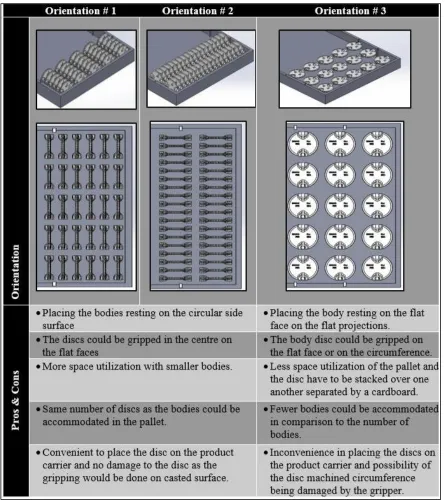
Figure 4: Orientation analysis of bodies
9
Figure 5: Orientation analysis of discs
Comparing the three options of disc orientation, option 1 & 2 are clearly more promising. Both the options are quite similar, there is one major difference that needs consideration. With the 1st orientation option the no. of disc that could be accommodated is less as compared to option 2. Hence, option 2 is more suitable for the purpose.
into the type of gripper that could be used and then design fingers for the gripper to optimize space needed and no. of bodies that could be placed. For the purpose a set of requirements were listed, stated ahead.
Gripper for the Body:
Fingers: 2 or 3. Weight to be carried by the gripper: 2.5Kg- 82Kg (Approximately). Considering factor of safety, it should be able to handle a weight as high as 100kg or lock the body so it can’t slip out. Minimum stroke length per finger 40mm (Preferably 45mm).
Dynamic Moment about the X & Y axis of the gripper 200Nm to 300Nm
The Robot to be used (tentatively) for the pick and place operation has a payload of 180-210 kg. Hence, the Gripper weight along with the weight of the heaviest body should be within the payload limit of the robot.
The top flange of the body is not machined and thus has some casting tolerances, hence there is a possibility of the top flange not being an accurate circular shape because of casting limitations. Therefore, gripper fingers should be able to deal with such unevenness of profile.
If possible, the finger should operate independently.
There is a possibility that the bodies in the pallet are not perfectly oriented. I.e. the body could be inclined or rotated about its axis. Hence, the gripper should be able to centre the body before picking it.
Some bodies have Ribs along the neck and are present at 180° (2 ribs) or 90° (4 ribs). And gripper finger should be able to grip the body by avoiding these structures.
Figure 6: Ribs in some bodies
11
Figure 8: Gripper orientation & stroke requirement
Gripper for the Disc:
Fingers: 2 Weight to be handled: 0.2kg- 15kg (approximately).
Stroke length per finger: 0-40mm (from the tip of the finger).
Gripping force should be sufficient enough to hold the discs in position.
Same gripper is to be used for different sizes, and hence it should be designed in a manner that it could grip the discs of all sizes.
Some discs are convex in shape and hence the gripping surface is uneven. The Gripper should be able to grip such bodies.
The disc should not slip between fingers and the body should not tilt about its transverse axis. Disc must always be gripped at the centre based on its position.
After looking at various grippers available in the market which could be used to meet the operational requirements, a tentative choice of most favourable gripper was made. Schunk PZN-plus 380-2[III] (for the bodies)and Schunk JGp-300-1-IS [IV](for the discs).
Next step was to design the fingers which would give an overview of dimensions of the fingers. This was important because the finger length and thickness would directly affect the placement of the bodies and the discs.
Figure 11: Body gripper Figure 12: Disc gripper
Placement of the bodies
Now that the orientation of bodies and discs was clear and also the preliminary grippers were chosen, it was time to look at the different possibilities of attainting the proposed orientation. The most crucial aspect of the assignment was to make the pallet modular, and hence the fixtures that would be used had to be modular.
To come up with different concepts the dimensional parameter (Appendix. A) was referred.
As per the chosen orientation the bottom side of the body is close to pallet and the dimensions from the bottom side of the body had to be analysed. There were three possibilities of positing the body.
1. A fixture must be made which could hold the body against the outer diameter of the body. 2. A fixture which could hold the bodies by clamping the flat faces of the body which are coated
with rubber.
3. A fixture which could hold the body inside the bottom hole.
After looking at the dimensions of the bodies under study it was quite clear that the first two options of making a fixture to hold the body seem illogical. The major reason was the huge variation in the dimensions, and this variation no way aids in attaining the goal of making the fixture modular. Whereas, the bottom hole has 4 different dimensions over the 11 sizes of bodies and is same for all the types. Hence, the best option is to place the bodies over a robust fixture that could hold the bodies inside the hole.
On the basis of the bottom hole diameter the bodies were sub divided in 4 categories (Table 1). Table 2: Sub-group of sizes
Category
Bottom Hole
Diameter Sizes
1 14 DN40-DN80
2 18 DN100-DN125
3 25 DN150-DN200
4 34 DN250-DN350
For designing the fixture for bodies, following requirements had to be taken in consideration
Robust fixture to carry the weight of the body
It shouldn’t damage the bodies
It should require minimum effort for the warehouse operator to place the bodies on it.
Manufacturing feasibility should be taken into consideration
It should be durable and must withstand the regular usage conditions.
Easy to assemble & disassemble or replace.
13
It should be light weight, because the overall weight of the pallet should not prevent easy handling.
Easy to store and shouldn’t require any special storage condition.
The Body should remain in desired position, i.e. it should not translate or rotate about its position.
As bodies would be carried in the pallet by a forklift, the transportation and driving conditions had to be taken in consideration.
The above stated requirements were checked and a fixture in a shape of a pin was chosen. The pin would hold the body inside the bottom hole and have enough space to rest the bodies. Based on this idea, an initial design of pin was made. Figure 13: Steel pin with changeable casing shows the 1st concept of the pin.
Figure 13: Steel pin with changeable casing
The pin design had two components, male part (inner steel pin) and outer casing (made from plastic). This design met the requirement of making the pin modular. The inner steel pin was made in accordance to the dimensions of the bottom hole of smallest body and the outer casing diameter varied as per the 4 different diameters. The inner pin had an option of thread which would negate the possibility of the casing getting stuck inside the bottom hole. The pin was modular as the outer casing was the only component which had to be changed. The inner pin could be made in bulk and the casing could be fastened. The design had two major drawbacks,
1. The inner pin had to be machined which needed two different operation (Turning & threading). Also, the outer casing was made from plastic and needed a completely different manufacturing process. This would increase the costs of the pin.
2. Every time a different sized body had to be placed the operator would have to replace the outer casing. This would be a problem if the order quantity is high. Moreover, the casing needed a storage space within the pallet, which was not acceptable.
4
Analysis-II
Next phase was to determine the number of bodies and discs that could be placed in the pallet. Based on the brief summary of dimensions and tentative dimensions of the gripper fingers a positioning analysis was performed. The key points addressed during the positioning analysis were:
The Bodies and disc should be placed at a distance in a manner to avoid interference.
In case the orientation of the bodies changes because of the transportation conditions, it should not touch the neighbouring body.
The distance between bodies in immediate vicinity should be enough for the gripper fingers to make the open and close stroke.
There should be enough clearance between the bodies and the walls of the pallet to ensure ease of mounting.
The pallet space should be effectively utilized to ensure placement of maximum amount of bodies.
To determine the exact distance between two bodies and the distance from the pallet walls some specific dimensions had to be considered. The driving parameters were:
The top flange diameter.
Face to face thickness of the machined body.
Outer diameter of the body which also included the projections & ribs.
The modular pallet is to be placed inside the Standard Euro Pallet (Figure 14)
Figure 14: Euro pallet Dimensions
The distance from the centre of the body and disc to the walls of the pallet was determined; for some bodies the flange diameter was bigger than the face to face thickness and had to be checked for. The dimensions are denoted as:
O
d=
Outside diameter with rib/flange projectionD
f=
Top Flange DiameterF
t=
Face to face thicknessD
1=
Distance along the length of the palletD
2=
Distance along the width of the palletC
1=
Distance along the width of the palletC
1‘=
Distance of alternate position along the width of the palletC
2=
Distance along the length of the palletC
2‘=
Distance of alternate position along the length of the pallet 30 & 50mm = Gripper Finger width in open position15
Figure 15: Parameters to determine placement of bodies.
Distance from the boundaries of the pallet
D1= Od
2 + 30, if ( Od
2) > ( Df
2 + 50) [1]
= Df
2 + 50, if ( Od
2) < ( Df
2 + 50) [2]
D2 = Df
2 + 50, if ( Df
2) > ( Ft
2) [3]
= Ft
2 + 20, if ( Df
2) < ( Ft
2) [4]
Distance between two adjacent bodies
C2= Max(Df of the subgroup of flange diameter + 20), if (Od) > (Df) [5]
= (Od+ 50), if (Od) < (Df) [6]
C`2=C2
2 [7]
C1= 2 ∗ Df+ 20, if (Df) > (Ft)and (C22) > (Od) [8]
= 2 ∗ Df, if (Df) < (Ft) or (C22) < (Od) [9]
C`1=C1
2 [10]
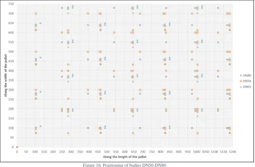
Figure 16: Positioning of bodies DN50-DN80
17
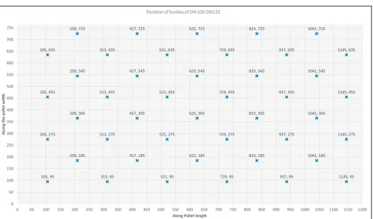
Figure 18: Position of all types of DN125
From the Figure 16 it could be seen that the position of bodies of different sizes i.e. DN50, 65 & 80 are different. Moreover, Figure 17 & 18 show if only one size (DN80 & DN125) is considered, then the point at which the bodies could be placed are different for different type (EVFS, EVFL, EVS, Etc.) of bodies. The case is similar for all the types and sizes. Therefore, the bodies cannot be placed on the determined points because one type of body would certainly interfere with the other body.
Another observation made from the graphs was that the types EVS, EVCS, EVBS, EVBLS had the same position, where as it varied for EVML, EVTLS, EVTLLS, EVFS & EVFL.
Figure 19: Position of bodies for DN40-DN80
Figure 20: Position of bodies DN125
From the graphs:
•Starting point for DN40-DN80- “105, 95” •Starting point for DN 100-DN125- “105, 95”
19
Figure 21: Position of bodies DN40-DN125
Similarly Positioning of the sizes of other sub groups was determined and the combined position of the sub-groups DN150-DN200 & DN150-350. (Figure 21 ).
Figure 23: Single pallet for all types &sizes
It is clear from Figure 23 that if it is opted to place all the bodies in a single pallet at different positions then it would cause interference and there is minimum scope of combining the position. Hence, it is concluded that two different pallets would be need and the 4 sub-groups have been further divided in 2 sub-groups. 1st one comprising of all the sizes from DN40-DN125 and 2nd sub-group covers sizes from DN150-DN350.
Design of Disc fixture:
At the point we had a conceptual design for the pins and the position of bodies but no idea of how the disc should be placed in the described orientation. The earlier 4 sub-groups were further reduced to 2-subgroups, it was clear that two type of disc fixtures were needed.
Governing Parameters
Face to face thickness (L)
Diameter(Dϕ) (40.3-343mm)
Distance at the centre (Tc) (35.3-343mm)
Gripping Position & feasibility
Centre of gravity
21
Figure 24: Disc Nomenclature
Required characteristics of the fixture:
Robust design to withstand rough usage.
It shouldn’t cause any damage to the disc.
It should centre the discs in transverse & longitudinal direction. This is important for pick and placement accuracy.
Light weight to keep the overall weight of the pallet low (ease of handling).
Compatible with different sizes, i.e. modular.
It shouldn’t take too much space as storage could be an issue.
Table 3: Concepts for Disc fixture
Concept 1: Block fixture for the discs. Axially all the discs are in the same plane. Separate slot for disc of
different DN size along the length of the fixture.
Concept 2: Spring loaded support structures to hold the disc in place. Different sized discs could be simply slid in the fixture and the paddings would slide as per
the profile of the disc.
Concept 3: Circular fixture with slots cut out at an
angle. Different slot for different sized discs. different size discs. Each step is in accordance with Concept 4: Stepped disc fixture to accommodate the size and shape of different DN sizes.
All the concepts were carefully checked and evaluated for their pros and cons by the group members (Evaluation Matrix in Appendix. E). The concepts were graded in accordance with the fulfilment of the requirements. Based on the grading and evaluation concept 4 has turned out to be most
appropriate.
Concept
Requirements (5=good, 1=bad) Weight factor 1 2 3 4
Stability 5 5 2 4 4
Ease of use (operator & Cartesian system) 3 5 3 3 5
Compatibility (different disc sizes) 5 3 5 4 5
Robustness 4 5 2 4 4
Manufacturability 3 3 2 3 4
Total concept scores 83 58 74 88
23
Figure 25: Disc fixture
Quantitative Analysis
With the dimensions of the disc fixture in hand, the next step was to determine the no. of discs that could be placed in the pallet.
There were four possibilities of placing the discs with respect to the body in the pallet. 1. Along the length of the pallet and perpendicular to the body (Figure 26).
2. Along the length of the pallet and parallel to the body (Figure 27). 3. Along the width of the pallet and perpendicular to the body (Figure 28). 4. Along the width of the pallet and parallel to the body (Figure 29).
Figure 26:Along the length & perpendicular Figure 27:Along the length & Parallel
Based on dimensions of the fixture and the position of bodies a quantitative analysis was performed for all 4 different orientations. The same was confirmed by virtual check in Solidworks.
For the discs along the width and parallel to the bodies (Figure 29) would result in equal no. of bodies and disc, where as in other cases either the no. of bodies would be more or the discs. Hence, this (Figure
29) placement orientation was considered as the most optimum and was worked up.
The next step was to determine the exact no. of bodies that could be placed in the pallet as per their size and type. For this, a virtual assembly of bodies and disc fixture was made in Solidworks.
Figure 30: Virtual assembly check.
Following points were deduced from the virtual assembly check.
Some sizes (EVFS, EVFL, EVML, EVTLS & EVTLLS) could not be placed immediately next to each other because of their shape.
Some bodies (EVFS & EVFL) cannot be next to other sizes as their projected flanges would interfere with the top flange of other bodies.
Bigger sizes could not be placed in the last row as it would interfere with the disc fixtures.
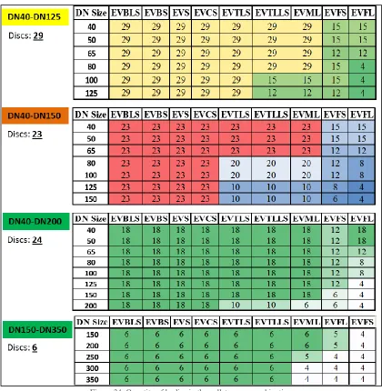
From the observations the number of bodies per type and per size that could be placed in the pallet was determined.
Figure 31: No. of bodies in the pallet.
The quantity of sizes up to DN 125 that could be accommodated is quite good, whereas the numbers are not good enough for sizes above DN150. Hence a new analysis of the position had to be done, and after discussing with members involved in the project a check was performed to check if the sizes DN150-D200 could be combined with sizes of DN40-DN125. Another reason for including these sizes in sub-group of DN125 and below was that the top flange diameter remains same up to DN200 for all sizes. Based on the proposal and with reference to the graphs plotted earlier for the respective sub groups. New graphical check was performed for sized DN40-DN150 & DN40-DN200.
From the analysis it was found out that for DN40-DN150 (Appendix. C) it was possible to fit in 23 bodies and for DN40-DN200, 18 bodies could be accommodated. Since, DN40-DN150 combination
DN Size EVBLS EVBS EVS EVCS EVTLS EVTLLS EVML EVFS EVFL
40 25 25 25 25 25 25 25 12 12
50 25 25 25 25 25 25 25 12 12
65 25 25 25 25 21 21 21 12 6
80 25 25 25 21 21 21 21 12 6
100 21 21 21 21 21 21 21 12 6
125 21 21 21 21 17 17 17 8 8
150 7 7 7 7 7 7 7 4 4
200 7 7 7 7 7 7 7 4 4
250 7 7 7 7 7 4 2
300 7 7 7 7 7 4 2 2
25
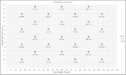
[image:26.595.73.562.88.379.2]was not adding much to the previously determined quantity, it was more convenient to go for DN40-DN200 combination. The position for DN40-DN125 was different from DN150-DN40-DN200 (Appendix. D), it was necessary to find a common point which would help in placing more bodies of all sizes. Ultimately the combined position of all the sizes up to DN200 were determined (Figure 32).
Figure 32: Position of bodies DN40-DN200
Figure 33: Position of bodies DN150-DN350
While determining the quantity that could be placed, it was found that the disc fixture orientation along the width and parallel to the bodies was no longer a good option, as it lead to lesser no. of disc with respect to the bodies. The new optimum orientation was along the length and perpendicular to the body (Figure 26) (for DN40-DN200) and parallel to the body (Figure 27) (for DN150-DN350).
[image:26.595.74.558.408.700.2]bodies is 6, the reason being an optimum position had to be determined so that more bodies of sizes like EVFS, EVFL & EVML could be placed and also this pallet could be used for combining orders having sizes from DN150-DN350.
Figure 34: Quantity of bodies in the pallet as per combination.
From the presented numbers, it was decided to have three different pallets, for sub group DN 40-DN125, DN40-DN200 & DN150-DN350.
27
5
Holding the Bodies in position;
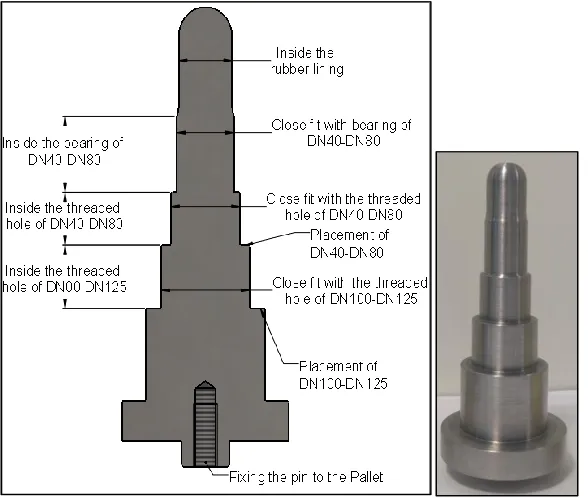
Even though the earlier design of the pin seemed to be a viable solution, it needed more critical thinking. Also, that the different sizes of bodies were combined there was a need to come up with a new design of pin that could be used for the combination of sizes.
[image:28.595.73.367.418.667.2]For a more appropriate and reasonably design the bottom hole dimensioning and design was carefully analysed. The Bottom hole is drilled through into the casted body. After the drilling operation, a threading operation is performed and a liner bearing is inserted. The next step is to vulcanize rubber on the inner surface of the body. The vulcanized rubber also accounts for a certain length of the bottom hole. Since, there are variants of bottom hole diameter so are the dimensions of threads, bearing and rubber coating.
Table 4: Dimensional analysis of the bottom hole diameter.
Sub Group Bottom Hole Diameter Diameter x Length after threading Inner Diameter of the bearing Length of the bearing Inner diameter of the rubber coating
1 14 14.5 * 14 12 15 11.8
2 18 18.5 * 14 16 20 15.8
3 25 25 * 16 22 30 21.8
4 34 34 * 16 30 40 29.75
There was a question, if a common pin could be used for all the sizes. The advantage of using one pin for all was ease of mass production and minimized confusion of using different pins. But, the disadvantage was that the single common pin needs to be lengthier to assure placement of all the sizes without interference. Also, this meant that the smallest sized bodies would be resting at the top portion of the pin with more risk of unstable condition. Therefore, pins were designed in 2-Sub-categories, one pin for sizes DN40-DN125 and another for sizes DN150-DN350 (For the initial proposal of having two pallets).
Figure 35: Pin for DN40-DN125 Figure 36: Pin for DN150-DN350
Figure 37: Placement of bodies on the pin (Multiple bodies in one view)
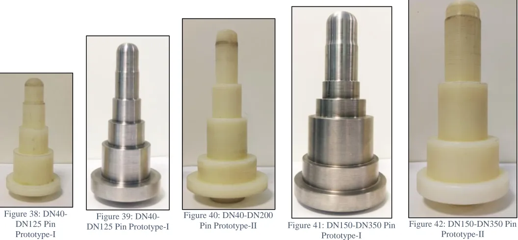
Since the decision of combining DN40-DN200 was made a bit later than the revised pin design, the pin design was further changed. The smaller pin for DN40-DN125 needed another step to place the DN150 & DN200 sizes. Moreover, there was a concern that the part of the pin which holds the body inside the threaded hole might damage the threads and this could affect the quality of the product. Hence, the design of the pin was changed to hold the body inside the bearing and having no contact on the threaded hole. This had a machining advantage and performance was not compromised. New pins could be seen in (Figure 42)
Figure 38: DN40-DN125 Pin Prototype-I
Figure 39: DN40-DN125 Pin Prototype-I
Figure 40: DN40-DN200
Pin Prototype-II Figure 41: DN150-DN350 Pin Prototype-I
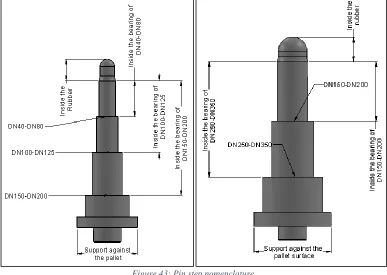
[image:29.595.36.564.429.674.2]29
Figure 43: Pin step nomenclature.
For the disc fixture, the chosen concept was a good start. But, this needed more elaborate design. Earlier the fixture was just a box which had some fillets and slots to keep the disc in place. But some parts of the fixture were non-value adding and could be removed. Also, there was a need to make the fixture adjustable as per the thickness of the disc. Hence, only the portion required to hold the disc firmly was kept in the final design of the fixture. The final design of the fixture had 4 separate modules, and were smaller than the earlier version. Because of the new shape of the modules, there was a need of another fixture to provide rigid support. Therefore, simple sheet metal support plates with slots were designed. With the slots in the support plate the discs could be positioned in order to accommodate the variation in disc size.
[image:30.595.57.523.474.740.2]The fixture geometry was quite complicated and it was difficult to manufacture with conventional machining processes. And for testing a prototype we decided to get the fixtures 3D printed (hence, fixture was made hollow with honeycomb structure).
Figure 44: 1st concept for the Disc fixture (Front View & Top View)
6
Testing and Validation
Prototype Test-I
Now, that the orientation had been finalized, and the design for centring pin & disc fixture was made, it was time to check and confirm if the requirements stated at the beginning of the assignments have been met or not.
6.1.1
Modular Pin Test
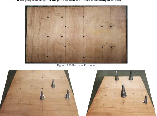
The prototype module for the pallet was made from 8mm thick plywood sheet and holes were drilled on the locations obtained from the positioning analysis. The positions for DN40-D125 DN150-DN350 were made on the same plate because it was the first and basic check. The parameters to be checked from the 1st prototype test were:
If bodies could be placed and removed easily from the pins.
To determine the right dimensions of the pins, by looking at the type of fit. (Loose, Tight or Close fit).
If the bodies were displaced from their initial position when subjected to vibrations.
If there was any interference between the bodies of same type and size when placed at the positions determined.
If the body is easily recognizable for the vision system from the top.
[image:31.595.54.558.323.694.2] If the rotation of the bodies about their axis is really an issue to be addressed. Damage caused to the pins & bodies because of placement and removal. If the proposed design of the pin was correct or it has to be changed further.
Figure 47: Pallet layout Prototype
31
Figure 50: Test setup to check placement of bodies of different sizes. Figure 51: Vision system detecting the bodies underneath.
It was found that the positions determined from the analysis were accurate and the bodies could be placed without interference and it was also possible to have combination of body type and size in one pallet.
The test setup was used in vision system workshop from Cognex (performed at Wouter Witzel) and where the recognition of the bodies by the camera was checked. The camera was able to easily detect the top flange of the bodies and with adjustments in camera position, the presence of other bodies could also be checked.
6.1.2
Modular Disc Fixture Test
For testing the disc fixture, sheet metal parts were made which supported the fixture modules. The sheet metal part was made from laser cutting and slots were made to adjust the gap between the fixture modules. The objective of the test was to determine the optimum face to face distance between the fixture modules to ensure placement of the all the disc (of respective sub-group).
The fixture modules were carefully assembled on the support plates. Three different positions with gap of 10mm, 15mm and 20mm were fixed for DN40-DN200 fixtures. And similarly, for DN 150-DN350 two positions were considered with 25mm & 40mm gap.
The discs were placed in the fixtures to check if they fit in perfectly on the steps as per the corresponding sizes. Also, the possibility of interference was checked. From the test it was clear that for 10mm gap the DN200 disc was not resting on the fillets and got stuck in the gap (Figure 52), whereas with 20 mm gap the DN40 fixture had no supports and it fell down the gap (Figure 523)
Figure 52: DN200 in fixture with gap of 20mm & 10mm respectively. Figure 53: DN40 Disc in fixture with gap of 15mm & 20mm respectively.
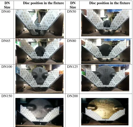
All the other sizes were also checked at all three positions and it was determined that an 15mm gap is optimum to place all the discs in the fixture (Table 5: Placement of discs in the disc fixture with a gap
15 mm Gap
of 15mmThe smaller size discs (DN40-DN80) had a higher possibility of movement (tilting/rotation) about the axis passing through the shaft holes, but it is not a major issue and the system could deal with it.
Table 5: Placement of discs in the disc fixture with a gap of 15mm
DN
Size
Disc position in the fixture
DN
Size
Disc position in the fixture
DN40
DN50
DN65
DN80
DN100
DN125
DN150
DN200
Similarly, the test was performed for DN150-DN350 disc fixture (Appendix F) and it was determined that the 25mm gap is optimum to accommodate all the discs of different sizes.
Other than optimum position, following parameters were also checked.
Characteristic
Description
Analysis
Clearance from the base plate.
The smallest size of the sub-groups is placed on the last step in the fixture and hence it should be clear from the base plate.
33 Gap between the
fixture modules.
The fixture holds the discs on the fillets near the holes for the drive and bottom shaft holes.
Here it was checked that the no other part of the disc is touching the flat faces of the fixture modules in the gap.
Positioning by the fillets
The fixture was given fillets so that the disc could be placed and guided in the fixture.
Here, the curvature on the disc are perfectly tangential to fillets.
Tilting of the disc
There is a possibility that the discs could tilt about their central axis.
In such cases the disc could not be touching the neighbouring disc.
It was found that tilting was not issue.
7
Summary & Current State
The initial goal of the assignment was to design a modular pallet for placing the bodies and discs in order to be picked and placed by a robot on a product carrier on the assembly line. From careful analysis on the type and size of bodies & discs, feasible orientations were proposed and evaluated. In order to attain the finalized orientation, there was a need to design a fixture. Hence, conceptual design of fixtures was proposed and evaluated. The most feasible fixture for body and disc was manufactured for prototyping and performance was evaluated. The disc fixture effectively fulfilled the task for holding the discs in positions, but the design of mounting pin for bodies was revised after 1st
prototype test. The 2nd prototype testing was not rigorous but was only checked for accurate fit and it resulted in accurate fit.
Currently, it is decided that the pallet design and the robot for picking and placing the bodies and discs from the pallet wouldn’t be implemented in the initial phase of project implementation. It would probably be implemented in the next phase of the project based on the performance and productivity of the semi-automated line. Because of the uncertainty, the quantity of the pallets and corresponding fixtures could not be determined. Though the fixtures designs are fulfilling their design requirements to the fullest, but some design modifications have to be done based on the manufacturing process suitable for mass production.
The design of the pallet module along with the fixtures as per the sub-group is completed and requires a full-scale testing to check the compatibility and operating efficiency along with the robot.
8
Conclusion
Based on the Testing performed, the following conclusion were derived:
1. The proposed designs for mounting pin and modular fixture fulfil the initial requirements.
The mounting pin for the bodies was designed to mount bodies of different sizes. The body rests on the pin on the counter bored hole at the bottom. The clearance between the pin and the split sleeve bearing eases the mounting and removal of the bodies on and from the pin. The pins are robust enough to carry the weight of the bodies, but dynamic testing (under real time usage conditions) of the pins has to be done.
The fixture for the disc firmly holds all the types and sizes of discs in their position. The profile of the disc fixture is tangentially in contact with the profile of the disc and it ensures minimum movement. The support plates are effective in bearing the weight of the disc and it is equally distributed on all four modules and hence provides stability.
2. The optimum gap between fixture modules for disc fixture.
The prototype testing of the disc fixtures also helped determine the optimum position to fasten the fixture modules. For DN40-DN200 size discs the optimum gap was 15mm and for DN150-DN350 size discs it was 25mm. With this gap the convex and flat disc types could be placed without any adjustment in the gap between the modules.
The discs always remained inside the fixture and hence there was no possibility of contact with neighbouring discs.
3. Full size pallet could not be tested because of the uncertainty of automating the entire process in the initial phase. Hence, a virtual testing was performed in Solidworks to ensure that the bodies and discs could be placed on determined positions without any interference.
From a full size assembled model, it was clear that there was sufficient space between two adjacent bodies and discs to let the gripper fingers to make a full stroke.
Combination of different sized bodies and discs was also tested which confirmed that it is possible to combine different orders.
35
[image:36.595.83.518.39.604.2]9
Technical Drawings
37
39
41
43
Figure 62: Disc Fixture Assembly DN150-DN350
Figure 64:Pallet module Lay-In DN40-DN125 Figure 65:Pallet module Lay-In DN40-DN200
[image:45.595.160.431.289.741.2]45
[image:46.595.29.574.23.796.2]Figure 67: Modular Pallet assembly- DN40-DN200
10
References
I. http://www.weepallet.com/plastic-pallet-manufacturing-process/ II. https://www.wouterwitzel.nl/about-us/
III. https://schunk.com/de_en/gripping-systems/seriesaccessory/pgn-plus/product/699-0371108-pgn-plus-240-1/
47
11
Appendix
B.
Detailed dimensions of the discs
Size Pressure Class
Distance between flat surfaces
Diameter of the disc
Pin hole
Diameter Size Pressure Class
Maximum Thickness
Thickness at the tip
Thickness at the centre
L Dϕ d Tmax Tt Tc
DN40 P16 35.3 40.3 12 DN40 FORGED 17 4 5
DN50 P16 COATED 44.15 49.5 12 DN50 Casted 23 4 6
DN50 P20 45.05 50.4 12 DN50 p16-Duplex 23 4.5 4.5
DN50 P25 45.35 50.7 12 DN50 P16-Bronze 23 4.5 4.5
DN65 P0 60.8 62.7 12 DN50 P16-SS 23 4.5 4.5
DN65 P6 60.8 65.2 12 DN65 Casted 23 4.4 7
DN65 P10 Halar coated 59.4 63.8 12 DN65 Bronze 23 7 12
DN65 P16 60.8 65.2 12 DN65 Forged 23 4.4 7
DN65 P16 COATED 60.2 64.6 12 DN65 p16-Duplex 23 4 6
DN65 P20 61.1 65.5 12 DN65 P16-SS 23 4 8
DN80 P0 76.15 77.8 12 DN80 P25-Sand Casted 23 5 11.5
DN80 P10 Halar coated 75.15 79.1 12 DN80 P16-SS 23 5 10
DN80 P16 76.15 80.1 12 DN100 Casted 27 5 8
DN80 P16 COATED 75.55 79.5 12 DN100 Bronze 27 5.5 16
DN80 P20 76.6 80.6 12 DN100 P16-SS 27 5.5 12.5
DN80 P25 76.85 80.8 12 DN125 Casted 27 4.7 8
DN100 P0 94.8 97.7 16 DN125 Forged 27 5 10
DN100 P6 94.8 99.7 16 DN125 P16-Bronze 27 5.5 14.5
DN100 P10 Halar coated 93.8 98.7 16 DN125 P16-SS 27 5.5 16
DN100 P16 95.2 100.1 16 DN125 p16-Duplex 27 5.5 12.5
DN100 P16 COATED 94.6 99.5 16 DN150 Casted 35 5.5 20.7
DN100 P20- 95.6 100.5 16 DN150 Forged 35 5.4 10
DN125 P0 120.8 122.7 16 DN150 Bronze 35 6 17.5
DN125 P6 120.77 124.85 16 DN150 P25-Raw Machined 35 6 12
DN125 P10 Halar coated 119.87 123.95 16 DN150 P16-SS 35 6 19.5
DN125 P16 121.27 125.35 16 DN150 p16-Duplex 35 6 15
DN125 P16 COATED 120.67 124.75 16 DN200 Casted 41 6.7 13
DN125 P25 122.1 126.05 16 DN200 P16-Forged 41 6.7 12
DN150 P0 144.6 147.8 22 DN200 Bronze 41 7 23
DN150 P6 144.6 149.475 22 DN200 P16-SS 41 7 26
DN150 P6 Halar coated 143.2 148.08 22 DN200 p16-Duplex 41 7 20
DN150 P10 145 149.9 22 DN250 Casted-BL-BL 51 14 14
DN150 P10 Halar coated 144.3 149.175 22 DN250 P16-Casted 50 12 50
DN150 P16 145.3 150.175 22 DN250 P16-SS 51 8 32
DN150 P16 COATED 144.7 149.575 22 DN250 p16-Duplex 51 8 25
DN150 P20 145.65 150.55 22 DN300 Casted-BL-BL 51 17 17
DN150 P25 146 150.9 22 DN300 P16-Casted 50 12 50
DN150 P25 coated 145.4 150.3 22 DN300 Forged 51 9.1 17
DN200 P0 194.3 196.8 22 DN300 p16-convex 52 12 50
DN200 P6 194.3 198.6 22 DN300 p16-Duplex 51 9 30
DN200 P10 194.6 198.9 22 DN300 P16-SS 51 9 38
DN200 P10 Titaan Gelast 195.05 199.35 22 DN300 P25-Forged 51 9 25
DN200 P16 195.05 199.35 22 DN350 Forged 53 10 20
DN200 P20 195.4 199.7 22 DN350 p16-Duplex 50 12 53
DN200 P25 195.75 200.05 22 DN350 P-Forged-ProfielKlep 51 10 20
DN200 P25 coated 195.15 199.45 22 DN350 P25-Casted 72 12 60
DN250 P0 243.3 248 30
DN250 P6 243.6 249.7 30
DN250 P6 sphere 243.3 250 30
DN250 P6 sphere coated 243.3 249 30
DN250 P10 Sphere 243.6 250 30
DN250 P10 Halar coated 242.5 248.9 30
DN250 P10 coated 242.9 249.3 30
DN250 P16 243.9 250.3 30
DN250 P16 Sphere 243.6 250.3 30
DN250 P25 244.4 250.8 30
DN250 P25 coated 244.6 251 30
DN300 P0 292.1 295 30
DN300 P6 sphere 292.1 297.7 30
DN300 P6 sphere coated 291.4 297.2 30
DN300 P6 coated 292.1 297.7 30
DN300 P10 292.5 298.3 30
DN300 P10 Halar coated 292.1 297.9 30
DN300 P16 292.9 298.7 30
DN300 P16 Sphere 292.9 298.7 30
DN300 P16 Sphere COATED 292.9 298 30
DN300 P20 Coated 292.5 298.3 30
DN300 P25 293.5 299.3 30
DN300 P25 Sphere 293.5 299.3 30
DN300 P25 Sphere coated 292.7 298.5 30
DN350 P2.5 330 335.4 30
DN350 P6 sphere 330 30
DN350 P10 330.3 335.7 30
DN350 P16 330.65 336 30
49
C.
Position analysis for DN200-DN350
Figure 69: Position of bodies of DN200
[image:50.595.73.527.49.599.2]D.
Pallet Combination for different sized bodies
Figure 71: Positioning check for DN40-DN150
[image:51.595.74.522.348.595.2]51
E.
Disc fixture concept grading
F.
DN150-DN350 Disc Fixture Position check.
DN
Size
Disc position in the fixture
DN
Size
Disc position in the fixture
DN150
DN250
DN200
DN300
DN350
G.
Pallet Manufacturing Process
Pallets are widely used all around the world in different sectors to transport goods over short distances or for storing. Conventionally the pallets were made from wood, but over a period of time with advancements in technology and material researches they are made with variety of materials. In general, it could be said that they are made from plastic. The reason to use plastic is that it is cheap, strong, light weight, durability, could be used in different environments and could be easily recycled. Another great advantage being that it can be made in any complex geometry as required for a particular purpose. The wooden pallet has basically one major manufacturing process, in which the wood is sliced in strips/
Weightage
Concept C-1 C-2 C-3 C-4 C-1 C-2 C-3 C-4 C-1 C-2 C-3 C-4 C-1 C-2 C-3 C-4 C-1 C-2 C-3 C-4
Stability 5 5 1 2 4 5 2 5 4 5 2 5 4 5 1 3 4 5 2 4 4
Ease of use (operator &
Cartesian system0 3 5 2 1 4 5 4 2 5 4 2 3 5 5 3 4 5 5 3 3 5
Compatibility (different
sizes of discs) 5 1 5 5 3 3 4 3 5 5 5 3 5 3 5 3 5 3 5 4 5
Robustness 4 5 3 1 5 5 2 5 4 5 2 5 4 5 2 4 4 5 2 4 4
Manufacturing &
Maintenance Feasibility 3 4 1 5 4 3 2 2 4 2 3 3 5 2 1 2 3 3 2 3 4
Total Score 77 51 57 79 84 56 72 88 88 58 78 91 81 50 64 85 83 58 74 88
Aggregate
Parameters
blocks of desired thickness and the joining is done with fasteners like nails, screw, etc. On the contrary there are variety of processes that are used to produce a plastic pallet, some of which are listed below and elaborated further. Key manufacturing processes:
1.
Injection moulding2.
Thermoforming3.
Blow moulding4.
Compression moulding5.
Rotational moulding6.
Profile extrusionI. INJECTIONMOLDING
It is one of the most popular processes of shaping plastics to a desired shape and size. This process is best suited for large scale production sizes, especially where the same design has to be produced several times. Generally, injection moulding process involves the following key steps:
Raw material is fed into the machines through a hopper. Heater bands and frictional force melts the plastic material.
Hot plastic in liquid state is injected with a nozzle into the mild cavity, where it cools and hardens. Two Types of injection moulding are possible
-Low Pressure Structural Foam Moulding: The mould cavity is injected with plastic pallet material and an inert gas. Heating a mixture of nitrogen gas and polypropylene activates blowing agents. This produces a cellular core surrounded with a rigid plastic material.
-High Pressure Injection Melding: Used for high-density polyethylene (HDPE) plastics. It is a precise process and requires no/minimum post processing
II. THERMOFORMING
The plastic is heated to a pliable temperature then it is formed over a mould and allowed to cool. Thermoforming plastic pallet is a three-step process that involves:
Heating the plastic pallet material; this results in an extruded plastic sheet with a desired thickness. Forming either one or two sheets against the mould, while evacuating air between the sheet and the
mould. Alternatively, a vacuum suction draws and pushes the heated plastic onto the mould. Allow the formed plastic pallet to cool.
Two types of thermoforming techniques are quite popular:
Vacuum Thermoforming: The plastic pallet is made into desired shape using heat and pressure. The heated plastic material is put over a mould and then it is drawn into the mould by a vacuum. -Pressure Thermoforming: Similar to the vacuum thermoforming. However, in addition to the force/pressure generated by the vacuum, an extra pressure is applied that will force the plastic into the mould.
Good for aesthetic qualities, i.e., it can create greater detail such as textured surface, undercuts, sharp corners, etc. Slow cycle time and cheaper process as compared to injection moulding.
III. BLOWMOLDING
Blow moulding is used for forming hollow parts. The key stages are: Melt the plastic material.
Forming into a tube-like piece of plastic that has a hole on one end where compressed air can pass.
Clamp the hole into a mould.
Blow air in to expand it to take the exact shape of the mould. Allow it to cool and harden.
Parts made from blow moulding don’t get damaged easily and show very little or no damage when accidentally hit by a forklift. Have excellent resistance to impact compared to injection moulded plastic pallets.
IV. COMPRESSIONMOLDING
This a cost effective process as compared to injection moulding. Requires low cost of tooling and labour besides, the process minimizes wastage. The process of manufacturing:
Material is placed into a desired mould
53
Slow process compared to the injection moulding technique.
V. ROTATIONALMOLDING
In this process the plastic materials are ground into small pieces such as powder or granules. Later this is loaded into mould and sealed, heated and rotated in two perpendicular axes. The centrifugal motion assures that every particle is mixed and distributed within the mould. After the pallet can be removed, once the mould cools down.
VI. PROFILEEXTRUSION
The plastic pallets made from this process mainly resemble wood pallets. The plastic is melted and forced through an extruder.
The extruded profile is cut to different sized parts/shapes. Later these are fastened together using nails, heat or welds.
Incorporating fasteners will make the pallet unsafe unlike those made from other processes.