Axial Eccentric SynRel and SPM Motors Analytical
Models Validation Using 3D Finite Element
H. Mahmoud, A. Al-Timimy, M. Degano, M. Di Nardo, N. Bianchi, and C. Gerada
Abstract—This paper deals with the uniform and non-uniform axial eccentricity analyses of the surface mounted permanent magnet and synchronous reluctance machines. The analyses are carried out using an analytical model for each considered machine. Being the axial eccentricity a 3D physical phenomenon, the standard sliding approach used in the analytical models has been validated through accurate 3D FE simulations. The results presented in this paper verify the effectiveness of the analytical approaches quantifying the results deviations respect to the com-putational expensive 3D FE simulations. The results also confirms that synchronous reluctance machines show higher radial forces compared to the surface permanent magnet machines for the same eccentricity level, main geometry and operating condition.
Index Terms—Non-uniform axial eccentricity, Uniform axial eccentricity, Analytical analysis, 3D finite element modelling.
I. INTRODUCTION
Both permanent magnet (SPM) and synchronous reluctance (SynRel) machines are widely used for their respective merits in several low-medium speed applications, such as industrial, traction, household, etc. [1], [2]. The SPM machines, which make use of high energy density permanent magnets (PMs), show the highest torque density and efficiency. However the use of rare earth based PMs is also the root of the main dis-advantage of this machine topology, i.e. its high cost [2]–[4]. Consequently both academia and industries have attempted to reduce the use of rare earth PMs both by optimizing the SPM design or adopting other machine topologies. Another design challenge of SPM machines widely addressed in literature regards the reduction of the cogging torque which can be faced applying several methods [5]–[8].
The interest towards SynRel machines in the last years is justified by its torque density, comparable to the induction motor one, and the absence of rare earth PMs and so its lower and more stable cost [9], [10]. High torque ripple and low power factor are the most important disadvantages of SynRel machines. The first one can be greatly reduced by properly designing the rotor geometry [11]–[14], while the power factor can be significantly increased by inserting small amount of PMs (also rare earth free materials such as Ferrite PMs) inside the rotor flux barriers [10], [15].
H. Mahmoud, A. Al-Timimy, M. Degano, M. Di Nardo, and C. Gerada are with the Department of Electrical and Electronic Engineering, University of Nottingham, NG72RD, Nottingham, Uk, M. Degano and C. Gerada are also with the Department of Electrical and Electronic Engineering, Univer-sity of Ningbo China, Ningbo, China, [email protected], [email protected], [email protected] and [email protected].
N. Bianchi is with the Department of Industrial Engineering, University of Padova, Via Gradenigo, 6A, 35131 Padova (Italy), [email protected].
A relevant amount of literature has lately addressed the more ”practical” problem of the worsening of the electromagnetic performance related with manufacturing and assembling pro-cesses. One of the possible root of performance alteration is due to the manufacturing tolerance of the bearing housings and the accuracy of the rotor/stator assembly [16], [17].
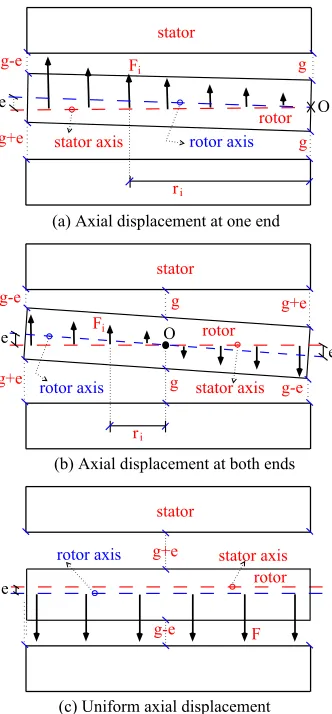
The latter mainly causes the rotor axis to be not perfectly placed on the stator axis. In particular, Fig. 1 (a) shows an axially non-uniform eccentricity in which only one end of the machine is eccentric, Fig. 1 (b) displays an axially non-uniform eccentricity in which both ends of the motor are equally eccentric, and Fig. 1 (c) reports an axially uniform displacement of the rotor axis with respect to the stator axis. Besides, the above described geometrical cases, the axis of rotation can coincide with the rotor axis or with the stator axis. The first case is called static eccentricity while the second is the dynamic eccentricity [18], [19]; a combination of both cases can obviously occur.
The effect of all the above described eccentricity cases for SPM machines have been widely addressed in [20], while the same analyses on the SynRel machines have not received the same attention. In particular, late studies [21], [22] have analysed the axially uniform eccentricity on SynRel machines. In [20], [23], also the non-uniform axial eccentricity effect on both SPM and SynRel machines have been investigated subdividing the rotor axial length into a finite number of slides. The respective analytical or 2D FE model is then applied to each axial slide and consequently the total magnetic force caused by the eccentricity can be computed.
Being the non-uniform axial eccentricity a 3D physical phe-nomenon, it is important to compare the sliding approach used in the analytical models (and in the 2D FE) through an accurate 3D FE simulation. Therefore, this paper focuses on the 3D modelling of both machines in different axial eccentricity cases shown in Fig. 1. The developed comparative study, carried out on both machines, allows determining the accuracy of both 2D analytical model and 2D FE solution with respect to the more complex and time consuming 3D FE simulation. The paper structure is as following: (a) section II briefly describes the 2D analytical models of both eccentric machines, (b) section III shows the 3D modelling of the both machines in the three different cases of rotor axial displacement, and (c) section IV presents the comparison between the results of the 3D and the 2D models, as well as, between the two eccentric machines.
II. THE2D ANALYTICALMODELS
Con-r
(a) Axial displacement at one end
stator
i e
g
g g-e
g+e stator axis rotor axis rotor Fi
O
stator
O
ri
g-e
g+e g-e
g+e
e
e
Fi
g
g rotor
rotor axis stator axis
(b) Axial displacement at both ends
stator
(c) Uniform axial displacement
g-e g+e
e rotor
[image:2.612.91.257.53.410.2]F stator axis rotor axis
Fig. 1:Side view of an electric motor shows the three different axial eccentricity cases.
sequently the magnetic radial pressure on the rotor periphery becomes asymmetric leading to an unbalanced magnetic force acting on the rotor.
The mathematical expression describing the non-uniform air-gap length, in case of static eccentricity, was firstly pro-posed in [24]–[26]. Analysing Fig. 2, it can be recognized that the minimum air-gap length is fixed with the rotor rotation. Thus, the air-gap length variation does not depend on the rotor position and can be expressed as:
g(θs) =g−ecos(θs) =g[1−∆ cos(θs−θe)] (1)
where e is the eccentricity distance between the stator axial center and the rotor axial center, ∆ = e/g is the relative eccentricity, given by the ratio of the rotor displacement and the air-gap, θe andθs are the initial angle of the eccentricity and the coordinate angle referring to the stator stationary reference frame (mechanical degrees), respectively.
In case of dynamic eccentricity, the analytical formulation of the air-gap length as function of the rotor position has been first presented in [27]. In particular, it can be geometrically derived analyzing Fig. 3, as
g(θs) =g−ecos(θs−θm) =g[1−∆ cos(θs−θm−θe)] (2)
whereθmis the rotor position angle (mechanical degrees).
stator
stator center
rotor
air-gap
rotor center
Dr D
a-axis x-axis
e
e
Fig. 2: Air-gap length variation with the rotor rotation, in case of static eccentricity.
(b) at θm= 90
(a) at θm= 0 (c) at θm= 180
stator
stator stator
rotor rotor
e rotor
air-gap air-gap
air-gap
e
e g-e g-e
[image:2.612.328.550.80.270.2]g-e
Fig. 3: Air-gap length variation with the rotor rotation, in case of dynamic eccentricity, withθe= 0◦.
In the following, the influence of such variation on the com-putation of the air-gap flux density distribution is discussed on both SynRel and SPM motors.
A. Eccentric SynRel machine
As reported in [21], from the equivalent magnetic network, the flux density distribution in the air-gap is computed as
Bg(θs) =µ◦
−Us(θs) +Ur(θs)
g(θs) (3)
whereUs(θs)andUr(θs)are the stator and rotor scalar mag-netic potential distributions, respectively. Their computations are illustrated in details in [21], [23].
As highlighted in [21], the computation of the rotor scalar magnetic potential, and hence, Bg(θs) requires to integrate the expression shown in (3). However, in eccentricity case, the symbolic integration of Bg(θr) is complicated due to the cosine function in the denominator. Therefore, with the aim of simplifying this integration, the air-gap is split into different regions. Then, the integration is implemented on each region considering the average of air-gap length variation in each region (¯g), i.e., as a constant value. The number of these regions (ng) depends on the number of pole pairs (p) and
number of flux-barriers per pole (Nb). It can be expressed as
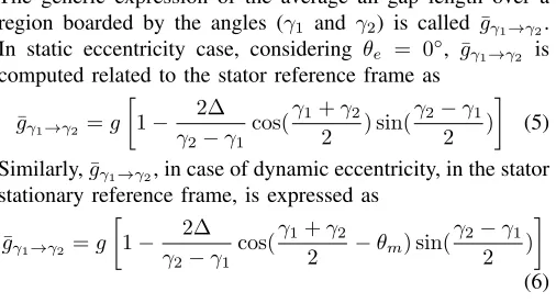
[image:2.612.313.568.319.412.2]The generic expression of the average air-gap length over a region boarded by the angles (γ1 and γ2) is called g¯γ1→γ2.
In static eccentricity case, considering θe = 0◦, ¯gγ1→γ2 is
computed related to the stator reference frame as
¯
gγ1→γ2 =g
1− 2∆
γ2−γ1
cos(γ1+γ2 2 ) sin(
γ2−γ1
2 )
(5)
Similarly,¯gγ1→γ2, in case of dynamic eccentricity, in the stator
stationary reference frame, is expressed as
¯
gγ1→γ2=g
1− 2∆
γ2−γ1
cos(γ1+γ2
2 −θm) sin(
γ2−γ1
2 )
(6)
B. Eccentric SPM machine
Analyzing Fig. 4, which shows a cross section of an eccen-tric SPM machine, it can be deduced that the air-gap length variation can be expressed by the variation of the internal radius of the stator according to the rotor centerRsr(θs).
The air-gap flux densityBg(θs)can be computed using the model presented in [20] in case of concentric machine. In such healthy case, the air-gap flux density depends on the stator inner radiusRs. By simply replacingRswithRsr, it is
possible to determine Bg(θs)also for the eccentric machine
using the same analytical model. The stator radius in the new reference frame can be computed from Rs and the angle θs.
In particular, considering a generic point P on the stator periphery, its Cartesian coordinates in the stator reference frame are given by:
Pxs=Rscos(θs) and Pys=Rssin(θs) (7)
Hence, the coordinates of point P at rotor reference are computed as
Pxr =Pxs−e and Pyr =Pys (8)
Then, Rsr andθsr are given by:
Rsr=qP2
xr+Pyr2 and θsr = tan
−1(Pyr/Pxr)
(9) Finally,Rsr(θsr)can be computed forθsr varying from0◦to
360◦ which cover the air-gap length variation.
The radial magnetic pressure and force on the overall rotor, in case of uniform axial eccentricity, can be computed, as reported in [21].
C. Sliding approach
As mentioned in the introduction, the computation of the radial forces in case of non-uniform axial eccentricity of both machines can be carried adopting the sliding approach. The latter simply consists in sub-diving the rotor into a finite number of axial slides [20], [21], [23]. As a consequent, the eccentricity of each rotor slide can be considered as uniform axial eccentricity, and hence, the force can be easily computed using the above described analytical models. Once the radial forces on each axial slides have been calculated, the total force is simply the sum of all the forces. The same sliding approach is used with the 2D FE models. Thus, it is important to implement the 3D FE modelling to validate the results of both 2D analytical and FE models, specially in case of non-uniform axial eccentricity.
x-axis y-axis
Or Os
rotor
permanent magnet stator
air-gap
e
P
Rsr
= 0 θm
= 0 θe
= 0 θs
[image:3.612.327.550.57.250.2]θs Rs
Fig. 4:Cross section of eccentric SPM machine.
III. 3D FINITEELEMENTANALYSIS
The eccentricity of both SynRel and SPM machines have been simulated via 3D FE analysis since it allows consid-ering the non-uniform axial displacement without neglecting any electromagnetic components (such as the end winding). The use of 3D FE analysis is usually discouraged due to the extremely high computational cost and to the long time required to set up the model [28]. The FE analyses have been obviously carried out replicating as much as possible the hypotheses of the analytical modeling, i.e. the stator replaced by an equivalent current sheet, an infinite iron permeability. These assumptions lead to simplify the 3D FE models of both machines, as shown in Fig. 5, and reduce the simulation time.
current sheet
flux-barrier
shaft
iron ribs rotor
air-gap
current point
(a) SynRel
current sheet
magnet
shaft
rotor air-gap current point
[image:3.612.50.303.63.201.2](b) SPM.
Fig. 5:3D Cross-section of (a) SynRel and (b) SPM motors.
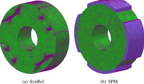
Fig. 5 shows the 3D cross-section of the two machine topologies while the generated 3D-mesh of both machines rotors are presented in Fig. 6.
[image:3.612.315.563.474.620.2](a) SynRel. (b) SPM.
Fig. 6:Mesh density map of (a) SynRel and (b) SPM motors.
with the highest energy density), it is a common practice to subdivide this component into several layers (i.e. hollow concentric cylinders) and impose the mesh vertexes on the peripheries of such layers. In this case, the air-gap has been divided into four layers as shown in Fig. 7 (a) for the concentric case, as recommended by the adopted FE suit [29]. In the case of concentric machines, the thicknesses of each air-gap layer are simply all equal to each other, i.e.
d = g / 4 . However in case of eccentric machines, the thickness of each air-gap layerdihas to be properly calculated
in order to avoid the overlapping of two or more components. The easiest way to avoid this modelling problem is to consider the three air-gap layers nearer to the rotor with an equal thickness of di = (g−e) / 4 . By doing so, the three inner air-gap layers will feature a constant thickness and only the outer one will have a non-constant thickness reaching a minimum of di (so bigger than zero) in the point where the air-gap is minimum. The mesh at the maximum and minimum air-gap lengths are shown in Fig. 7 (b) and Fig. 7 (c) for the sake of clarity.
Regarding the implementation of the axially non-uniform eccentricity, to simplify the modelling, instead of moving the rotor within the stator, it has been decided to fix the rotor and move the stator current sheet (defined by a lower number of points). Fig. 8 clarifies how the current sheet has been moved in the eccentricities cases depicted in Fig. 1.
IV. RESULTSCOMPARISON
This section presents the results of the 2D analytical models of both SynRel and SPM motors at the different axial eccen-tricity scenarios. The results of both models are validated by both 2D and 3D FE analyses. In addition, the two machines are compared together in the aforementioned three eccentricity cases. For fair comparison, the two machines have the same main stator geometry, i.e, Qs, Lstk, p, and g. Table. I and Table. II report the main geometrical data of SynRel and SPM motor, respectively. For the following analysis, the eccentricity
e is set equal to0.2.
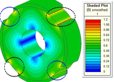
Fig. 9 and Fig. 10 show the 3D flux density map of the SynRel and SPM motors at the rated speed, in case of no eccentricity. It is noted that there is a symmetric distribution of
Inner air-gap (
rotor)
Middle ai
r-gap (
rotor)
Middle ai
r-gap (
stator)
Outer air-gap (stator)
Middle ai
r-gap (
stator)
Outer air-gap (stator)
g g + e g - e
Inner air-gap (
rotor)
Middle ai
r-gap (
rotor)
[image:4.612.55.295.69.210.2](a) (b) (c)
Fig. 7: Mesh in (a) the uniform air-gap length, i.e., healthy case, (b) the maximum air-gap length in case of eccentricity, and (c) the minimum air-gap length in case of eccentricity, respectively.
(x, y+e) Lstk
(a)
current point
(x, y)
(x, y)
(b) (c)
Lstk Lstk
[image:4.612.323.553.250.362.2](x, y-e) (x, y+e)
Fig. 8:The current sheet in case of (a) uniform axial displacement and non-uniform axial displacement between the rotor and stator axes at (b) one end and (c) both ends.
TABLE I:The main geometrical data of the both machine.
g 0.35mm Rs 62.5mm Rr 62.15mm Lstk 40mm
p 4
[image:4.612.376.497.514.601.2]Qs 36
TABLE II:Geometrical data of the SPM machine.
tsleev 0.15mm
gspm=g+tsleev 0.5mm
Rs 62.5mm
Rm 62mm
hm 5mm
Rr 57mm
αp 0.67
Brem 0.905T
the flux density for both motors, as highlighted by the dotted circles in both figures. As expected, the radial force on the overall rotor is equal to zero.
A. Uniform axial displacement
Fig. 9:3D Flux density map of concentric SynRel motor.
[image:5.612.83.270.235.370.2]Fig. 10:3D Flux density map of concentric SPM motor.
Fig. 11: 3D Flux density map of SynRel motor in case of uniform axial eccentricity at the right hand side.
The air-gap flux density distribution, resulted from the analytical, 2D and 3D FE models of both motors, are compared together, as shown in Fig. 13 and Fig. 14. It is noted that there are good agreement between the results of both analytical models and their corresponding 2D and 3D FE analyses.
[image:5.612.313.569.249.357.2]Fig. 15 and Fig. 16 show the radial magnetic force acting on the rotor of both motors under no-load and load operating conditions. Also these figures show a satisfactory agreement between the analytical models of the two motors and their corresponding 2D and 3D FE analyses. Comparing the radial forces on the rotor of both motors, shown in Fig. 15 and Fig. 16, it is recognized that the SynRel is worsen than the
Fig. 12: 3D Flux density map of SPM motor in case of uniform axial eccentricity at the right hand side.
θ
s [mech degrees]
0 50 100 150 200 250 300 350
Air-gap flux density [Tesla] -2
-1 0 1 2
Analytical 2D FE 3D FE
Fig. 13: Air-gap flux density distribution of SynRel motor in case of uniform axial eccentricity at the right hand side.
θ
s [mech degrees]
0 50 100 150 200 250 300 350
air-gap flux density [Tesla] -1
-0.5 0 0.5 1
[image:5.612.312.568.408.514.2]Analytical 2D FE 3D FE
Fig. 14: Air-gap flux density distribution of SPM motor in case of uniform eccentricity at the right hand side.
SPM motor, in case of uniform axial eccentricity.
Eccentricity [mm]
0 0.05 0.1 0.15 0.2
Fr [N]
0 500 1000
analytically at load 2D FE at load 3D FE at load analytically at no load 2D FE at no load 3D FE at no load
[image:5.612.82.269.409.551.2] [image:5.612.314.566.599.705.2]Eccentricity [mm]
0 0.05 0.1 0.15 0.2
Fr [N]
0 20 40 60 80 100 120
analytically at no load 2D FE at no load 3D FE at no load
(a) under no-load condition.
Eccentricity [mm]
0 0.05 0.1 0.15 0.2
Fr [N]
0 20 40 60 80 100 120
analytically at load 2D FE at load 3D FE at load
[image:6.612.345.531.58.203.2](b) under load condition.
Fig. 16:Radial magnetic force acting on the rotor of SPM motor in case of uniform eccentricity at the right hand side under (a) no-load and (b) load conditions.
B. Non-uniform axial displacement
As highlighted in Fig. 1 (a) and Fig. 1 (b), the air-gap length exhibits non-uniform distribution through the axial length of the motor. Thus, the axial air-gap flux density distribution is non-uniform. The suitable presentation of this flux density variation is the 3D flux density map.
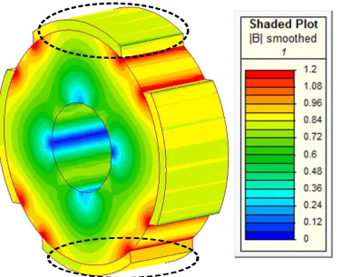
1) at one end: Fig. 17 and Fig. 18 show the 3D flux
density maps of SynRel and SPM motors, respectively. Referring to the dotted circle shown in the upper parts of the two maps, the flux density is high at the minimum air-gap length, i.e. g−e, and is gradually reduced through the axial length till the desired air-gap lengthg. In addition, regarding to the lower part of both motors, the flux density is low at air-gap length equal to g+e, then it is increased gradually till reach the flux density of the healthy case, i.e., at air-gap length equal tog.
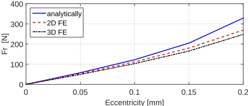
The radial magnetic forces acting on the rotors of both motors are computed form the analytical models, 2D and 3D FE analyses, as shown in Fig. 19 and Fig. 20. Once again, a good agreement between the analytical models and the FE analyses is achieved.
Fig. 17: 3D Flux density map of SynRel motor in case of non-uniform axial displacement at one end.
2) at both ends: Similarly, the 3D flux density maps of
[image:6.612.54.297.61.184.2]SynRel and SPM motors are shown in Fig. 21 and Fig. 22, respectively. For the upper part of both motors, it is noted that
Fig. 18:3D Flux density map of SPM motor in case of non-uniform axial displacement at one end.
Eccentricity [mm]
0 0.05 0.1 0.15 0.2
Fr [N]
0 100 200 300 400
[image:6.612.313.567.249.358.2]analytically 2D FE 3D FE
Fig. 19:Radial magnetic force acting on the rotor of SynRel motor in case of non-uniform axial displacement at one end.
Eccentricity [mm]
0 0.02 0.04 0.06 0.08 0.1 0.12 0.14 0.16 0.18 0.2
Fr [N]
0 20 40 60
analytically 2D FE 3D FE
Fig. 20:Radial magnetic force acting on the rotor of SPM motor in case of non-uniform axial displacement at one end.
the flux density exhibits its maximum value at air-gap length equal tog−e, then it is gradually reduced to its minimum value at air-gap length equal tog+e. The contrary is recognised for the lower parts of both motors.
As expected the radial forces acting on the rotor of both machines in case of non-uniform axial displacement at both ends is equal to zero.
V. CONCLUSIONS
[image:6.612.315.565.404.506.2] [image:6.612.83.268.527.671.2]Fig. 21: 3D Flux density map of SynRel motor in case of non-uniform axial displacement at both ends.
Fig. 22:3D Flux density map of SPM motor in case of non-uniform axial displacement at both ends.
with both analytical models, in case of non-uniform axial eccentricity, is validated by the 3D FE analyses.
The axial flux density variations of both motor are illustrated by 3D maps at the different eccentricity cases. In addition, it is noted that the radial forces estimated by the analytical models have good agreement with those resulted from both 2D and 3D FE analyses. Finally, the results of the two analytical models are compared together in order to decide which motor is the worst in the different eccentricity cases. As expected, it can be concluded that the SynRel motor is the worst at all cases of eccentricity.
REFERENCES
[1] G. Pellegrino, A. Vagati, P. Guglielmi, and B. Boazzo, “Performance comparison between surface-mounted and interior PM motor drives for electric vehicle application,”IEEE Transactions on Industrial Electron-ics, vol. 59, no. 2, pp. 803–811, Feb 2012.
[2] A. Vagati, B. Boazzo, P. Guglielmi, and G. Pellegrino, “Design of ferrite-assisted synchronous reluctance machines robust toward demagnetiza-tion,”IEEE Transactions on Industry Applications, vol. 50, no. 3, pp. 1768–1779, May 2014.
[3] P. Guglielmi, B. Boazzo, E. Armando, G. Pellegrino, and A. Vagati, “Permanent-magnet minimization in PM-Assisted synchronous reluc-tance motors for wide speed range,” IEEE Transactions on Industry Applications, vol. 49, no. 1, pp. 31–41, Jan 2013.
[4] B. Boazzo, A. Vagati, G. Pellegrino, E. Armando, and P. Guglielmi, “Multipolar ferrite-assisted synchronous reluctance machines: A general design approach,”IEEE Transactions on Industrial Electronics, vol. 62, no. 2, pp. 832–845, Feb 2015.
[5] Z. Q. Zhu and D. Howe, “Influence of design parameters on cogging torque in permanent magnet machines,” inConference Record of IEEE International Electric Machines and Drives, May 1997, pp. MA1/3.1– MA1/3.3.
[6] N. Bianchi and S. Bolognani, “Design techniques for reducing the cogging torque in surface-mounted PM motors,”IEEE Transactions on Industry Applications, vol. 38, no. 5, pp. 1259–1265, Sep 2002. [7] L. Dosiek and P. Pillay, “Cogging torque reduction in permanent magnet
machines,”IEEE Transactions on Industry Applications, vol. 43, no. 6, pp. 1565–1571, Nov 2007.
[8] N. Chen, S. L. Ho, and W. N. Fu, “Optimization of permanent magnet surface shapes of electric motors for minimization of cogging torque using fem,”IEEE Transactions on Magnetics, vol. 46, no. 6, pp. 2478– 2481, June 2010.
[9] M. Barcaro and N. Bianchi, “Interior PM machines using ferrite to substitute rare-earth surface pm machines,” in2012 XXth International Conference on Electrical Machines, Marseille, France, Sept 2012, pp. 1339–1345.
[10] N. Bianchi, H. Mahmoud, and S. Bolognani, “Fast synthesis of per-manent magnet assisted synchronous reluctance motors,” IET Electric Power Applications, vol. 10, no. 5, pp. 312–318, 2016.
[11] A. Vagati, M. Pastorelli, G. Francheschini, and S. C. Petrache, “Design of low-torque-ripple synchronous reluctance motors,”IEEE Transactions on Industry Applications, vol. 34, no. 4, pp. 758–765, Jul 1998. [12] D. Ionel, “Interior permanent magnet motor including rotor with unequal
poles,”US Patent, 8,102,091, 2102.
[13] N. Bianchi, S. Bolognani, D. Bon, and M. D. Pre, “Rotor flux-barrier design for torque ripple reduction in synchronous reluctance and pm-assisted synchronous reluctance motors,”IEEE Transactions on Industry Applications, vol. 45, no. 3, pp. 921–928, May 2009.
[14] M. Degano, E. Carraro, and N. Bianchi, “Selection criteria and robust optimization of a traction PM-Assisted synchronous reluctance motor,” IEEE Transactions on Industry Applications, vol. 51, no. 6, pp. 4383– 4391, Nov 2015.
[15] N. Bianchi and H. Mahmoud, “An analytical approach to design the PM in PMAREL motors robust toward the demagnetization,” IEEE Transactions on Energy Conversion, vol. 31, no. 2, pp. 800–809, June 2016.
[16] L. Gasparin and R. Fiser, “Intensity of the native and additional harmonic components in cogging torque due to design parameters of permanent-magnet motors,” inInternational Conference on Power Electronics and Drive Systems (PEDS), Taipei, Taiwan, Nov 2009, pp. 1062–1067. [17] I. Coenen, M. van der Giet, and K. Hameyer, “Manufacturing tolerances:
Estimation and prediction of cogging torque influenced by magnetization faults,”IEEE Transactions on Magnetics, vol. 48, no. 5, pp. 1932–1936, May 2012.
[18] H. Mahmoud and N. Bianchi, “Comparison between synchronous re-luctance and interior permanent magnet motors with eccentricity,” in IEEE Workshop on Electrical Machines Design, Control and Diagnosis (WEMDCD), Torino, Italy, March 2015, pp. 22–27.
[19] ——, “Comparison between synchronous machines with eccentric-ity: Reluctance and permanent magnets,” in International Sympo-sium on Power Electronics, Electrical Drives, Automation and Motion (SPEEDAM), Capri, Italy, June 2016, pp. 394–400.
[20] M. Michon, R. C. Holehouse, K. Atallah, and J. Wang, “Unbalanced magnetic pull in permanent magnet machines,” in 7th IET Interna-tional Conference on Power Electronics, Machines and Drives (PEMD), Manchester, UK, April 2014, pp. 1–6.
[21] H. Mahmoud and N. Bianchi, “Eccentricity in synchronous reluctance motors part I: Analytical and finite-element models,”IEEE Transactions on Energy Conversion, vol. 30, no. 2, pp. 745–753, June 2015. [22] ——, “Eccentricity in synchronous reluctance motors-part II: Different
rotor geometry and stator windings,” IEEE Transactions on Energy Conversion, vol. 30, no. 2, pp. 754–760, June 2015.
[23] ——, “Analytical comparison of synchronous reluctance and surface permanent magnet machines with rotor eccentricity,” inIEEE Energy Conversion Congress and Exposition (ECCE), Sept 2015, pp. 1765– 1772.
[24] S. Swann, “Effect of rotor eccentricity on the magnetic field in the air-gap of a non-salient-pole machine,” Proceedings of the Institution of Electrical Engineers, vol. 110, no. 5, pp. 903–915, May 1963. [25] A. Smith and D. Dorrell, “Calculation and measurement of unbalanced
magnetic pull in cage induction motors with eccentric rotors. i. analytical model,”IEE Proceedings - Electric Power Applications, vol. 143, no. 3, pp. 193–201, May 1996.
[26] D. Dorrell, W. Thomson, and S. Roach, “Combined effects of static and dynamic eccentricity on airgap flux waves and the application of current monitoring to detect dynamic eccentricity in 3-phase induction motors,” inSeventh International Conference on (Conf. Publ. No. 412) in Electrical Machines and Drives, Sep 1995, pp. 151–155.
[27] G. Joksimovic, M. Durovic, J. Penman, and N. Arthur, “Dynamic sim-ulation of dynamic eccentricity in induction machines-winding function approach,”IEEE Transactions on Energy Conversion, vol. 15, no. 2, pp. 143–148, June 2000.
[28] L. Chen, J. Wang, and S. S. Nair, “An analytical method for predicting 3D eddy current loss in permanent magnet machines based on gener-alized image theory,”IEEE Transactions on Magnetics, vol. 52, no. 6, pp. 1–11, June 2016.