Estimating Current Derivatives for Sensorless Motor Drive Applications
David Hind, Mark Sumner and Chris Gerada
THE UNIVERSITY OF NOTTINGHAM
University Park
Nottingham, UK
Tel.: +44 / (0) – 115 951 5549
Fax.: +44 / (0) – 115 951 5616
E-Mail: David.Hind@nottingham.ac.uk
URL:
http://www.nottingham.ac.uk/research/groups/power-electronics-machines-and-control-group/index.aspxAcknowledgements
The authors wish to acknowledge the support provided by the EPSRC Impact Acceleration Account.
Keywords
«Estimation technique», «Field Programmable Gate Array (FPGA)», «Neural network», «Self-sensing control», «Sensorless control».
Abstract
The PWM current derivative technique for sensorless control of AC machines requires current derivative measurements under certain PWM vectors. This is often not possible under narrow PWM vectors due to high frequency (HF) oscillations which affect the current and current derivative responses. In previous work, researchers extended the time that PWM vectors were applied to the machine for to a threshold known as the minimum pulse width (tmin), in order to allow the HF
oscillations to decay and a derivative measurement to be obtained. This resulted in additional
distortion to the motor current New experimental results demonstrate that an artificial neural network (ANN) can be used to estimate derivatives using measurements from a standard current sensor before the HF oscillations have fully decayed. This reduces the minimum pulse width required and can significantly reduce the additional current distortion and torque ripple.
Introduction
The PWM current derivative (PCD) technique
Sensorless control of AC machines is a topic that has attracted a great deal of interest in both academia and industry. The PWM current derivative (PCD) technique is a saliency tracking technique which uses voltage pulses applied under normal PWM operation as test pulses [1, 2], thus no
additional high frequency signals or test pulses are required. Measurements of the current derivative under certain PWM active and null vectors are used to calculate position scalars, Pabc. The position
scalars allow the position vector components, Pαβ, to be calculated from (1) and the rotor position, θ, to
be estimated from (2), where ‘n’ is the number saliency cycles per revolution [1, 2].
Pα=Pa -Pb
2 -Pc
2
Pβ = √3
2 ( P b - Pc )
(1)
θ=1
n tan-1( Pβ
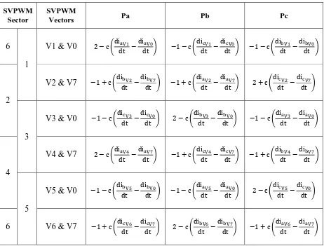
The equations which relate the current derivatives to the position scalars for a star connected machine are given in Table I [1]. A similar set of equations exist for delta connected machines. Details of how these equations are derived can be found in [1-3].
Table I: Equations relating current derivatives and position scalars for each SVPWM
vector for a star connected machine
SVPWM Sector
SVPWM
Vectors Pa Pb Pc
6
1
V1 & V0
2 − c (diaV1dt −
diaV0
dt ) −1 − c (
dicV1
dt −
dicV0
dt ) −1 − c ( dibV1
dt −
dibV0 dt )
2
V2 & V7
−1 + c (dibV2dt −
dibV7
dt ) −1 + c ( diaV2
dt −
diaV7
dt ) 2 + c (
dicV2
dt −
dicV7 dt )
3
V3 & V0
−1 − c (dicV3dt −
dicV0
dt ) 2 − c (
dibV3
dt −
dibV0
dt ) −1 − c (
diaV3
dt −
diaV0 dt )
4
V4 & V7
2 − c (diaV4dt −
diaV7
dt ) −1 + c (
dicV4
dt −
dicV7
dt ) −1 + c ( dibV4
dt −
dibV7 dt )
5
V5 & V0
−1 − c (dibV5dt −
dibV0
dt ) −1 − c ( diaV5
dt −
diaV0
dt ) 2 − c (
dicV5
dt −
dicV0 dt )
6
V6 & V7
−1 + c (dicV6dt −
dicV7
dt ) 2 − c (
dibV6
dt −
dibV7
dt ) −1 + c (
diaV6
dt −
diaV7 dt )
Following inverter switching, high frequency (HF) oscillations exist in the current and current derivative waveforms which prevent immediate and accurate measurement of the derivative.
Previously measurement of the derivative has been delayed until these HF oscillations have decayed, meaning that all PWM vectors (under which a derivative measurement is required) have to be applied for an amount of time (the minimum pulse width) sufficient to allow the high frequency oscillations to decay and a derivative measurement to be made [1-4]. This often involves PWM vector extension (when vectors are less than the minimum pulse width) and subsequent compensation [5], the side effects of which include current distortion, audible noise, torque ripple vibration and heating. By estimating the derivative before the HF oscillations have decayed, the minimum pulse width and its associated side effects can be reduced. Additionally many methods use specialist current derivative sensors. These represent an additional cost since they are not found in standard industrial drives.
implementation was discussed and a very high bandwidth current sensor (10MHz) was used. Limited sensor bandwidth and inverter non-linearity would present major problems for both methods.
This paper will present the results of an investigation into the performance of a new artificial neural network (ANN) based derivative estimation technique in a real-time experimental environment. This new derivative estimation method offers several advantages, including:
Because it is the shape of the current transient that is of interest, it is not necessary to measure the derivative directly and standard industrial closed loop Hall Effect current sensors can be used, e.g. LEM LA 25-P current sensors [9]. Despite the limited bandwidth of such sensors, they are able to provide a repeatable measurement of the high frequency transient current waveform. The ANN is effectively trained to remove the high frequency content and estimate the current derivative from the current response.
Only two periods of the high frequency transient waveform are required, therefore a significant reduction in the minimum pulse width can be realised.
The ANN can be trained to recognise and deal with the non-linear behaviour of the inverter; therefore sensitivities to any variations in the shape of the response are reduced and no special handling procedures are required.
Limited sensor bandwidth can also be accounted for.
Proposed ANN Derivative Estimation Technique
A feedforward ANN is trained to associate transient current responses with steady state current derivatives. Training of the ANN is achieved offline through the backpropagation algorithm. Training data is required and is captured during a pre-commissioning routine where the machine is operated with a large (20µs) minimum pulse width applied to the first and second active vectors in the first half of the PWM period. Null vectors were found to be sufficient in duration without
modification. The current response to the applied vectors is sampled at high speed (62.5MSPS) to capture the high frequency transient current response to a reasonable resolution and a large section of the steady state response after the HF oscillations have decayed. Once a large number of these
transients have been collected, a least squares curve fit (according to y=mx+c) is applied to the steady state part of each response to obtain the derivative which can be used as target data. For each
derivative, the first 2µs of the corresponding transient current response is stored as the training data. Details of the training method are further discussed in [10]. Provided the ANN configuration is saved, the pre-commissioning routine is required only once for a given motor drive setup, i.e. it is not
necessary to repeat the process every time the drive is powered up. However if the parasitic impedance network of the drive is modified (e.g. by changing the motor or cabling) then the high frequency content of the current waveform following switching will be affected and hence training of the ANN will have to be repeated.
Implementation
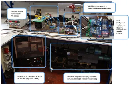
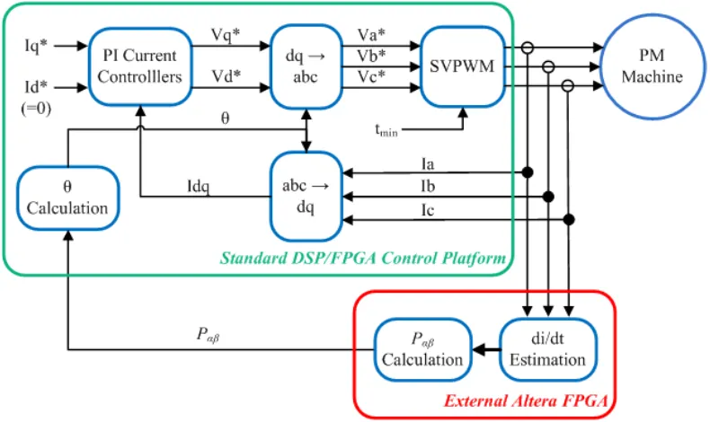
Before presenting experimental results, a brief description of the experimental system is given. The experimental system consists of a permanent magnet (PM) motor drive coupled to a DC machine and commercial DC drive which provides loading. The PM drive consists of a two level voltage source inverter and 3.82kW surface mounted permanent magnet machine controlled by a DSP/FPGA platform. A shaft mounted encoder provides the rotor position measurement used to control the motor.
The proposed ANN derivative estimation technique is implemented on a separate FPGA which samples the first 2μs of the PM motor phase current waveforms following inverter switching at a rate of 62.5 MSPS. The sampled current transients are then supplied to an ANN implemented on-board the FPGA and an estimate of the derivative is given.
used to calculate a position vector (Pαβ) and analyse the saturation saliency component. Fig. 1
[image:4.595.71.522.107.405.2]illustrates the experimental system.
Fig. 1: The experimental system used to evaluate the ANN derivative estimation technique
Experimental Results
Open Loop Testing
Initially results are presented which demonstrate that the ANN can estimate the derivative of any vector required for position estimation (first null, first active, second active or second null) in the PWM waveform to a reasonable accuracy. To facilitate this, the PM machine was operated as a normal closed loop vector controlled drive, obtaining a position measurement from a shaft mounted encoder. The estimated quantities were not used to control the motor (hence this testing is referred to as open loop). A 17µs minimum pulse width was applied to the PWM vectors allowing measurements from the Rogowski coil and 2IS method to be taken for comparison. The speed and load were set to values used when capturing ANN training data (30Hz, 83% load) to demonstrate the behaviour at what should be a good operating point. Fig. 2 (a)-(d) show the derivative estimates for each of the PWM vectors where one fundamental period is represented by 167 samples on the x-axis.
(c) Second Active Vector (d) Second Null Vector
Fig. 2: Derivatives measured from a derivative sensor, 2IS method and estimated by the ANN method for each of the PWM vectors in a PWM period
The results visibly show that a good derivative estimate is provided by the ANN for each of the PWM vectors at a given operating point. The increased errors of the “Second” vectors in Fig. 2 c) and d) (compared to the “First” vectors of a) and b)) are thought to be due to decaying current transient effects from the previously applied vectors which superimpose onto the high frequency current response due to the present switching event.
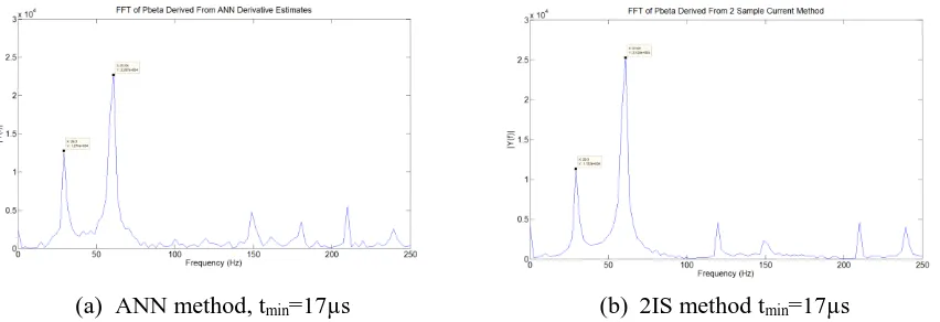
The derivative estimates in Fig. 2 allow a position vector (Pαβ) to be formulated which
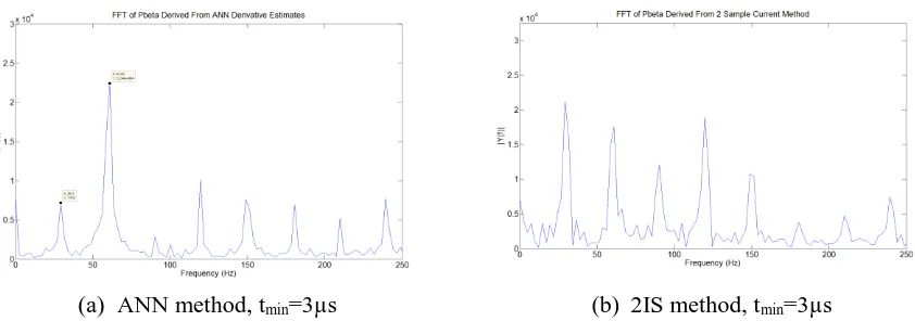
contains position information from the saturation saliency component. Fig. 3 shows an FFT of the β component of the position vectors obtained using derivatives from the ANN and 2IS methods allowing a comparison to be made (the saturation saliency component in this case lies at 60Hz (2fe where
fe=30Hz)). At the large pulse width condition stipulated (17µs) the 2IS method is expected to identify
the saturation saliency well. The ANN based result is clearly very similar the 2IS result.
(a) ANN method, tmin=17µs (b) 2IS method tmin=17µs
Fig. 3: FFT of the β component of position vectors derived using derivative estimates from the ANN and 2IS methods
[image:5.595.94.520.421.567.2]a) ANN Method a) 2IS Method
c) Comparison of methods Fixed Load (50%), Varying Speed
[image:6.595.76.530.68.389.2]d) Comparison of methods Fixed Speed (20Hz), Varying Load
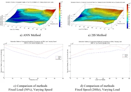
Fig. 4: Surface plots illustrating how variations in speed and load affect the saturation saliency
component. The ANN based method shows similar behaviour to the two current sample method. Cross sections of the surface plots are also shown in c) and d) to allow direct comparisons to be made.
With the ANN method proven to be capable of producing derivative estimates which were comparable to those from the 2IS method and could be used to identify the saturation saliency
component, investigations took place into the ability of the ANN to estimate derivatives when narrow PWM pulse widths were applied. With a minimum pulse width value of 3µs applied it was expected that the derivatives obtained should be similar to the 17µs case. Fig. 5 shows a comparison between the 3µs and 17µs cases for each PWM vector. It was not possible to use the Rogowski coils or 2IS methods as performance evaluators at this pulse width due to the errors introduced into the results by the high frequency oscillations.
(c) Second Active Vector (d) Second Null Vector
Fig. 5: A comparison of the derivatives estimated by the ANN method for each of the PWM vectors in a PWM period when operating with a 3µs and 17µs minimum pulse width.
The results shown demonstrate that the ANN can estimate derivatives for each of the PWM vectors to a reasonable accuracy when a narrow pulse width is applied. Once again, it was expected that the results obtained for the second active and second null vector would be the least accurate as the current measurements used to obtain these were likely to be affected by the decaying high frequency transient from the previous PWM vector. The errors in Fig. 5 (d) (second null vector) are thought to be due to this. Such influences cannot be included in the ANN training process due to the need to have long pulse widths to measure the derivative using conventional methods (derivative sensor, 2IS) for training. With a 3µs minimum pulse width applied the derivative results from the ANN method and the two current sample method were used to calculate a position vector. An FFT was performed on the
β component and the results are illustrated in Fig. 6. These results highlight the improvement that can be achieved using the proposed ANN based technique.
(a) ANN method, tmin=3µs (b) 2IS method, tmin=3µs
Fig. 6: FFT of the β component of position vectors derived using derivative estimates from the ANN and 2IS methods when a 3µs minimum pulse width is applied.
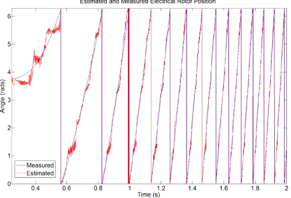
Finally the position vector can be used to provide an estimate of the rotor position by taking the arctangent of (Pβ/Pα). Synchronous filtering [11] was used to remove unwanted saliency
[image:7.595.95.516.433.581.2]Fig. 7: A comparison of the estimated and measured electrical angle with the machine being operated at 30Hz, under 70 % load (an untrained condition of the ANN).
Closed Loop Testing
An application area that has been identified for the proposed technique is the starting of heavy industrial drives which rely on mathematical model based sensorless control under normal medium to high speed operation. Such applications typically require a special staring procedure (owing to the inability of mathematical techniques to operate satisfactorily at low speed). A controlled application of torque is also desirable and preferable to a start under VF control. Following successful open loop tests the PM machine was configured to operate in torque control mode by disabling the speed control loop. The rotor position estimate from the ANN method would now be used for stationary frame (αβ) to rotating frame (dq) transformations rather than the measured value from the encoder. A control block diagram illustrating the setup is given in Fig. 8.
[image:8.595.101.496.473.708.2]The torque current demand value (Iq*) was initially set to zero and then increased (in increments of 0.25A with each current being applied for 0.5s) up to 15% of Iqrated to accelerate the
machine from standstill. This Iq* value was found to give satisfactory acceleration through trial and error. Once 15% Iqrated had been reached and applied for 0.5s, Iq* was set back to zero. Fig. 9 (a)
shows the estimated and measured rotor position. The accuracy of the estimated angle during the initial acceleration was poor. This was partly because a large minimum pulse width was being used to allow two current sample measurements to be recorded for comparison. The effects of a large
minimum pulse width are most noticeable at low speed. Another contributing factor is the large number of harmonic components present in the position vector (Pαβ) in addition to the second
harmonic component. The conventional synchronous filtering and mechanical model methods applied only offered limited success in cancelling undesirable harmonic components, especially during speed transients. As the speed increases the estimated angle settles and shows a good agreement with the measured value. The rotor speed measured from the encoder is also shown in Fig. 9 (b) for
completeness. The result shows a smooth and steady increase in rotor speed from standstill.
a) Estimated and measured electrical angle
[image:9.595.152.439.266.461.2]b) Mechanical rotor speed measured from the shaft mounted encoder
Conclusions
This paper has presented a new method capable of estimating current derivatives using phase current measurements affected by high frequency oscillations obtained using a standard industrial current sensor. The effectiveness of the technique has been demonstrated in a real-time experimental environment. Under long PWM pulse widths the ANN derivative estimates are comparable to those obtained from a Rogowski coil and 2IS methods. The estimated derivatives can be used to successfully identify the saturation saliency component in the face of variations in shaft speed and loading.
The advantage of the ANN method lies in its ability to estimate derivatives under narrow pulse widths. The derivative estimates obtained from the ANN with a 3μs minimum pulse width applied were shown to be very similar to those obtained when a 17μs minimum pulse width was applied. On the other hand, a reasonable derivative measurement could not be obtained from the Rogowski coil or 2IS method when a 3μs pulse width was applied. It was shown that the saturation saliency component could still be accurately identified under a 3μs minimum pulse width using the ANN method, while this was not possible using the 2IS method. Results showing the estimated rotor position estimation reveal a good agreement with the measured encoder value.
Finally the estimated rotor position was used to produce a torque controlled start of the PM machine from standstill. The encoder derived speed showed that a smooth acceleration was achieved. It is thought that improvements to the signal processing techniques applied to extract the saturation saliency component from the position vector could yield further improvements in performance. Full closed loop speed control achieved using the estimated rotor position and speed will be presented in a future publication.
References
[1] H. Yahan, et al., "Sensorless Control of Surface Mounted Permanent Magnetic Machine Using the Standard Space Vector PWN," in Industry Applications Conference, 2007. 42nd IAS Annual Meeting. Conference Record of the 2007 IEEE, 2007, pp. 661-667.
[2] Q. Gao, et al., "Sensorless Control of Induction Machines, including Zero Frequency using only Fundamental PWM Excitation," in IEEE Industrial Electronics, IECON 2006 - 32nd Annual Conference on, 2006, pp. 793-798.
[3] J. Juliet and J. Holtz, "Sensorless acquisition of the rotor position angle for induction motors with arbitrary stator windings," in Industry Applications Conference, 2004. 39th IAS Annual Meeting. Conference Record of the 2004 IEEE, 2004, pp. 1321-1328 vol.2.
[4] P. Nussbaumer and T. M. Wolbank, "Saliency tracking based sensorless control of AC machines exploiting inverter switching transients," in Sensorless Control for Electrical Drives (SLED), 2010 First Symposium on, 2010, pp. 114-119.
[5] Y. Hua, et al., "Improved sensorless control of a permanent magnet machine using fundamental pulse width modulation excitation," Electric Power Applications, IET, vol. 5, pp. 359-370, 2011.
[6] P. Nussbaumer and T. M. Wolbank, "Using oversampling techniques to extract ac machine saliency information," in IECON 2010 - 36th Annual Conference on IEEE Industrial Electronics Society, 2010, pp. 1035-1040.
[7] P. Nussbaumer and T. M. Wolbank, "Using switching transients to exploit sensorless control information for electric machines," in Sensorless Control for Electrical Drives (SLED), 2011 Symposium on, 2011, pp. 35-40.
[8] D. Yu and M. Sumner, "A novel current derivative measurement using recursive least square algorithms for sensorless control of permanent magnet synchronous machine," in Power Electronics and Motion Control Conference (IPEMC), 2012 7th International, 2012, pp. 1193-1200.
[9] LEM, "Current Transducer LA 25-P Datasheet."
[10] D. Hind, et al., "Use of an artificial neural network for current derivative estimation," in Power Electronics and Applications (EPE), 2013 15th European Conference on, 2013, pp. 1-10.