Towards understanding the cutting and fracture
mechanism in ceramic matrix composites
O. Gavalda Diaza, D.A. Axintea,∗
aRolls-Royce University Technology Centre in Manufacturing and On-Wing Technology, Faculty of Engineering, University of Nottingham, NG7 2RD, UK
Abstract
Ceramic Matrix Composites (CMCs) are increasingly used for the
mafacture of high-value parts for several industries such as the aerospace,
nu-clear and automotive. Nevertheless, their heterogenic, anisotropic and
brit-tle nature make difficult to characterise the machining process and
there-fore, an in-depth understanding of the cutting mechanics is needed. In this
regard, this paper aims to understand the different behaviours of CMCs
while employing orthogonal cutting. The first part of this article proposes
a novel theoretical approach to explain the different types of cutting
be-haviours (fracture and shear cutting) based on the inelastic and orthotropic
properties of the CMC’s by using a high imaging system and measuring the
cutting forces. The second part aims to understand the cutting and fracture
mechanism by developing for the first time a specific analytical model for
each of the three main orthotropic orientations, defined by the three main
relative fibre orientations respect to the feed direction, which are found in
cutting of CMCs. This is approached by the calculation of the specific
cut-ting energy needed to fracture the CMC’s during cutcut-ting (energy release
rate, Gc) using fracture mechanics and cutting theories. This analytical
model has been successfully validated for a Carbon/Carbon composite with
the experimental data obtained for the brittle cutting and by introducing
the concept of a rising R-curve in cutting models. Moreover, comparing the
mode, it is observed that the material experiences an important change
in the energy release rate according to the brittle-to-semi-ductile
transi-tion occurring while reducing the depth of cut. Finally, a novel monitoring
method based on the vibrations of the sample has been found successful to
understand the type of crack formation appearing while cutting CMCs.
Keywords: Machining, Ceramic Matrix Composites, Orthogonal cutting,
Fracture mechanism, Crack formation
2015 MSC: 00-01, 99-00
1. Introduction
1.1. Ceramic Matrix Composites (CMCs)
Composite materials have increased in demand in many different
in-dustries because of their excellent mechanical characteristics such as the
strength-to-weight, stiffness-to-weight, corrosion and fatigue resistance.
Com-posites are formed from two or more materials, resulting in properties that
can not be achieved with monolithic materials. Commonly, one of the
ma-terials acts as a matrix and the other one as a reinforcement. The matrix
is in charge of spreading the stress to the fibres and protecting them from
external damages while providing the final shape of the component. On
the other hand, the reinforcement provides greater mechanical properties.
[1].
Depending on the type of reinforcement, composite materials are
clas-sified in particulate, flake and fibre composites [2]. Fibre composite can
also be classified as short or long fibres. Short fibres slightly increase the
properties of the matrix randomly in all directions, while long fibres highly
increase the properties in specific directions. In aerospace applications,
∗Corresponding author
long fibre composites are consistently used in order to reduce weight by just
having preferential directions with high mechanical properties.
Compos-ite materials can also be classified depending on the nature of the matrix:
Polymer Matrix Composites (PMCs), Metal Matrix Composites (MMCs)
and Ceramic Matrix Composites (CMCs) [1, 3]. PMCs are often refereed as
FRP (Fibre Reinforced Polymer) and have a polymeric matrix (i.e. Epoxy
or Phenolic) reinforced with brittle fibres (i.e. Carbon or Glass). These
materials are being chosen as a replacement of light metal alloys such as
those based on aluminium or titanium. MMCs are used for applications
requiring higher temperature in service than the PMCs and the most
com-mon structure are Boron or Silicon-Carbide fibres embedded in a metal
matrix (i.e. Titanium or Steel) [1].
Ceramic Matrix Composites have been the preferred candidate for the
replacement of some elevated temperature materials in the modern
indus-tries. In aerospace, CMCs have been introduced in gas turbine engines
as a replacement of some superalloys [4] and in rocket nozzles [5]. For
nuclear applications, CMCs are under consideration to be used as a
struc-tural material for fusion and fission reactors [6]. CMCs have also been
employed in frictional applications as braking systems in cars or aircrafts
[1]. The CMC’s success in extremes applications is due to their high
me-chanical and chemical performances at high temperature, such as fatigue
and oxidation resistance [4]. Moreover, compared to the monolithic
ceram-ics, the reinforcement in CMCs displays improved fracture toughness and
mechanical strength. A common CMC material used in a wide range of
industrial applications is the Carbon/Carbon (C/C) in which high strength
carbon fibres are embedded in a graphite matrix. This combination makes
the C/C an excellent candidate for ultra-high specific strength
applica-tions. Further reinforced ceramics found in the aerospace industry are the
a Silicon Carbide matrix which possesses better corrosion resistance than
Carbon [7]. Due to this growing demand on CMCs, fundamental
orthog-onal cutting tests are needed for a better understanding of the machining
process.
1.2. Orthogonal cutting in composite materials
In so-called orthogonal cutting, a single cutting edge wider than the
work-piece is used to unidirectionally cut along the surface. The cutting is
assumed to be uniform along the cutting edge, reducing the problem into a
two-dimensional scenario [8]. The cutting mechanism in composite
materi-als has been analytically and experimentally investigated using orthogonal
cutting. Pwu and Hocheng [9] analysed the cut quality in unidirectional
composites by modelling the chip length and the fracture mechanism. The
model considered orthotropic behaviour and beam theories to understand
the chip formation but only considered fibres placed perpendicularly to
the cutting edge. Sahraie Jahromi and Bahr [10] proposed an analytical
model to calculate the cutting forces applying bending theories on single
fibres and extrapolating to the whole composite by using the fibre volume
fraction. Nevertheless, the model was only developed for one specific fibre
orientation with simulated results showing some discrepancies with some
experimental data. Bhatnagar et. al [11] correlated the cutting force with
the shear properties of composite materials for different fibre orientations
and proposed an empirical relation to calculate the cutting force. However,
the mechanics of the system were not modelled and therefore, the empirical
solution has limitations in model applicability for other types of composites
such as the CMCs. Wang and Zhang [12] studied the surface quality of
uni-directional composites by evaluating the influence of different rake angles
and fibre orientations; while this is useful information, the aspects of
cut were not considered. Moreover, several Finite Element Models (FEM)
using cohesive theories, elasto-plastic behaviour and fracture mechanisms
were studied to predict the cutting forces for different fibre orientations
[13, 14, 15]. While this work can provide useful specific data, an analytical
model might offer a better understanding of the parameters and materials
properties affecting the cutting mechanism.
Furthermore, all these models have been proposed for PMCs or MMCs
where a ductile cut formation is clearly predominant. In contrast with
these, in CMCs a transition between semi-ductile to brittle cutting can
often be found, affecting the surface damage created by the crack
prop-agation. In this respect, as the CMCs possess a brittle matrix, it could
be commented that considering its different mechanical behaviours under
cutting was a novel commitment necessary for the understanding of the
cutting process.
1.3. Fracture mechanics in cutting
Fracture mechanics has been used to some extent in orthogonal cutting
by considering the notion of fracture toughness for the understanding of
the crack generation [8, 16]. Patel et al. [17] and Wang et al. [18] used
orthogonal cutting as a method to calculate some materials properties such
as the fracture toughness and the yield stress in isotropic materials such
as metals and polymers. Liao and Axinte [19] used fracture mechanics to
predict the chip formation mechanism in cortical bones, also considered as
a composite structure. Nonetheless, the mechanical approach for the three
cutting orientations used (longitudinal, across and transverse) was
simpli-fied into one final analytical expression, loosing accuracy on the explanation
of the mechanical behaviour. Theoretical approaches for chip formation in
isotropic materials have been proposed to understand the bending and
However, due to the isotropy of the materials tested, an anisotropic
be-haviour on the fracture toughness and therefore of the cutting mechanism
was not considered.
Some researchers have been interested in the so-called ductile-to-brittle
transition that specially brittle materials can experience during the
ma-chining at relative low uncut chip thickness. It has been commented [21];
that, depending on the specific cutting energy, the machining can be
accom-plished by plastic deformation (ductile behaviour) or by crack propagation
(brittle behaviour). The comprehension of this transition point is a key
factor for the understanding of the material cracking and therefore, the
workpiece surface quality in machining brittle materials [22].
Neverthe-less, further research has not been documented in the interpretation of the
ductile-to-brittle transition between cutting modes in composites materials
such as CMCs where due to their brittle matrix, this phenomenon can occur
at low uncut chip thickness. Commonly CMCs are manufactured with long
reinforcing fibres creating three mutually perpendicular planes of material
symmetry. This implies that the elastic material properties are defined by
nine coefficients and therefore, CMCs are not completely anisotropic but
they are termed orthotropic [2].
In an attempt to fill the research gaps related to cutting orthotropic
materials that can display ductile-to-brittle behaviour, e.g CMCs, this
pa-per aims to propose a mechanism to interpret the cutting and fracture
behaviour for each of the three main orthotropic orientations. In this
re-spect, an analytical cutting model based on the inelastic behaviour and
fracture mechanics of orthotropic brittle composite materials is proposed
for the understanding of the surface quality and integrity in machining.
The model has been validated experimentally by analysing the machining
forces, cracks behaviour, vibrations and surface damages. This work might
process such as drilling, milling or turning for CMCs and similar materials.
2. Experimental methodology
To study the cutting mechanism in CMCs, orthogonal tests with
differ-ent fibre oridiffer-entations have been performed to observe the response of the
brittle matrix-composite and obtain unique data (e.g. forces, vibrations
and crack formation mechanisms) not previously found in the literature
and needed for the validation of the analytical approaches.
Samples (25 x 3 x 5 mm) of bidirectional Carbon-Carbon with an
ap-proximate Young Modulus along the fibre direction of 80 GPa and 5 GPa
out of the fibres direction, have been water-jet cut. Afterwards, the
sam-ples have been carefully polished to achieve the final dimensions and glued
with a structural epoxy resin to an aluminium plate in order to have greater
clamping surface and to avoid any induced damage in the composite
struc-ture.
An in-house developed 4-axis miniature machine tool [23], with a
re-peatability of 0.1µm of the positioning stage, was adapted for performing
orthogonal cutting tests. A solid carbide cutting edge with rake angleα=8◦,
clearance angle γ=8◦ and edge radius r=5µm was used as previously done
in [19]. In order to reduce the friction force and therefore to meet the setup
recommended for orthogonal cutting, the width of the sample was thinner
than the width of the cutting edge (2 mm). The cutting speed chosen for
the trials was 30 mm/min since this allowed to work with higher depths of
cut and easily understand the cutting mechanism. The cutting forces were
measured with a 3-component miniature dynamometer (Kistler 9317B) at
an acquisition rate of 10 kHz and the vibrations with a compact single
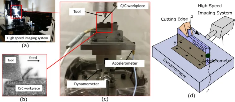
axe accelerometer PCB 352C23 from Piezotronics (Fig.1b, 1c). After the
cutting trials, the machined surfaces were analysed by Scanning Electron
x z
y
High Speed Imaging System
Dynamomet
er
Accelerometer Cutting Edge
Sample (a)
[image:8.595.108.488.109.274.2](b) (c) (d)
Figure 1: Orthogonal cutting set-up (a) general view of the high speed imaging system (b) view from the high imaging system (c) close-up of the cutting zone (d) scheme of the set-up
To understand the crack behaviour, a High Speed Camera Y4-S2-M
and an objective K2 CF-4 with a long distance high magnification lens (K2
infinity video lens) was used (Fig.1a). The cutting process was recorded
at a resolution of 1024x1024 and a recording speed of 1000 fps. In order
to explain the cutting mechanism observed and to get the data needed for
the analytical approaches, the video was synchronised with the force and
vibration signals.
3. Ductile-to-brittle transition in cutting CMCs
CMCs are commonly formed by a ceramic matrix reinforced with
bidi-rectional fibres. Nevertheless, analysing the composite at a local area (as
the situation encountered during the cutting process at a typical chip
thick-ness) the composite structure can be simplified as a unidirectional. In the
case where the depth of cut is higher than the thickness of a unidirectional
ply the tool faces an environment with bidirectional fibres which can be
studied as two unidirectional cases. Based on the different shear
mecha-nisms (elastic and inelastic [24]) that CMCs experience depending on the
behaviours has been developed. Therefore, this study considers three main
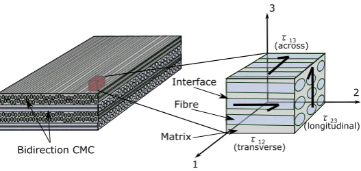
scenarios related to the cutting direction and the shear stresses:
longitudi-nal, across and transverse fibres (see Fig.2).
1
2 3
Fibre
Matrix Interface
Bidirection CMC
τ23 (longitudinal) τ12
(transverse)
[image:9.595.167.431.175.300.2]τ13 (across)
Figure 2: Schematic on a bidirectional structure of a CMC with a close-up showing the main directions of shear stress
Compared to monolithic ceramics that possess mostly a linear shear
behaviour, the inelastic and hence bilinear behaviour of CMC’s plays an
important role in defining the machining modes. The shear through the
fibres involves two main mechanisms: matrix failure and fibre failure [25].
For small shear stresses (τ < τM CScomp), fibres and matrix resist with a higher
shear modulus (Gcomp), while when the stress reaches the critical value
(Matrix Shear Strength, τM CScomp) the matrix fails debonding from the fibres
and only the fibres resists against the shear stress with a lower shear
mod-ulus (Gf ibres), as shown in Fig.3. The material is completely sheared at
a stress higher than the Ultimate Shear Strength (τU SScomp). This difference
in shear behaviour between monolithic and reinforced ceramics is useful
to explain the different cutting modes appearing in the cutting of CMCs
depending on the fibre orientation.
3.1. Cutting along longitudinal fibres
The cutting process along longitudinal fibres can be considered in three
cutting modes: (i) composite shear; (ii) matrix shear; and (iii) matrix
strain stress
γ
USScompγ
MSScompγ
USSmonG
fibresG
comp [image:10.595.187.409.107.250.2]Reinforced ceramic Monolithic ceramic USS: Ultimate Shear Strength MSS: Matrix Shear Strength
Figure 3: Linear and bilinear shear behaviour of monolithic and reinforced brittle ma-terials (adapted from [11])
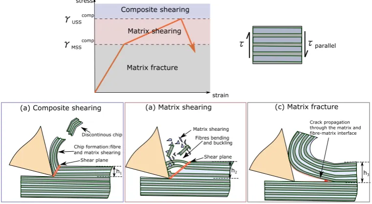
• (i) Composite shear: appears when the cutting shear stress is higher
than the ultimate shear strength (τU SScomp) of the whole CMC. In this
case, the material is cut in a shear mode and pull out as a form of
discontinuous chips due to the heterogeneity and fragile nature of the
chips (See Fig.4a).
• (ii) Matrix shear: appears when the shear stress applied is lower than
the ultimate shear strength (τU SScomp) but higher than the matrix shear
strength (τM SScomp). This condition is unique for cutting composites
with longitudinal fibres since the shear plane is formed through the
fibres. In this case, the material is cut by a combination of matrix
debonding due to the shear and bending or buckling of the fibres due
to the movement of the tool (See Fig.4b).
• (iii) Matrix fracture: appears when the shear stress applied does not
reach the matrix shear strength (τM SScomp) and therefore, the material
cannot be sheared. Instead, the material is fractured (in a brittle
mode) by crack propagation in the cutting plane. Since the lowest
fracture toughness of the composite material is found in interface
between the fibres and the matrix, the crack propagates through this
toughness, the crack does not divert to the surface, creating a brittle
continuous offcut formation [8].
Shear plane Chip formation:fibre and matrix shearing Discontinous chip
Crack propagation through the matrix and fibre-matrix interface
h1 h2 h
3
Composite shearing
Matrix shearing
Matrix fracture
(a) Composite shearing (a) Matrix shearing (c) Matrix fracture
strain stress
γUSScomp
γMSScomp τ
parallel
[image:11.595.107.488.162.371.2]τ
Figure 4: Cutting modes in longitudinal fibres (a) composite shear (b) matrix shear (c) matrix fracture withh1< h2< h3
As previously stated in the literature, the main characteristics of the
material behaviours in orthogonal cutting could be revealed by studying the
uncut chip thickness. Therefore, orthogonal cutting tests were performed
to empirically validate the cutting modes at different chip thickness (from
5µm until 170µm) keeping a constant width of cut of 1mm. Frames from
the high speed imaging system have been used to capture the materials
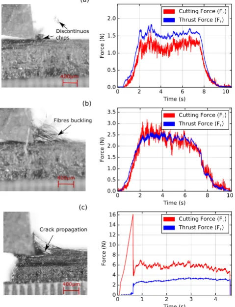
behaviour and correlated to the cutting forces signals in Fig.5. As shown
in Fig.5a for the composite shearing mode, the material is removed in the
form of discontinuous chips, shearing both fibres and matrix which yields
steady forces in the cutting and thrust direction. In the case of the matrix
shearing mode (Fig.5b) the fibres cannot be sheared and they are clearly
bent and buckled; as the cutting is stable and continuous the cutting forces
are also constant. Finally, in the case of matrix fracture (Fig.5c) a big peak
in the cutting force is found during the first contact of the tool with the
constant at a lower value since the crack is steadily propagated due to a
peeling-up action of the fibres from the matrix.
0 1 2 3 4
Time (s) 0
2 4 6 8 10 12 14 16
Force (N)
Cutting Force (Fc)
Thrust Force (Ft)
(c) 0 2 4Time (s)6 8 10
0.0 0.5 1.0 1.5 2.0 2.5 3.0 3.5
Force (N)
Cutting Force (Fc)
Thrust Force (Ft) (b)
0 2 4 6 8 10
Time (s) 0.0
0.5 1.0 1.5 2.0
Force (N)
Cutting Force (Fc)
[image:12.595.186.426.167.481.2]Thrust Force (Ft) (a)
Figure 5: Frames showing the cutting mechanism and the forces in longitudinal fibres
for (a) composite shearing (h=5 µm), (b) matrix shearing (h=30 µm) and (c) matrix
fracture (h=170µm)
3.2. Cutting along across fibres
The cutting process of across fibres has been segregated in two cutting
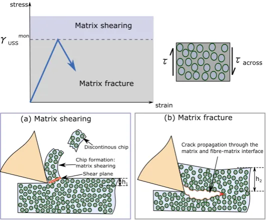
modes: (i) matrix shearing and (ii) matrix fracture. In this scenario, the
shear plane evades to be generated through the fibres choosing a lower
energy path through the matrix and interfaces. This indicates that the
material does not experience an inelastic behaviour and it just behave as a
monolithic ceramic possessing a critical strength τmon
• (i) Matrix shearing: appears when the shear stress applied is higher
than the ultimate shear strength (τmon
U SS) of the matrix. In this respect,
the material can be removed by a linear shear mode characteristic of
monolithic ceramics (See Fig.6a).
• (ii) Matrix fracture: appears when the shear stress applied does not
reach the ultimate shear strength (τmon
U SS) thus the composite is
re-moved by fracture. Firstly, the crack propagates in the cutting plane
and it finally tends to rotate to the surface forming a discrete
off-cut (as previously described in the literature for an isotropic material
having a constant toughness in the orthogonal cutting plane [8]). As
explained for longitudinal fibres, the crack tends to propagate through
the interface between the fibre and the matrix (See Fig.6b).
Matrix shearing
Matrix fracture
(a) Matrix shearing (b) Matrix fracture
strain stress
γUSSmon
τacross
τ
Shear plane Chip formation: matrix shearing
Discontinous chip Crack propagation through the matrix and fibre-matrix interface
[image:13.595.165.433.387.607.2]h1 h2
Figure 6: Cutting modes in across fibres (a) matrix shear (b) matrix fracture with
h1< h2
As done for longitudinal fibres, the C/C has been orthogonally cut at
different uncut chip thickness (from 5µm until 150µm) keeping a constant
width of cut of 1mm to empirically observe the cutting modes. In Fig.7a the
chips and steady forces. On the other hand, Fig.7b shows the matrix
fracture, that due to the discontinuous chip formation, the cutting force
tends to suffer rapid drops to zero.
0 1 2 3 4
Time (s) 0.0
0.5 1.0 1.5 2.0 2.5 3.0 3.5
Force (N)
Cutting Force (Fc) Thrust Force (Ft)
(b)
0 1 2 3 4 5
Time (s) 0.0
0.5 1.0 1.5 2.0 2.5 3.0 3.5
Force (N)
Cutting Force (Fc) Thrust Force (Ft)
[image:14.595.173.445.184.433.2](a)
Figure 7: Frames showing the cutting mechanism and the forces in across fibres for (a)
matrix shearing (h=5µm) and (b) matrix fracture (h=110µm)
3.3. Cutting along transverse fibres
The cutting mechanism in transverse fibres can also be explained in two
cutting modes: matrix sharing (i) and matrix fracture (ii).
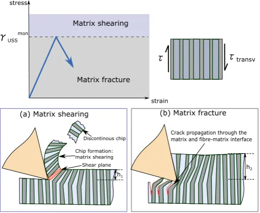
• (i) Matrix shearing: the same principle applied for the across
orienta-tions is found for transverse fibres. If the cutting shear stress is higher
than the ultimate shear strength of the matrix (τmon
U SS) the material
can be removed by shear cutting. The shear plane is formed along
the matrix avoiding the fibres and therefore, minimising the cutting
energy (see Fig.8a). As observed for across fibres, in transverse fibres
the composite acts as a monolithic ceramic and in this case the fibres
• (ii) Matrix fracture: appears when the shear stress applied does not
reach the ultimate shear strength (τmon
U SS). In the case of transverse
fibres, the fibre-matrix interface is found along the vertical direction,
hence the crack formation also appears along this axis (See Fig.8b).
Therefore, the brittle offcut cannot be classified in any type previously
found in the literature, since the material is not removed by crack
propagation in the cutting plane but by brittle bending along the
vertical axis.
Matrix shearing
Matrix fracture
(a) Matrix shearing (b) Matrix fracture
strain stress
γUSSmon
τtransv τ
Shear plane Chip formation: matrix shearing
Discontinous chip Crack propagation through the matrix and fibre-matrix interface
h2
[image:15.595.165.432.295.514.2]h1
Figure 8: Cutting modes in transverse fibres (a) composite shear (b) composite fracture withh1< h2
Orthogonal cutting test have been performed for transverse fibres at
different uncut chip thickness (from 5µm until 120µm) keeping a width of
cut of 0.2 mm. In Fig.9a a discontinuous chip formation has been recorded
with the camera causing steady forces. In Fig.9b the frame shows how
the region being bent accumulates damages (darker zone) due to the crack
propagation. In this case, since the cut is continuous, the forces do not
have big drops in value.
under-0 2 4 6 8 Time (s)
0.0 0.5 1.0 1.5 2.0 2.5 3.0 3.5
Force (N)
Cutting Force (Fc) Thrust Force (Ft)
(b) 0 1 2 3 4 5 6 7 8Time (s)
0.0 0.2 0.4 0.6 0.8 1.0 1.2 1.4
Force (N)
Cutting Force (Fc) Thrust Force (Ft)
[image:16.595.173.446.114.367.2](a)
Figure 9: Frames showing the cutting mechanism and the forces in transverse fibres for
(a) matrix shearing (h=5µm) and (b) matrix fracture (h=100µm)
standing of the brittle and shearing domains has been done by analytically
modelling the energy release rate.
4. Modelling the brittle regime: fracture cutting of CMCs
As previously shown, when the depth of cut is increased, the material
tends to fracture along the fibre-matrix interface in an elastic domain.
Hence, this section proposes a novel analytical approach to facilitate the
understanding of the fracture cutting in orthotropic brittle materials by
calculating the energy release rate based on the mechanism found, for the
three orientations, in the experimental section.
As previously validated in the literature, beam theory can be used to
understand orthogonal cutting [26, 16]. Several authors [19] agreed than
in orthogonal cutting the crack propagation is a combination of Mode I
experi-mental section it is postulated that this approach might not be accurate for
orthotropic materials and depending of the fibre orientations the cracking
mode might vary.
As the material is being removed in a brittle mode, the work applied
by the external forces is transferred to the material in the form of elastic
strain energy (U) and potential energy for the fracture (Π):
Wexternal f orces=U + Π (1)
Assuming that the crack occurs in a load controlled mode [27]:
Wexternal f orces= 2U (2)
Therefore, the specific cutting energy available for the crack to
propa-gate (G) can be related to the elastic strain energy as:
G= dΠ dA =
1 w
dU(a)
da (3)
Where w is the width of the cut and a is the crack length.
The fracturing mode occurs if the specific energy (G) applied to the
crack zone is higher than the threshold called energy release rate or fracture
energy (Gc) [27].
G≥Gc (4)
As aforementioned, an accurate model needs to explain each of the
cut-ting conditions separately, therefore three different approaches have been
developed to explain the three main orthotropic conditions in which cutting
4.1. Fracture cutting along longitudinal fibres
Continuous chip formation occurs during the fracture cutting through
longitudinal fibres and, for that reason two different fracture scenarios could
appear while cutting. The first fracture mechanism arises during the first
contact of the cutting tool with the material (tool indentation). The second
one appears once the main crack has been formed (peeling-up action).
4.1.1. Tool indentation
Before the cutting edge indents the material, the tool faces a situation
where the material needs to be initially cracked. Consequently, the tool
applies an axial compressive stress with no thrust force (as shown in Fig.5c).
As shown in Fig.10a, the compressive stress causes a deformation (∆1)
of the material. The elastic energy density (U) in compression can be
calculated as:
(a)
(b) Mode II
Mode I
Beam Scheme
Fc Δ1
a z
x
Fc Ft
a0 a
z Fc
[image:18.595.125.461.407.568.2]Fc Ft
Figure 10: Mechanical approach for the fracture cutting of longitudinal fibres during the (a) tool indentation and (b) peel-up action
δU = σ
2
x 2Ex
= F
2
c 2Ex(wh)2
(5)
Where Ex is the Young Modulus along the fibre axis, Fc is the cutting
force, w the width of the sample and h the depth of cut.
U =
Z a
0
δU dV = F
2
ca 2Exwh
(6)
Where a is the crack length formed during the indentation process.
Once the elastic energy is calculated, using Eq.3 the specific energy
available for crack propagation can be written as:
G= F
2
c 2Exw2h
(7)
During the tool indentation, the thrust force is zero or negligible
com-pared to the cutting force (See Fig.5c). Hence, the energy release rate
acting during the tool indentation is due to a shearing mode (mode II).
As aforementioned in Eq.4, the crack is able to form and propagate if the
specific energy is equal or higher than the energy release rate. Eq.8 can
therefore calculate the energy release rate during the tool indentation
pro-cess:
G≥GIIc →GIIc = F
2
c 2Exw2h
(8)
4.1.2. Peeling-up action
Due to the continuous chip formation, the chip is not removed and the
crack only propagates along the cutting plane, therefore the tool rake face
pushes the material, as shown in Fig.10b.
The chip is exposed to a bending force caused by the cutting (Fc) and
thrust force (Ft). The elastic energy density of a bending beam can be
calculated as:
δU = M
2
2ExI
= (Fcz−Ftx)
2
2ExI
(9)
Where I is the moment of inertia (I = wh3/12) and x and z are the
strain energy is:
U =
Z a0+a
0
δU dx= (Fcz−Ft(a0+a))
3
6ExIFc
(10)
Where a0 is the main crack formed during the indentation and a is the
stable crack happened during the peeling-up action. Nevertheless, due to
the continuous chip formation appearing in the brittle cutting of
longitudi-nal fibres, friction between the rake face and the chip should be considered.
Therefore the trust and cutting forces contributing to the elastic bending
can be calculated as:
Fc0 =Fc−N µsin(α) =Fc−(Fccos(α)−Ftsin(α))µsin(α)
Ft0 =Ft−N µcos(α) = Ft−(Fccos(α)−Ftsin(α))µcos(α)
(11)
where µ is the friction coefficient and the α is the rake angle. An
approximated value of µ has been extracted from the literature for the
cutting of quasi-isotropic carbon reinforced composite, containing fibres in
different directions. [28].
In the case of the peeling up action, the crack propagates due to an
opening mode (see Fig.10b). Hence, the energy release rate in mode I
dominates the peeling-up mechanism and can be calculated as:
GIc = 6(F
0
cz−F
0
t(a0+a))2
Exw2h3
(12)
Therefore, Eq.8 and Eq.12 define the specific energy needed to fracture
the material while cutting along longitudinal fibres.
4.2. Fracture cutting along across fibres
A discrete chip is formed during the brittle elastic cutting of across
(Mode II) on the cutting plane, similarly as found for the tool indentation
mechanism in longitudinal fibres (See Fig.11). This hypothesis can again
be validated from the force diagram in Fig.7b, where the trust force is null
during the crack formation. Hence, the energy release rate in shear mode
(GII
c ) causes the crack to propagate during the cutting of across fibres and
can be calculated as:
GIIc = F
2
c 2Exw2h
(13)
Where in this case the Young modulus in the cutting direction (Ex)
correspond to the one out of axis.
z
x Fc
Mode II Beam Scheme
Fc Δ1
[image:21.595.145.453.344.424.2]a
Figure 11: Mechanical approach for the fracture cutting of across fibres
4.3. Fracture cutting along transverse fibres
As previously stated, in cutting transverse fibres the composite suffers
a brittle behaviour due to the elastic bending along the axis of the fibres
caused by the bending force (see Fig.12).
Mode I Fc
Ft
ac
Beam Scheme
z
x
Fc
Ft
δ
[image:21.595.144.449.583.702.2]The bending force is caused by the cutting (Fc) and the thrust (Ft)
forces as shown in Fig.12. As previously explained, the elastic strain
en-ergy can be calculated integrating the elastic enen-ergy density obtained for
bending:
U =
Z a0+a
0
δU dx= (Fca+Ftx)
3
6EzIFc
(14)
In this case, the section of the beam is given by the width of the sample
(w) and by the bending length (b). The bending length depends on the
material voids such as the porosities and flaws, highly found in CMC due
to the manufacturing process.
The maximum deflection (δmax) of the central axis shown in Fig.12 can
be calculated using beam theories for a cantilever beam with a force applied
at a distance h from the edge:
δmax = Fca2 6EzI
(3(a+h)−a) (15)
Therefore as shown in Fig.13 an average bending distance (b) can be
calculated assuming a constant distribution of voids (p):
b =δmax/p (16)
Considering that the crack propagates between each Representative
El-ementary Volume (REV), the energy release rate in opening mode for
trans-verse fibres can be calculated as:
G= 6(Fca+Ftδmax)
2
Ezw2b3
b LREV
(17)
WhereLREV is the width of a single REV, as shown in Fig13. From the
high imaging system, it can be assumed that: Fca Ftδmax. Therefore,
(a) (b)
Representative elementary volume (REV): fibre + interface + matrix
Porosity and flaws
(assuming a constant distribution) Fc
[image:23.595.157.448.109.244.2]Bending length (b) LREV
Figure 13: Structure of a CMC considering a constant distribution of porosities and flaws (a) before bending (b) after bending
GIc = 6(Fca)
2
Ezw2b3 b LREV
(18)
Once the fracture cutting has been explained, an analytical study of
the shear cutting has also been proposed.
5. Modelling the semi-ductile regime: shear cutting of CMCs
In this case the material is being removed by shear, therefore the work
done by the external forces is transferred to the material within the form of
shear strain energy, energy dissipation due to friction and potential energy
for fracture:
Wexternal f orces=Ushear+Ef riction+ Π (19)
The fracture energy available is applied to the cutting path when the
two surfaces of the material are separated by the tool:
Fcdδx =
Z
τ(γ)dγdV +Ef ric,α+Ef ric,β +Gwda (20)
Where R
τ(γ)dγ represents the linear/bilinear shear energy stored by
the CMC,dδx represents the tool displacement in the cutting direction and
mode, the crack distance ’da’ can be related to the movement of the tool,
therefore it can be assumed that da=dδx [8]. Ef ric,α and Ef ric,β represent
the friction energy dissipated in the rake and clearance face respectively.
The friction forces in both faces can then be expressed as:
Ff ric,α =µ(Fccos(α)−Ftsin(α))
Ff ric,β =µ(Ftcos(β)−Fcsin(β))
(21)
Therefore, Eq20 can be rewritten as:
Fc=τ γhw+Ff ric,αcos(α) +Ff ric,βcos(β) +Gw (22)
Where shear strain (γ) in shear cutting can be written as [8]:
γ =cot(φ) +tan(φ−α) (23)
Combining Eq.22 and Eq.23 an isolating the energy release rate in shear:
G= Fc w −
Ff ric,α
w cos(α)− Ff ric,β
w cos(β)−τ U SS
i h(cot(φ) +tan(φ−α)) (24)
Therefore, the energy release rate in a semi-ductile mode can be
calcu-lated using Eq.24. As previously stated and as shown in Fig.14 the shear
behaviour (τU SS
i ) depends on the fibre orientation. Moreover, in shear
cutting, interlaminar and translaminar fracture toughness appear for the
Bilinear shear stress behavior
Interlaminar fracture toughness
Linear shear stress behavior
Interlaminar fracture toughness
Linear shear stress behavior
Translaminar fracture toughness
[image:25.595.110.488.112.197.2](a) (b) (c)
Figure 14: Shear cutting approach for (a) longitudinal fibres (b) across fibres (c) trans-verse fibres
6. Results and discussion relating the proposed models with the
experimental trials
6.1. Energy release rate in brittle cutting
6.1.1. Longitudinal fibres
The forces in Fig.15 show a clear difference between the two cutting
stages previously explained: tool indentation and peel-up action. For the
tool indentation, Eq.8 is used to find theGII
c,long during the first force peak.
During the stable cutting, the peel-up action occurs and the energy release
rate in mode I can be calculated by using Eq.12. Employing a tracking
soft-ware to the images obtained from the high speed camera, an approximate
and quantitative average distances have been estimated (a+a0 ≈ 500µm
and z ≈ 500µm) for the calculation of GI
c,long. The vibration signal in
Fig.15a confirm our hypothesis by showing that during the indentation,
the tool suffers a big acceleration due to a first unstable crack propagation.
Nevertheless, during the peel-up action the crack is propagated stably and
therefore the tool does not suffer high vibrations.
6.1.2. Across fibres
The energy release rate in cutting across fibres is dominated by a crack
propagation in mode II (GII
c,across) and can be obtained using Eq.13. The
energy release rate needs to be calculated for the individual peaks
0 1 2 3 4 Time (s) 15 10 5 0 5 10 15 Fo rc e ( N) 150 100 50 0 50 100 150 Vi b ra tio n (m/ s 2)
Cutting Force (Fc)
Thrust Force (Ft)
Vibration
400μm 400μm
(a) (b) (c)
Compression applied by the tool rake face
a
Main crack formed due to the tool indentation
Fc
Peel-up mechanism: stable propagation of the crack
400μm Fc
Ft Ff
a
[image:26.595.132.468.109.377.2]z
Figure 15: Forces and vibrations correlated with frames from the high speed camera for (a) first compression (b) tool indentation (c) peel-up action
signals in Fig.16 validate our assumptions stating that a discontinuous
of-fcut is formed and the tool suffers a vibration at each new impact with
the material. Compared to the acceleration of the tool happening for the
indentation in longitudinal fibres, the amplitude of the vibration in across
fibres is significantly lower since the Young Modulus along the fibres axis
is higher than the one out of the fibres axis. Nevertheless, the amplitude
in across fibres is longer on time, meaning that a longer crack is formed.
6.1.3. Transverse fibres
The energy release rate in cutting transverse fibres (GIc,trans) has been
calculated using Eq.18. An approximate value of crack length of a ≈ 500
µm(obtained from the tracking software and the images of the high speed
camera) has been considered. In this case, the crack is continuously formed
0 1 2 3 4 5 Time (s)
3 2 1 0 1 2 3
Fo
rc
e
(
N)
30 20 10 0 10 20 30
Vi
b
ra
tio
n
(m/
s
2)
Cutting Force (Fc)
Thrust Force (Ft)
Vibration
(a) (b) (c)
Compression applied
by the tool rake face Crack formation Crack propagation
a
Fc
[image:27.595.133.468.107.375.2]400μm 400μm 400μm
Figure 16: Forces and vibrations correlated with frames from the high speed camera for (a) first compression (b) crack formation (c) crack propagation
vibrations, as shown in Fig.17.
In the authors knowledge, previous research incorporating fracture
tough-ness in cutting has not considered that a great number of materials have
a non-constant energy release rate depending on the crack length (rising
R-curve) [27]. In the particular case of cutting, it is proved that the cracks
formed are small (between 5-500 µm), therefore the critical energy release
rate used for macroscopic tests should not be considered for the cutting
models. In the case of the interlaminar fracture toughness of the C/C, the
material possess a rising R-curve for mode I and II [29, 30]. The curves
for C/C have been digitized to obtain the values of energy release rate for
short cracks formation (between 200 and 500µm as observed from the high
speed system). Fig.18 show a comparison between the theoretical and
ex-perimental results for the energy release rate in mode I and II respectively.
0 2 4 6 8 Time (s) 3 2 1 0 1 2 3 Fo rc e ( N) 20 10 0 10 20 Vi b ra tio n (m/ s 2)
Cutting Force (Fc)
Thrust Force (Ft)
Vibration
400μm 400μm 400μm
Crack formation due to the bending moment
Fc
a
Crack propagation along the fibres
a
Constant damage through the cutting path
[image:28.595.132.469.107.362.2](a) (b) (c)
Figure 17: Forces and vibrations correlated with frames from the high speed camera for (a) first instance of bending (b) first crack formation (c) multiple cracks formed in the material
similar to the ones extracted from the rising R-curve (green). The only
case were more imprecise results were found was for the GI
c,long. This
er-ror might come due to the averaging of the different experimental values
(a+a0, y and µ) used for this specific cutting condition. Moreover, the
graph shows that the values obtained assuming a flat R-curve (red bands)
are significantly higher and therefore non appropriate for the validation of
the cutting model.
A SEM analysis has been performed to the machined surface after the
brittle cutting (see Fig.19). The results show that the damages found are
due to the crack propagation through the fibre axis. For this reason, in the
model validation the interlaminar fracture toughness of the Carbon/Carbon
0 20 40 60 80 100 120 140 160 Ene rg y re le a se r a te ( N/ m)
GIctheoretical GIclongitudinal fibres (GIc,long) GIctransverse fibres (GIc,trans) GIcassuming a flat R-Curve
0 20 40 60 80 100 120 140 160 Ene rg y re le a se r a te ( N/ m)
GIIctheoretical GII
clongitudinal fibres(GIIc,long)
GII
cacross fibres(GII c,across)
GII
cassuming a flat R-Curve
[image:29.595.145.484.131.306.2](a) (b)
Figure 18: Average results for the energy release rate in (a) Mode I: opening mode (b) Mode II: shear mode
across fibres
(c)
transverse fibres (a)
(b)
parallel fi
bres
Fibre pull-out Unpulled fibre
Interface between parallalel and across
Unpulled fibre
Bent/uncut fibres
Matrix fracture and removal width of cut
width of cut width of cut
[image:29.595.159.462.362.669.2]6.2. Energy release rate in semi-ductile cutting
The energy release rate in shear mode can be calculated using Eq.24. As
explained in the cutting modes section, in longitudinal fibres the ultimate
shear strength (τU SScomp) is higher than in across and transverse fibres (τmon U SS)
due to the inelastic behaviour. For longitudinal fibres an Ultimate Shear
Stress of ≈ 45 MPa has been found in the literature for a Carbon-Carbon
[25]. On the other hand, a shear strength of a monolithic graphite (≈16
MPa) has been used for across and transverse fibres [31]. Any effective
analytical expression has not been found in the literature to describe the
shear angle in cutting different fibres orientations. For this reason the
energy release rate for shear cutting has been evaluated for the whole range
of possible and common shear angles (10◦ < φ < 50◦).
From the results plotted in Fig.20, it is observed that the energy
re-lease rate for longitudinal and across fibres (green and blue respectively)
have a similar magnitude: Gc,long=457±109 N/m and Gc,across=558±39
N/m. On the other hand, while cutting transverse fibres, since the cutting
path needs to break the fibres, the energy release rate needed is greater
(Gc,transv=1161±78 N/m) and it is not any more the interlaminar but the
translaminar fracture toughness. It is then affirmed that the equation Eq.24
gives coherent results and it is applicable for cutting orthotropic materials
during shear cutting.
6.3. Comparison between the energy release rate in brittle and semi-ductile
regimes
A clear difference between the energy release rate for the fracture and
shear cutting modes has been found. In the case of brittle cutting an
ap-proximated 10 times lower G is needed for the crack to propagate through
the material. Therefore we can postulate that the Carbon/Carbon changes
obser-0 500 1000 1500
Ene
rg
y
re
le
a
se
r
a
te
(
N/
m)
G longitudinal fibres (Gc,long)
G across fibres (Gc,across)
G transverse fibres (Gc,transv)
Interlaminar energy release rate
[image:31.595.170.422.110.315.2]Translaminar energy release rate
Figure 20: Average results for the energy release rate in shear cutting for the three cutting orientations
vations have been found in other materials, where the fracture toughness
decreases when the material behaves more brittle due to a reduction of the
testing temperature [32].
7. Conclusion
Ceramic Matrix Composites start to be a material choice for
manufac-turing components for several high values industries (i.e. aerospace and
automotive) and therefore, an understanding of the mechanism by which
they are machined is a key factor. The aim of the paper is to put the basis
of the understanding on how the shear and fracture cutting mechanisms
appear in orthotropic brittle materials such as the CMCs. The main points
treated to achieve this goal are:
• An extensive experimental work in Carbon/Carbon has been
per-formed including the three main fibre orientation that define the
orthotropy of these materials: longitudinal, across and transverse.
have been theoretically explained based on the linear/bilinear
prop-erties of the CMCs in shearing conditions. Apart from a force sensor,
a high imaging system and a vibration sensor have been used to
un-derstand the shear and fracture mechanism. The most relevant data
acquired from these sensors has been used to explain the different
cut-ting behaviours proving a brittle to semi-ductile transition suffered
by CMCs.
• A novel analytical model for the brittle/fracture cutting has been
developed specifically for each of the three cutting orientations. The
analytical expression allows to calculate the energy release rate and
has been validated based on the rising R-curve that these composite
materials posses in a brittle fracture domain. This agreement between
the theoretical and experimental results confirm that the mechanism
has been accurately modelled understanding the cutting mechanics
for each of the three orientations.
• An analytical model for the shear cutting mode has been detailed
with the aim of calculating the energy release rate in a semi-ductile
mode. Positive results have been obtained for the different methods
distinguishing between interlaminar fracture toughness (happening in
longitudinal and across fibres) and translaminar fracture toughness
(appearing in transverse fibres).
• A novel explanation on the variation of the fracture toughness
be-tween cutting methods has been found in CMCs. As defined for
other fracture tests, the material can suffer from a ductile-to-brittle
transition that can highly affect the fracture properties such as the
energy release rate. This certitude might definitely need to be
con-sidered in future cutting models where the material suffer different
Acknowledgement
The authors gratefully acknowledge Rolls Royce Plc for the funding
support received during the work. A great thanks goes to Dr. Paul
Butler-Smith and Mr. Zhirong Liao from University of Nottingham for their
sup-port in this work.
References
[1] R. Teti. Machining of Composite Materials. CIRP Annals -
Manufac-turing Technology, 51(2):611–634, 2002.
[2] Autar K. Kaw. Mechanics of composite materials. Taylor & Francis, 2006.
[3] H. Hocheng. Machining technology for composite materials principles
and practice. Woodhead Pub, 2012.
[4] Patrick Spriet. CMC Applications to Gas Turbines. InCeramic
Ma-trix Composites, chapter 21, pages 591–608. John Wiley & Sons, Inc.,
Hoboken, NJ, USA, oct 2014.
[5] Walter Krenkel and Jacques Georges Th´ebault. Ceramic Matrix Com-posites for Friction Applications. InCeramic Matrix Composites, chap-ter 23, pages 647–671. John Wiley & Sons, Inc., Hoboken, NJ, USA, oct 2014.
[6] C´edric Sauder. Ceramic Matrix Composites: Nuclear Applications. In
Ceramic Matrix Composites, chapter 22, pages 609–646. John Wiley
& Sons, Inc., Hoboken, NJ, USA, oct 2014.
[7] Bernhard Heidenreich. C/SiC and C/C-SiC Composites. In Ceramic
Matrix Composites, chapter 6, pages 147–216. John Wiley & Sons,
Inc., Hoboken, NJ, USA, oct 2014.
[8] Tony Atkins. Chapter 3 Simple Orthogonal Cutting of Floppy, Brittle and Ductile Materials. In The Science and Engineering of Cutting, chapter 3, pages 35–74. 2009.
[10] A. Sahraie Jahromi and B. Bahr. An analytical method for predicting cutting forces in orthogonal machining of unidirectional composites.
Composites Science and Technology, 70(16):2290–2297, 2010.
[11] N. Bhatnagar, N. Ramakrishnan, N.K. Naik, and R. Komanduri. On the machining of fiber reinforced plastic (FRP) composite laminates.
International Journal of Machine Tools and Manufacture, 35(5):701–
716, 1995.
[12] X.M. Wang and L.C. Zhang. An experimental investigation into the orthogonal cutting of unidirectional fibre reinforced plastics.
Interna-tional Journal of Machine Tools and Manufacture, 43(10):1015–1022,
2003.
[13] S. Zenia, L. Ben Ayed, M. Nouari, and A. Delam´ezi`ere. Numerical prediction of the chip formation process and induced damage during the machining of carbon/epoxy composites. International Journal of
Mechanical Sciences, 90:89–101, 2015.
[14] R.E. Devor J.Samuel A.K. Srivastava K. Calzada, S.G. Kapoor. Mod-eling and interpretation of fiber orientation-based failure mechanisms in machining of carbon fiber-reinforced polymer composites. Journal
of Manufacturing Processes, 14(2):141–149, 2012.
[15] G. Venu Gopala Rao, P. Mahajan, and N. Bhatnagar. Micro-mechanical modeling of machining of FRP composites Cutting force analysis. Composites Science and Technology, 67(3-4):579–593, 2007.
[16] J.G. Williams, Y. Patel, and B.R.K. Blackman. A fracture mechanics analysis of cutting and machining. Engineering Fracture Mechanics, 77(2):293–308, 2010.
[17] Y. Patel, B. R K Blackman, and J. G. Williams. Determining frac-ture toughness from cutting tests on polymers. Engineering Fracture
Mechanics, 76(18):2711–2730, 2009.
[18] Bing Wang, Zhanqiang Liu, and Qibiao Yang. Investigations of yield stress, fracture toughness, and energy distribution in high speed or-thogonal cutting. International Journal of Machine Tools and
Manu-facture, 73:1–8, 2013.
[20] B. Cotterell, K. Hbaieb, J. G. Williams, H. Hadavinia, and V. Tropsa. The root rotation in double cantilever beam and peel tests. Mechanics
of Materials, 38:571–584, 2006.
[21] T. G. Bifano, T. a. Dow, and R. O. Scattergood. Ductile-Regime Grinding: A New Technology for Machining Brittle Materials. Journal
of Engineering for Industry, 113(2):184, 1991.
[22] S. Goel. The current understanding on the diamond machining of silicon carbide. Journal of Physics D: Applied Physics, 47(24):243001, 2014.
[23] D. A. Axinte, S. Abdul Shukor, and A. T. Bozdana. An analysis of the functional capability of an in-house developed miniature 4-axis ma-chine tool. International Journal of Machine Tools and Manufacture, 50(2):191–203, 2010.
[24] S. Baste. Inelastic behaviour of ceramic-matrix composites.
Compos-ites Science and Technology, 61(15):2285–2297, 2001.
[25] A. G. Evans and F. W. Zok. The physics and mechanics of fibre-reinforced brittle matrix composites. Journal of Materials Science, 29(15):3857–3896, 1994.
[26] M.D. Thouless, A.G. Evans, M.F. Ashby, and J.W. Hutchinson. The edge cracking and spalling of brittle plates. Acta Metallurgica, 35(6):1333–1341, jun 1987.
[27] T. L. Anderson. Fracture Mechanics Fundamentals and Applications,
Third Edition. CRC Press, 2005.
[28] S. Drapier J.M. Bergheau O. Klinkova, J. Rech. Characterization of friction properties at the workmaterial/cutting tool interface during the machining of randomly structured carbon fibers reinforced poly-mer with carbide tools under dry conditions. Tribology International, 44(12):2050–2058, 2011.
[29] M.Tanaka S. Ochiai N. Iwashita M. Hojo, T. Yamao and Y. Sawada. Effect of Interface Control on Mode I Interlaminar Fracture Toughness of Woven C/C Composite Laminates. JSME International Journal
Series A, 44(4):573–581, 2001.
[31] F. L. Neto L. G. B. Manhani, L. C. Pardini. Assessement of tensile strength of graphites by the Iosipescu coupon test.Materials Research, 10(3):233–239, 2007.
![Figure 3: Linear and bilinear shear behaviour of monolithic and reinforced brittle ma-terials (adapted from [11])](https://thumb-us.123doks.com/thumbv2/123dok_us/8569838.368156/10.595.187.409.107.250/figure-linear-bilinear-behaviour-monolithic-reinforced-brittle-terials.webp)