Adaptive Co-Channel Interference Suppression Technique
for Multi-User MIMO MC DS/CDMA Systems
Prabagarane Nagaradjane1, Arvind Sai Sarathi Vasan2, Lakshmi Krishnan2, Anand Venkataswamy1
1Department of Electronics and Communication Engineering, SSN College of Engineering, SSN Institutions, Chennai, India 2Department of Electrical and Computer Engineering, University of Maryland, College Park, Maryland, USA
E-mail: [email protected], {arvind88, lakshmik}@umd.edu, anandv267@gmail.com Received September 2, 2009; revised October 10, 2009; accepted November 16, 2009
Abstract
In this paper, an adaptive co-channel interference suppression technique for multi-user MIMO MC DS/CDMA system is envisaged. MC DS/CDMA offers many advantages like flexibility, robustness, low PAPR and spectral efficiency. In spite of these advantages, performance of MC DS/CDMA system is greatly impaired by interference. Common interferences, which degrade the performance of the system, are MAI and CCI. Mitigating these interferences can directly increase the capacity of the system. In this work, an adaptive co-channel interference suppression technique based on single-stage and two-stage MMSE IC is considered for multi-user MIMO MC DS/CDMA system. Simulation results show that, at low SNR two-stage MMSE IC outperforms single-stage, while at high SNR, single-stage provides better BER performance. Based on this, a selection criterion has been propounded for improved system performance as a whole in interference limited environment. Also, adaptive selection criterion resulted in better error performance.
Keywords:CCI, MIMO, MC DS/CDMA, MMSE IC, ML Decoding
1. Introduction
Multi-carrier transmission has recently gained enormous attention for providing high data rate communications on both forward and reverse channels. Multi-carrier trans-mission is realized through OFDM.OFDM performs well in frequency selective channels [1]. One of the most prom-ising single carrier transmission schemes is CDMA, which is robust to noise [2]. Also in the recent past, multi- input multi-output (MIMO) has proved to provide very high capacity without any increase in bandwidth or power [3]. Combining these techniques leads to MIMO MC DS/CDMA system, which is expected to meet the demands of future broadband (4G) wireless wide-area networks. Though MIMO MC DS/CDMA possesses many advantages, it still suffers from the traditional impair-ments of conventional CDMA systems like MAI and CCI [4–6]. Of late, myriad research concentration has been on proposing techniques for mitigating MAI (Mul-tiple Access Interference) and multi-path, but very little work has been carried out on CCI (Co-Channel Interfer-ence) combating techniques. In this paper, we investigate the performance of single-stage and two-stage CCI can-cellation techniques for a MIMO MC DS/CDMA system.
MIMO is realized by employing space-time block codes. At the receiver, we have employed two-stage MMSE (Minimum Mean Square Error) IC (Interference Cancel-lation) with ML (Maximum Likelihood) decoding [4]. We have considered a multi-user MIMO MC DS/CDMA system, with k asynchronous co-channel users in the up-link. Each of the k asynchronous co-channel users is equipped with NT transmit antennas and they
communi-cate to a single base station, equipped with NR receive
antennas. In this multi-user environment, k x NT
interfer-ing signals will be arrivinterfer-ing at the base station. Conven-tional interference mitigation technique from k-1 co- channel users requires NT x ((k-1) +1) receive antennas,
so as to suppress the co-channel interferences. But by employing STBC the same can be achieved by using NR
receive antennas such that NR ≥ k, which exploits the
system model we have considered throughout this work, Section 3 describes the improved MMSE IC with ML decoding algorithm, Section 4 describes the two-stage MMSE IC for MIMO MC DS/CDMA system, Section 5 expounds the performance results and Section 6 provides the conclusions.
2. System Models
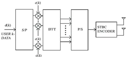
Here the system model that we have considered com-prises two asynchronous co-channel users in a MIMO MC DS/CDMA system in which each transmitting ter-minal is a MC DS/CDMA transmitter with MIMO sup-port realized through Space Time Block Codes (spatial diversity). The two co-channel users communicate with two receive antennas at the receiver, which performs interference cancellation and then detects the transmitted signal of each user. Figure 1 shows the MIMO MC DS/ CDMA transmitter .The user data at each transmitting terminal after appropriate constellation mapping is multiplied with a spreading code and the spread sym-bols of each data are multi-carrier modulated. Then the sum of all the carriers of the kth user composes the output of the kth user signal Sk(t). The total output S (t)
is the sum of all the user signals. After HPA (high power amplification), the final signal is transmitted. The transmitted signal corresponding to the nth data symbol of the kth user is
t f j c m k q m M m Q q k m k
n t d C p t qT nT e m
S 2
, 1 0 1 0 ) ( ) (
(1)where, k is the user number, m is the carrier number, q is the chip number, Tcis chip duration and T is symbol
du-ration and equals to Q Tc. Q is the length of user specific
spreading code. dmkis the data of mth sub-carrier and kth
user, cm,q k is the qth spreading code of mth carrier of kth user, pm(t) is Root raised cosine pulse of mthcarrier
and fmis the mth carrier frequency. When the total
num-ber of users is K, the total transmitted signal correspond-ing to the nth data symbol is
1 0 2 , 1 0 1 0 ) ( K k ft m j k q m M m Q q k mn t d C e
S (2)
This modulated stream is then passed through a STBC encoder which groups the symbols according to a spe-cific STBC pattern (G2) and then transmits the symbols through multiple transmit antennas. The received vector at the first receive antenna for the transmitted symbols d1
and d2is expressed as
21 11 21 11 * 1 * 2 2 1 2 1 n n h h d d d d r r (3)
where, h11 and h21 denotes the channel fading and n11
[image:2.595.318.537.78.177.2]and n21 represents the additive white Gaussian noise
Figure 1. MIMO MC DS/CDMA transmitter.
(AWGN). Let u1, u2 and v1, v2 represent the symbols
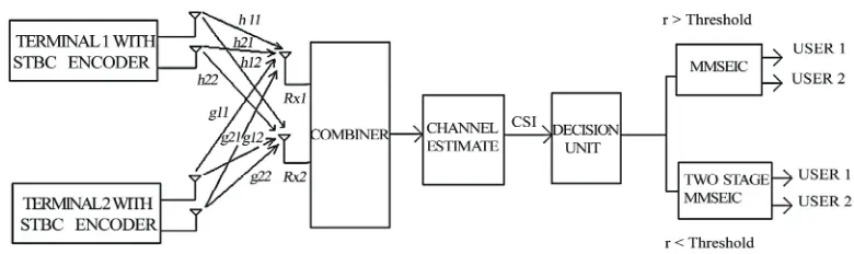
transmitted over two consecutive symbol durations by the corresponding two co-channel asynchronous users. As shown in Figure 2, let h11, h21, g11 and g21 represent
the channel fading between all the transmit antennas and the first receive antenna at the base station respectively and h12, h22, g12 and g22 represent the channel fading
be-tween all the transmit antennas and the second receive antenna at the base station respectively. Now, the re-ceived vector at the receive antenna Rx1 over the two symbol time period is expressed as
11 2 21 1 11 2 21 1 11
11
h
u
h
u
g
v
g
v
n
r
(4)12 * 1 21 * 2 11 * 1 21 * 2 11
12
h
u
h
u
g
v
g
v
n
r
(5) The received vector at the receiver antenna Rx2 is given by 21 2 22 1 12 2 22 1 1221
h
u
h
u
g
v
g
v
n
r
(6)22 * 1 22 * 2 12 * 1 22 * 2 12
22
h
u
h
u
g
v
g
v
n
r
(7)3. Improved MMSE IC ML Decoding
The overall received signal from each of the receive an-tenna is expressed as
T T
TR R
r 1 2 (8) The channel fading coefficient between each transmit-ter and the receive antenna is rearranged for each co- channel user to form a generic channel matrix. For de-tecting the first co-channel user data, the corresponding channel matrix is represented as
2 2 1 1 G H G H
H (9)
and for the second user, it is given by
2 2 1 1 ~ H G H G
H (10)
Figure 2. MIMO MC DS/CDMA with two co-channel asynchronous users and adaptive base station receiver system model.
fers for each co-channel user. For each of the two users considered here in this work, the MMSE weight matrix is computed from the expression [4,5]
2 2
1 1H ˆ1 2H 2
s w r v w r v
ˆ
0
(16)
4. Two Stage Interference Cancellation
42I
HH
M H and M~ H~H~H 2I4 (11)
The two stage interference cancellation proceeds with first decoding the data from the two terminals. Then, assuming each decoded value is correct, the data corre-sponding to the other user is estimated using Maximum likelihood estimation. i.e. first assuming the first terminal decoded data is correct based on single stage MMSE IC, the second user data is estimated from the decoded data. This is carried out by first calculating x1 and x2.
where, M is the weight matrix for the first user and M~
is the weight matrix for the second user. HH represent
the Hermitian transpose of the channel matrix and σ2 is
the noise variance. To suppress the interferences from other co-channel users, the inverse of the weight matrix is multiplied with the columns of the channel matrix that represents the channel fading for a particular co- channel user i.e.
1 1 1
.
ˆ
x
R
H c
and 2 2 2.
ˆ
1 1 1 M h
w and w~1M~1h1 (12)
x
R
H c
0 (17)where, is the data decoded, corresponding to the first user. The second user data is estimated from the first user decoded data by using the maximum likelihood es-timation given by
0
ˆ
c
where,
h1=first column of H or H~
h2=second column of H or H~
The MMSE Interference cancellation receiver sup-presses both co-channel interferences and noise compo-nents, which means that the mean square error or vari-ance between the transmitted symbols and the estimate is reduced. The maximum likelihood (ML) detection is used to detect the transmitted symbols for the corre-sponding user. The ML decoding estimates the symbols by determining the minimum Euclidian distance of all possible transmitted symbols from the received constel-lation [4], given by
0
2
0 1 1 2
ˆ
ˆ arg min{ }
s S
2 2
s x G s x G s
(18)
where, S takes all possible values in the signal constella-tion. The reliability corresponding to the estimated data is given by the expression
2
0 1 1 0ˆ 2 2 0
s
2
ˆ
x G s x G s
(19) Similarly, the first user data based on single stage MMSE IC is estimated by computing y1 and y2.
} ˆ ˆ
{ min arg
ˆ 2
2 2 2 1 1 ˆ
u r w u r w
U H H
U u
(13)
1 1 1.ˆ
y R G s1 and y2 R2G s2.ˆ1 (20) and where, sˆ1 is the data decoded corresponding to the
second user. The first user data is estimated from the second user decoded data by using the expression [4]
} ˆ ~ ˆ ~ { min arg
ˆ 2
2 2 2 1 1
ˆ w r v w r v
V H H
V v
(14)
where, and V represent the two co-channel users estimated data. , , and takes all possible values of the users signal constellation. The reliability of the decoded signals are computed by
Uˆ ˆ
1
ˆ
u uˆ2 vˆ1 vˆ2 1
2
1 1 1 2
ˆ
ˆ arg min{ }
c C
c y H c y H
2c2 (21)
The corresponding value of reliability for the esti-mated data is
2 2
0 1H ˆ1 2H 2
c w r u w r u
c1 y1H c1 1ˆ 2 y2H c2 1 2
ˆ (22)
0
The receiver computes the overall reliability for the two users i.e. 0 c0s and 1c1s1 .The decision is made on the sets of symbols computed by comparing the two reliabilities. The comparison is made as [4]
if (01)
0 0
ˆ ˆ ˆ ˆ ( , ) ( , )c s c s
else
1 1
ˆ ˆ ˆ ˆ
( , ) ( , )c s c s (23) The system illustrated in Figure 2, consists of a re-ceiver with a switch between a single and double stage MMSE IC unit, CSI (Channel State Information) and a decision unit. When the channel is slowly varying, the receiver detects the symbols based on single stage tech-nique. When the channel variation is rapid, two stage MMSE IC is employed to detect the symbols. At present, perfect channel knowledge is assumed at the receiver. The entire detection takes place based on the instantane-ous SNR available at the receiver.
5. Performance Analysis
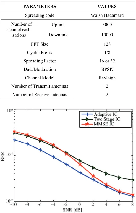
In this section, we present the performance of adaptive co-channel suppression technique for a multi-user MIMO MC DS/CDMA system. The simulation results for the single stage and two stage interference cancellation tech-niques are shown in Figures 3 and 4. The channel model considered is quasi-static Rayleigh fading channel, which is built on the classical understanding of Doppler shift and delay spread. The modulation scheme employed is BPSK, as it provides the best system throughput for MIMO realization based on STBC. The number of channel realizations considered for uplink and downlink is 5000 and 10000 respectively for each value for SNR. Table 1 summarizes the simulation parameters.
[image:4.595.308.538.93.453.2]Simulation results divulge that, at low SNR value, two stage interference cancellation techniques perform well whereas at high SNR value single stage MMSE IC with ML decoding provides better BER performance. Hence, a trade off can be made in selecting the inter-ference cancellation techniques at the receiver when the SNR dwindles. This can result in better performance of MIMO MC DS/CDMA system in an interference lim-ited environment as switching of IC can be made in an adaptive manner.
Figure 3 shows the uplink performance of MIMO MC DS/CDMA system with single stage IC, two stage IC and adaptive IC for two co-channel users. Each user data is spread by a spreading factor of 32. Here in each MC DS CDMA system one user is accommodated. It can be discerned that adaptive IC outperforms both single stage and double stage. The same performance can also be realized over the downlink channel. Figure 4 elucidates
Table 1. Simulation parameters.
PARAMETERS VALUES
Spreading code Walsh Hadamard
Uplink 5000 Number of
channel
reali-zations Downlink 10000
FFT Size 128
Cyclic Prefix 1/8
Spreading Factor 16 or 32
Data Modulation BPSK
Channel Model Rayleigh
Number of Transmit antennas 2
[image:4.595.308.537.94.455.2]Number of Receive antennas 2
Figure 3. Performance of adaptive co-channel interference scheme for 2 co-channel users over an uplink communica-tion channel for MIMO MC DS/CDMA system.
[image:4.595.310.536.500.678.2]the performance of the same system with four co-channel users, with each user spread by a spreading factor of 16 over downlink communication channel. Here also adap-tive switching scheme provides better BER performance.
6. Conclusions
In this work, we considered a two stage MMSE co-channel interference cancellation receiver for MIMO MC DS/ CDMA systems. MC DS /CDMA can be realized as a prominent air interface for 4G Broadband communica-tions; however, capacity of such systems is limited by interference. Mitigating the various interferences can result in confronting the future generation wireless networks needs. In this paper we have analyzed a two stage IC technique for a multi-user environment. Results of our analysis reveal that a trade off could be made in selecting the IC techniques for mitigating CCI. It could be dis-cerned that at low SNR values two stage has resulted in better performance because of its iterative nature while at high SNR values, single stage performs better. Also, it is expounded from our analysis that the adaptive in-terference cancellation receiver has resulted in better suppression of CCI.
7. References
[1] L. Hanzo, L-L. Yang, E-L. Kuna, and K. Yen, “Single and multi-carrier DS-CDMA multi-user detection, space-time spreading, synchronization and standards,” IEEE Press, 2003. [2] M. K. Simon and M. S. Alouini, “BER performance of
multi-carrier DS-CDMA systems over generalized fading channels,” IEEE International Conference, 1999. [3] E. Bigieri, R. Calderbank, A. Constantinides, A.
Gold-smith, A. Paulraj, and H. Vincent Poor, “MIMO wireless communications,” Cambridge University Press, 2007. [4] Anand. V, Arvind. S, and Lakshmi Krishnan,
“Investiga-tions on the performance of MIMO assisted Multi Carrier DS/CDMA system with multi-user detection for 4G mobile communications,” Dissertation, SSN Institutions, 2009. [5] Prabagarane Nagaradjane, Arvind Sai Sarathi Vasan, and
Lakshmi Krishnan, “A robust space time co-channel inter-ference mitigation and detection technique for multi-user MIMO multi-carrier DS/ CDMA systems,” Proceedings of IEEE International Conference, Wireless Vitae, 2009. [6] S. Kondo and L. B. Milstein, “Performance of