A Modified T/2 Fractionally Spaced Coordinate
Transformation Blind Equalization Algorithm
Yecai GUO1,2, Xueqing ZHAO1, Zhenxin LIU1, Min GAO1
1School of Electrical Engineering and Information, Anhui University of Science and Technology, Huainan, China 2College of Electronic and Information Engineering, Nanjing University of Information Science and Technology,
Nan-jing, China Email: guo-yecai@126.com
Received November 3, 2009; revised December 13, 2009; accepted January 19,2010
Abstract
When T/2 Fractionally Spaced blind Equalization Algorithm based Constant Modulus Algorithm (T/2-FSE- CMA) is employed for equalizing higher order Quadrature Amplitude Modulation signals (QAM), it has dis-advantages of low convergence speed and large Mean Square Error (MSE). For overcoming these disadvan-tages, a Modified T/2 Fractionally Spaced blind Equalization algorithm based on Coordinate Transformation and CMA (T/2-FSE-MCTCMA) was proposed by analyzing the character of 16QAM signal constellations. In the proposed algorithm, real and imaginary parts of input signal of T/2 fractionally spaced blind equalizer are equalized, respectively, and output signals of equalizer are transformed to the same unit circle by coordi-nate transformation method, a new error function is defined after making coordicoordi-nate transformation and used to adjust weight vector of T/2 fractionally spaced blind equalizer. The proposed algorithm can overcome large misjudgments of T/2 fractionally spaced blind equalization algorithm for equalizing multi-modulus higher order QAM. Simulation results with underwater acoustic channel models demonstrate that the pro-posed T/2-FSE-MCTCMA algorithm outperforms T/2 Fractionally Spaced blind Equalization algorithm bas- ed on Coordinate Transformation and CMA (T/2-FSE-CTCMA) and the T/2-FSE-CMA in convergence rate and MSE.
Keywords:Blind Equalization; Underwater Acoustic Channel; Coordinate-Transformation; Fractionally Spaced Equalizer.
1. Introduction
In underwater acoustic communication system, blind eq- ualization technique without training sequence is an im-portant means to eliminate intersymbol interference (ISI) [1–5]. Among them, baud-spaced equalizer based on Constant Modulus Algorithm (BSE-CMA) has simple structure, but its convergence rate is slow and its steady error is large [6,7]. Whereas, fractionally-spaced equal-izer based on constant modulus algorithm (FSE-CMA) is employed for equalizing constant modulus signal, its convergence rate is fast and its steady error is low [8–10]. When the FSE-CMA is used to equalize high-order QAM signal, it can produce large misjudgments and lead to large mean square error, because higher order QAM signal constellations distribute in the several known cir-cles and its module value is not constant [11,12].
There-fore, intersymbol interference is not sufficiently elimi-nated.
In the paper, on the basis of analyzing the character of 16QAM signal constellations [13–15], T/2 fraction-ally-spaced equalizer, and the thought of coordinate transformation [16] real and imaginary parts of output signal of each sub-channel are equalized, respectively, a new constant modulus error function is defined after ma- king coordinate transformation to output of each equal-izer. A cost function based on this error function is given. Iterative formula of weight vector of T/2 fractionally-sp- aced equalizer is got by making the cost function mini-mization. Finally, a Modified T/2 Fractionally Spaced blind Equalization algorithm based on Coordinate Transformation and CMA (T/2-FSE- MCTCMA) is es-tablished.
frac-)
i k
n
)
tionally spaced blind equalization algorithm is described. In Section 3, the T/2-FSE-MCTCMA is proposed. The performance of the proposed T/2-FSE-MCTCMA is analyzed in Sections 4 and 5. Finally, some conclusions are obtained.
2. Fractionally Spaced Blind Equalization
Algorithm
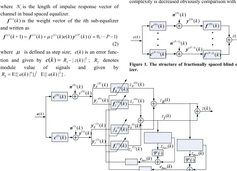
Relevant researches show that fractionally spaced equal-izer is equivalent to multi-channel system model [17–19]. Its structure is shown in Figure 1 Input and out-put signals of this system have the same sampling rate.
In Figure 1, is the transmitted signal sequence and its sampling period is ;
is an impulse response vector of the ith sub-channel and ; is fractionally spaced sampling factor; is an additive noise vector of the
ith sub-channel; is an input signal vector of the
ith blind equalizer and written as
( ) a k
1)P
( )i (
n
( )i (
y
T
P
( )i ( )k
c (i0,1P1
( )i ( )k
c c k[( i1]
) k ) k 1 ( ) ( ) ( ) 0
( ) c ( ) ( ) ( )
N
i i
j
k a j c j
y (1)
where is the length of impulse response vector of channel in baud spaced equalizer.
c
N
( )i ( )k
f is the weight vector of the ith sub-equalizer and written as
( )i (k +1) ( )i ( )k z( )i ( ) ( )k e k ( )i *( ) (k i0,P 1
f f y
(2) where
is defined as step size; is an errorfunc-tion and given by 2 ; 2 denotes
module value of signals and given by ( )
e k
2
| ( )
R z k
( )
e k
| R4
2 E{| (
R a
The output signal of the whole system is given by
1
( )* ( 1)
0 1
( )* ( 1) ( 1)
0
( ) ( ) ( )
( )[ ( ) ( ) ( )]
P
i P i i
P
i P i P i i
z k k k
k k k k
* f yf a c n
(3)
where “*” denotes conjugate operator.
Fractionally Spaced blind Equalization algorithm bas- ed CMA(T/2-FSE-CMA)is only suitable to equalize co- nstant modulus signals. When it is employed for equal- izing multi-modulus QAM signal, it can easily produce large mean square error.
3. Modified T/2 Fractionally Spaced
Coordinate Transformation Blind
Equalization Algorithms
When the transmitted signal is higher order QAM signal, we make Figure 1 change in two aspects in order to ob-tain good equalization performance. At first, the real and imaginary parts of input signal are equalized, respectively. It is equivalent to process real signals in the whole equalization process. Moreover, its computational
( ) a k
complexity is decreased obviously comparison with that
( )
a k z k( )
(0)( )k
c
(0)( )k
n
(0)( )k
y (0)
( )k f
(P1)( )k
c
(P1)( )k
n
y(P1)( )k f(P1)( )k [image:2.595.56.518.368.702.2]
Figure 1. The structure of fractionally spaced blind equal-izer.
) | }
k
E{| ( ) | }a k 2 .
( )k
a
(0)( )k
c
(0) ( )k n
(0)( )
y k
(0)( )
R k
y
(0)( )
I k y (0) ( ) R z k
(0)( )
I
z k
(1)( )
I k
y
(1)( )
R
z k
z kR( )(1)( )
R k
y
(1)( )
I
z k
( )
Rnew
e k
(0)( )
R k
f
(0)( )
I k
f
(1)( )
I k
f
(1)( )k
c
(1)( )k
n
(1)( )k
y
( ) I z k
(1)( )
R
f k
( )
Inew
e k
( ) ( ) Rnew z k ( ) Inew z k ( ) ( ) z k
k k
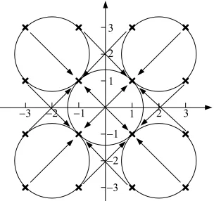
of the complex signals. The second, two error functions are defined after making coordinate transformation to the real and imaginary parts of output signal z k( ) and the cost functions based on these two error functions are obtained. Accordingly, the updating formula of weight vector of modified equalizer is given by making the cost function minimization. The structure diagram of the modified equalizer is shown in Figure 2. We call the modified equalizer as T/2-FSE-MCTCMA(Modified T/2 Fractionally Spaced blind Equalization algorithm based on Coordinate Transformation and CMA. In the pro-posed T/2-FSE-MCTCMA, according to Figure 2, the channel is divided into odd sub-channel and even
sub-channel , and and are input
signals of each equalizer in the T/2-FSE-MCTCMA and written as
(0)( )k
c
(1)( )k
y
(1)( )k
c y(0)( )k
(0)( ) (0)( ) (0)( )
R I
k k j
y y y (4)
(1)( ) (1)( ) (1)( )
R I
k k j
y y y (5)
For sub-channel , its has real and imaginary equalizer. The weight vectors of the real and imaginary
equalizer are expressed as and ,
re-spectively, and , are output signals of
the real and imaginary equalizer. As for sub-channel , the weight vectors of real and imaginary
equal-izer are expressed as and , the output
signals of the real and imaginary equalizer are expressed and I , respectively. The real part of the
final output is written as
(0)( )k
c
(0)( )
z k
(1)
R
f
( )k
(0)( )
R k
f
(0)( )
z k
( )k fI
(0)( )
I k f ) R (1) z I
(1)( )k
c
(1)( )
R z (1)(k k (0) (1) ( ) ( ) ( )
R R R
z k z k z k (6) The imaginary part of the final output is written as
(0) (1)
( ) ( ) ( )
I I I
z k z k z k (7) The final output signal of the equalizer is written as
[image:3.595.97.249.544.687.2]2 3 2 3 2 3 2 3 1 1 1 1
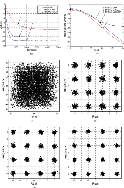
Figure 3. The coordinate transformation of 16 QAM sig-nals.
( ) R( ) I( )
z k z k jz k (8) In the process of equalization, coordinate transformation method is introduced into blind equalization algorithm, the principle diagram of the coordinate transformation is shown in Figure 3.
In Figure 3, “
” denotes ideal 16 QAM signal points after equalization, these points distribute in four known circles. We can make ideal 16 QAM signal points be-come four points A, B, C, and D via making coordinate transformation to output signals of the real and imagi-nary equalizer. A, B, C, and D must distribute in a circle.When the CMA is used to equalize 16QAM signal, the
error function is written as ( is a
specific module value). Even if the channels are equal-ized completely, the error is not zero. This affects equalization results. So, coordinate transformation method is used to make 16QAM signal points in differ-ent circles turn into A, B, C, D four points in the same circle. In other words, after multi-modulus 16QAM sig-nals is become constant modulus 4QAM sigsig-nals, the er-ror is zero under the condition that the channels are equalized completely. The performance of the algorithm based on coordinate transformation method (T/2-FSE-
2 2
( ) | ( ) | e k R z k
( ) e k
2 R
MCTCMA) is optimal.
In Figure 2, and are the error
func-tion of the real and imaginary part after coordinate transformation, respectively, and defined as
( )
Rnew
e k eInew( )k
2
( ) | |
Rnew Rnew Rnew
e k R z 2 2
(9) 2
( ) | |
Inew Inew Inew
e k R z (10) where
( ) ( ) 2sgn[ ( )]
Rnew R R
z k z k z k (11)
( ) ( ) 2sgn[ ( )]
Inew I I
z k z k z k (12)
2 {| [ ( ) 2sgn[ ( )]] {| [ ( ) 2sgn[ ( )]]
R R
Rnew
R R
E a k a k
R
E a k a k
(13)
2 {| [ ( ) 2sgn[ ( )]] {| [ ( ) 2sgn[ ( )]]
I I
Inew
I I
E a k a k
R
E a k a k
(14)
The updating formula of weight vector of the real and imaginary equalizer are written as
( )i ( 1) ( )i ( ) ( )i ( ) ( ) ( )i *( ) ( 0,1 R k + R k zR k eRnew k R k i
f f y )
(15)
( )i (k +1) ( )i ( )k z ( )i ( )k e ( )k ( )i *( ) (k i 0,1)
I I I Inew I
f f y
(16) The final output signal of equalizer is written as
1 1 ( ) ( ) ( ) ( ) 0 0 ( ) ( ) ( ) ( ) ( ) ( ) ( ) R I P P
i i i i
R R I P
i i
z k z k jz k
f k y k j f k y k
0 1000 2000 3000 4000 5000 -18
-16 -14 -12 -10 -8 -6 -4 -2 0
Iterations
M
SE/
dB
1
3 2
1 T/2-FSE-CMA 2 T/2-FSE-CTCMA 3 T/2-FSE-MCTCMA
5 10 15 20 25 30
-27 -26 -25 -24 -23 -22 -21 -20 -19 -18
SNR
M
ea
n S
qua
re
E
rr
or
/dB
1
3 2
1 T/2-FSE-CMA 2 T/2-FSE-CTCMA 3 T/2-FSE-MCTCMA
(a) (b)
-5 0 5
-5 -4 -3 -2 -1 0 1 2 3 4 5
Ima
g
inar
y
Real
-3 -2 -1 0 1 2 3
-3 -2 -1 0 1 2 3
Im
a
g
in
a
ry
Real
(c) (d)
-3 -2 -1 0 1 2 3
-3 -2 -1 0 1 2 3
Ima
g
inar
y
Real
-3 -2 -1 0 1 2 3
-3 -2 -1 0 1 2 3
Im
a
g
in
a
ry
Real
[image:4.595.92.504.66.689.2](e) (f)
1
To 16 QAM signals, when the channel is equalized completely, Formula (9) is equal to zero. Until this, the T/2-FSE-MCTCMA is established. In this paper, we call the algorithm that the real and imaginary parts of input signal are not equalized, respectively, and only output signal is transformed as T/2 Fractionally Spaced blind Equalization algorithm based on Coordinate Transforma-tion and CMA (T/2-FSE-CTCMA).
4. Performance Analysis
4.1. Convergence Performance Analysis
[image:5.595.308.534.626.710.2]Input signal is sampled by the rate of in T/2 frac-tionally spaced equalizer. It avoids spectrum aliasing by sub-sampling and compensates distortion of channel [19,20]. The real and imaginary parts of input signals in T/2 fractionally spaced equalizer are equalized, respec-tively, so it is equivalent to process real signal in the whole equalization process, and its computational com-plexity is decreased obviously. After the coordinate tran- sformations of the real and imaginary parts of output signal are carried out, the mutli-modulus 16QAM signal is become constant modulus 4QAM signal. This treat-ment accelerates the updating speed of weight vector and when the channel is perfectly equalized, the error func-tion tends to zero. So, the residual mean square error is decreased and the convergence rate is improved at end equalization.
/ 2
T
4.2. Analysis of Computational Complexity
In the T/2-FSE-CMA, each weight vector iteration needs multiplications and
additions ( is the length of equalizer). However, in the T/2-FSE-MCTCMA, the computation load of real part of each weight vector iteration is multiplications
and additions. So, the total computation
load of each weight vector iteration is 4(Nf / 2)
(Nf /
3(Nf / 2) [( Nf / 2) 1]
/ 2
f
N
f
N
2)
f
N
multiplica-tions and additions. Based on above analysis, the computation load of the T/2-FSE-MCTCMA has a drop of about a half comparison with that of the T/2-FSE-CMA.
2
f
N
5. Simulation Results
In order to test the validity of the T/2-FSE-MCTCMA, we carried out simulation tests and compared the T/2-FSE-MCTCMA with the T/2-FSE-CTCMA and the T/2-FSE-CMA.
Simulation Test 1: 16QAM signals were transmitted to mixed-phase water acoustic channel, the impulse respon-
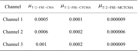
se vector of this channel was given by c=[0.3132 -0.1040 0.8908 0.3134] [21]; The SNR was set to 25 dB; the weight length of equalizer was set to 32; the weight length of each sub-channel equalizer was set to 16; the center tap of the weight vectors of all equalizer were initialized to one; the step sizes T/ 2 FSE ,
T / 2 FSE CTCMA
,
T/2 FSE MCTCMA were set to 0.000006, 0.00003, 0.0009, respectively. Simulation re-sults of 5000 Monte-Carlo times were shown in Figure 4.Figure 4(a) shows that the MSE of the T/2-FSE- MCTCMA has a drop of about 2dB or 5dB comparison with that of the T/2-FSE-CTCMA or the T/2-FSE-CMA, respectively; the convergence rate of the T/2-FSE- MCTCMA is the fastest in all algorithms and performs an improvement of about 2000 steps comparison with the T/2-FSE-CMA. Root mean square error of the T/2-FSE- MCTCMA is minimum under the condition of the dif-ferent SNR (see Figure 4(b)). The constellations of out-put signals in the T/2-FSE-MCTCMA is the clearest (see Figure 4(d), (e) and (f)). So, the T/2-FSE MCTCMA has great ability to suppress intersymbol interference.
Simulation Test 2: transfer function of the channel
was given by [21].
After 5000 signal points were transmitted, the channel was changed into the channel , its transfer
func-tion was given by [21]. After 10000
signal points were transmitted, the channel was changed into the channel , its transfer function was
given by [21]. This
established channel was called as time-varying channel.
1 c =[0.9656 -0.0906
1
c
2=[-0.35 0 0 1 c
3 c 0.3132 -0.1040 0.890
0.0578 0.2368]
2 c
]
2 c
8 0.3134] 1
c
3=[
c
The transmitted signals were 16QAM signal; the SNR was set to 25 dB; the weight length of equalizer was set to 32; the weight length of each sub-channel equalizer was set to 16; the center tap of the weight vectors of all equalizer were initialized to one. In the time-varying channel, the step sizes of the three algorithms were shown in Table 1. Simulation results of 500 times Monte-Carlo were shown in Figure 5.
Figure 5(a) illustrates that the T/2-FSE-MCTCMA outperforms the T/2-FSE-CTCMA and T/2-FSE-CMA in equalizing the time-varying channel and has strong re-started ability and can rapidly track time-varying channel
Table 1. The step size of three algorithms.
el
Chann T / 2 FSE CMA T/ 2 FSE CTCMA T/2 FSE MCTCMA
Channel 1 0.0005 0.0001 0.000009
Channel 2 0.0006 0.0002 0.000006
0 5000 10000 15000 -16
-14 -12 -10 -8 -6 -4 -2 0 2 4
Signal Points
MS
E
/d
B
1 2
3 1 T/2-CMA 2 T/2-CTCMA 3 T/2-MCTCMA
1 2
3
1
2 3
-3 -2 -1 0 1 2 3 -3
-2 -1 0 1 2 3
Im
agi
n
ar
y
Real (a) (b)
-3 -2 -1 0 1 2 3
-3 -2 -1 0 1 2 3
Im
a
g
in
a
ry
Real
-3 -2 -1 0 1 2 3
-3 -2 -1 0 1 2 3
Im
agi
n
ar
y
Real
[image:6.595.93.512.74.475.2](c) (d)
Figure 5. Simulation Results. (a) Error curve; (b) Output signals of T/2-FSE-CMA; (c) Output signals of T/2-FSE-CTCMA; (d) Output signals of T/2-FSE-MCTCMA.
and that the output constellations of the T/2-FSE- MCTCMA are also the clearest.
6. Conclusions
In this paper, a Modified T/2 Fractionally Spaced blind Equalization algorithm based on Coordinate Transforma-tion and CMA(T/2-FSE-MCTCMA) is proposed, its computation load has a drop of about a half comparison with that of the T/2-FSE-CMA(T/2 Fractionally Spaced blind Equalization algorithm based on CMA). For 16QAM signals, the equalization performance of the T/2-FSE-MCTCMA is optimal. Simulation results with the different underwater acoustic channels indicate that the T/2-FSE-MCTCMA has faster convergence speed, the lower MSE, and the clearest constellations compari-son with the T/2-FSE-CTCMA(T/2 Fractionally Spaced blind Equalization algorithm based on Coordinate Tr-
ansformation and CMA) and the T/2-FSE-CMA. So, the T/2-FSE-MCTCMA can effectively eliminate Intersym-bol Interference(ISI) and recovery signals real-timely.
7. Acknowledgment
This paper is supported by Specialized Fund for the Au-thor of National Excellent Doctoral Dissertation of China (200753), Natural Science Foundation of Higher Educa-tion InstituEduca-tion of Jiangsu Province (08KJB510010) and “the peak of six major talent” cultivate projects of Ji-angsu Province(2008026), Natural Science Foundation of Jiangsu Province(BK2009410).
8. References
sources: Energy matching approach,” Electronics Letters, Vol. 42, No. 4, pp. 247–248, 2006.
[2] Z. J. Liu, H. S. Xu, J. L. Wang, and K. C. Yi, “A novel hybrid blind equalization algorithm,” Journal of Elec-tronic and Information Technology, Vol. 81, No. 7, pp. 1606–1609, 2009.
[3] O. Dabeer and E. Masry, “Convergence analysis of the constant modulus algorithm,” IEEE Transactions on In-formation Theory, Vol. 49, No.6, pp. 1447–1464, 2003. [4] G. C. Li, C. B. Luo, X. G. Yang and Y. H. Gong, “New
convex combination strategy for the MMSE blind equalization algorithms,” Journal of Electronic Meas-urement and Instrument, Vol. 23, No. 1, pp. 37–41, 2009. [5] Y. Wang and W. Guo, “Blind equalization of constant
modulus based on Support Vector Regression,” Journal of Electronic Measurement and Instrument, Vol. 22, No. 3, pp. 15–19, 2008.
[6] J. Liu and L. Y. Dai, “New Blind Equalization Algorithm Based on Multi-mode Error Switch,” Journal of Data Acquisition and Processing, Vol. 19, No. 2, pp. 167–170, 2004.
[7] X. L. Li and X. D. Zhang, “A family of generalized con-stant modulus algorithms for blind equalization,” IEEE Trans on communications, Vol. 54, No. 11, pp. 1913– 1917, 2006.
[8] Y. P. Zhang and J. W. Zhao. “Blind equalization algo-rithms based on fractionally spaced underwater acoustic channels,” Acoustics and Electronics Engineering, Vol. 78, No. 2, pp. 21–23, 2005.
[9] L. Zhou, J. D. Li and G. H. Zhang. “Novel DWPW sys-tem based on fractionally spaced equalizers and the maximum likelihood algorithm,” Journal of Xidian Uni-versity (Natural Science), Vol. 33, No. 4, pp. 509–513, 2006.
[10] Y. C. Guo and R. G. Lin, “Blind equalization algorithm based on T/4 fractionally spaced decision feedback equalizer,” Journal of Data Acquisition and Processing, Vol. 23, No. 3, pp. 284–287, 2008.
[11] K. S. Chen and C. Y. Chu, “A propagation study of the
28GHz LMDs system performance with M-QAM modu-lations under rain fading,” Progress In Electromagnetics Research, No. PIER 68, pp. 35–51, 2007.
[12] Y. P. Zhang, Y. C. Guo and J. Z. Liu, “Blind equalization algorithm suitable for 16QAM signals for carrier recov-ery of underwater acoustic channel,” Journal of System Simulation, Vol. 20, No.1, pp. 156–158, 2008.
[13] Y. Q. Zhang, P. Li and Z. R. Zhang, “Dual-mode blind equalization algorithm for multi-lever QAM modulation based on Sign-CMA,” Journal of China Institute of Communication, Vol. 25, No. 5, pp. 155–159, 2004. [14] G. Q. Dou, J. Gao and P Wang, “A concurrent constant
modulus algorithm and soft decision-directed algorithm for blind equalization,” Signal Processing, Vol. 23, No. 6, pp. 833–835, 2007.
[15] W Rao and Y. C. Guo, “A new constant modulus algo-rithm based on dual-step size,” International Symposium on Test Automation and Instrument, 2006.
[16] W. Rao, K. M. Yuan, Y. C. Guo and C. Yang, “A simple constant modulus algorithm for blind equalizer suitable for 16QAM signal,” International Conference on Signal Processing Proceedings, pp. 1963–1966, 2008.
[17] Y. C. Wang, Z. L. Chen and Z. T. Liu, “Direct blind frac-tional spaced equalization algorithm based on channel output decorrelation,” Journal of Data Acquisition and Processing, Vol. 20, No. 3, pp. 323–327, 2005.
[18] L. Zhou, J. d. Li and G. H. Zhang, “Novel DWPW sys-tem based on fractional spaced equalizers and the maxi-mum likelihood algorithm”. Journal of XiDian University, Vol. 33, No. 4, pp. 509–513, 2006.
[19] Y. C. Guo, “Adaptive blind equalization techniques,” Hefei Industrial University Press, 2007.
[20] B. J. Kim and D. C. Cox, “Blind equalization for short burst wireless communications,” IEEE Trans. On Ve-hicular Technology, Vol. 49, No. 4, pp. 1235–1247, 2000.