© 2019, IRJET | Impact Factor value: 7.34 | ISO 9001:2008 Certified Journal | Page 177
Implementation and Analysis of Hybridization in Modified Parallel
Adder Circuits
Diptangshu Chattopadhyay
1, Avinaba Tapadar
2, Sujan Sarkar
31 UG Student, Dept. of ECE, Jalpaiguri Government Engineering College, West Bengal, India
2 UG Student, Dept. of ECE, Jalpaiguri Government Engineering College, West Bengal, India
3 B.Tech, ECE, Jalpaiguri Government Engineering College, West Bengal, India
---***---Abstract
—In today’s electronic world, we need a perfectbalance between device speed, power and area efficient path. Most of the computational components contain adder circuits in them which greatly affects the operation time. The number of transistors in the VLSI circuit can only be reduced up to a certain limit. So, to increase the efficiency there is a need for modification and hybridization of different adders. SQRT is a significant model. Adders like CSA-CSkA hybrid adder, CSA-CIA hybrid adder and modified CSLA using D-LATCH have been compared here on the basis of delay, power consumption and area calculations. Verilog hardware description language (HDL) was used for coding and the simulation was done with the support of Xilinx ISE 14.7 environment. The paper focuses on the comparative study between adders. At the end, we are successful in figuring out the adder taking the least amount of delay, area and power consumption.
Keywords—Modified Adder, Ripple Carry Adder (RCA),
Carry Save Adder (CSA), Carry Skip Adder (CSkA), Carry Increment Adder (CIA), Propagation Delay, Area efficient, Power consumption, Hybrid Adder.
1. INTRODUCTION
From last few years we are witnessing a switch from 32 bit to 64 bit microprocessors and even more. With a thriving demand for speed centric technologies, Very Large Scale Integration (VLSI) has become the most sought after field of research for designing area and power efficient system with high speed data path logic. But maintaining a balance between the parameters is highly important. To make the VLSI circuit more portable with low computational delay, we try to modify the fundamentally important adder circuits present in them. Calculations like division, multiplication, addition, subtraction, and logical operations such as INV, OR, AND can be encompassed by the basic adder circuits included in the Arithmetic Logic Unit (ALU).
Half adder was the first proposed adder with two operands, output sum and carry [1]. Following the success of half
adder, a full adder circuit was proposed with 3 operands. At the output side we have the sum and carry, very much similar to that of half adder. We can have Cin as the third input. A single circuit’s operation is limited to a single bit addition. To remove this drawback and perform multi-bit operation we have to connect a number of Full Adders in parallel combination which is nothing but a Ripple Carry Adder (RCA) model. In the case of high speed computation there is an issue of time lag in propagating the carry generated in (n-1)th block to (n)th block of the adder.
Modified adders like Carry Look Ahead Adder (CLA), Carry Save Adder (CSA) [6] [8], Carry Skip Adder (CSkA) [8] [9], Carry Select Adder (CSLA), and Carry Increment Adder (CIA) have been designed so far [9] [10]. There are also a number of hybrid adders like CIA-CLA and CIA-RCA with less delay and penalty of more power consumption.
Keeping in mind both the advantages and disadvantages of CSA and CSkA, the Proposed CSA-CSkA Hybrid Adder is designed such a way that it can operate on three inputs to speed up the calculation. Here CSkA is used instead of a simple RCA after the first stage because it is more efficient than RCA in higher bit operations. We reduce the circuit complexity by using only one skip block [2]. Similarly to reduce complexity in our proposed CSA-CIA Hybrid Adder, less number of FA blocks has been used compared to that in simple CSA circuit. In our Modified CSA we have used Square Root (SQRT) technique to make it more area efficient as well as power efficient.
2. BASIC CONCEPTS
2.1 Ripple Carry Adder (RCA)
© 2019, IRJET | Impact Factor value: 7.34 | ISO 9001:2008 Certified Journal | Page 178 combination of multiple Full Adder blocks cascaded in series.
RCA is designed in such a way that the carry generated in (n-1)th block to (n)th block of the adder. Fig. 1. shows a conventional 4-Bit Ripple Carry Adder.
Fig.-1: A 4-Bit conventional RCA
Let us perform an addition operation which will involve two 4-bit input with A = 1 1 0 0 and B = 1 0 0 1. In the first stage, addition will occur taking inputs A0 = 0 and B0 = 1 (Right extreme end). We will get S0 =1 and C1 =0. C1 will propagate to the next block. So for the second Full Adder block the inputs will be A1= 0, B1= 0 and C1= 0 which in turn will generate S1 =0 and C2 = 0. This will propagate like the previous stage. Successively we will have S2=1, C3 =0 and S3=0 and carry-out (C4) =1 as an ultimate output.
1 1 0 0 + 1 0 0 1
____________________________ 1 0 1 0 1
S3 S2 S1 S0 In this case carry-out=1
2.1.1 Advantages & disadvantages of RCA
Having less circuit complexity makes it simple to fabricate. In fact it has the simplest design amongst all multiple bit adder circuits. But unfortunately it faces disadvantages too. The main cause of its huge delay is due to the propagation of carry generated in each block, to the next block. So for N-bit addition we have to use N number of Full adder blocks. As a result, with the increase in bit size, overall delay and power consumption increases. The Total delay (Td) of a Ripple Carry Adder is given by Td= (N-1)tc + ts. Here N is the total number of gates used in a RCA, tc and ts denotes the carry propagation delay and sum propagation delay. Its delay can be functionalized by O(n) where n is number of bits. Fig. 2. Shows a Register Transfer Level (RTL) Schematic diagram of a 8-bit RCA.
Fig-2: RTL Schematic diagram of 8-bit RCA
2.2 Carry Save Adder (CSA)
Basically a Carry Save Adder is a combination of RCA. But rather than propagating the carry, CSA saves it and calculates it later. Let us imagine that we have to add three numbers A, B, and C. Carry Save Adder arranges it into the form A+ B+ C = S + C. CSA has n number of full adder which perform the separate summation and develops the carry individually. After shifting the carry on the left side we can calculate the entire sum. The schematic diagram of the Carry Save Adder is shown in Fig. 3.
Fig-3: 4-bit Carry Save Adder
2.2.1 Advantages & Disadvantages of CSA
© 2019, IRJET | Impact Factor value: 7.34 | ISO 9001:2008 Certified Journal | Page 179
[image:3.595.48.562.46.218.2]
Fig-4: RTL schematic of 8-bit CSA adder
2.3 Carry Skip Adder (CSkA)
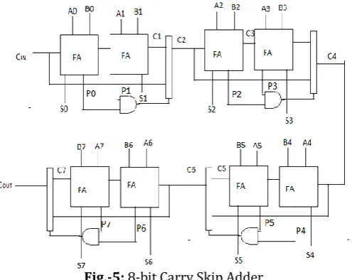
A Carry Skip Adder is also called as Carry Bypass Adder. It improves the delay of a RCA with very little modification. Carry Skip Adder (CSkA) uses skip logic in the propagation of carry. For each input bit pair operands, the propagation-conditions are determined using an XOR gate. When all propagate conditions are true(1), then carry-in bit decides the carry-out bit. A standard n bit CSkA contains n bit carry ripple chain, an n-input AND gate and a multiplexer. Carry skip adder has delay in the order of O(n). Bowing down to increasing demand for fast computational speed, most PCs nowadays work on 64 bit architecture or above. As it has a great response in higher bit, CSkAs has been accepted widely [2]. Fig. 5. Illustrates a 8 bit Carry Skip Adder.
Fig.-5: 8-bit Carry Skip Adder
2.3.1 Skip Logic Circuit
Fig. 6. Shows the the skip logic circuit of a 2-bit operation. The circuit uses a MUX [3]. It can also be replaced by an OR gate.
Fig. 6: 2-bit Carry Skip Circuit with Skip Logic
2.3.2 Advantages & Disadvantages of CSkA
CSkA is highly efficient for higher bit operations. Its skip logic makes it much faster than other available adders. The Pi logic circuit can be obtained from the Full Adder circuit itself. But for a 4-bit operation we have to use 2 carry skip logic circuits, making it consume more power. In case of lower bit operation also, it has high power, delay and area making it highly unsuitable. Fig.7. shows a RTL schematic of a 8-bit CSkA.
[image:3.595.311.554.411.546.2]
Fig-7:RTL schematic of 8-bit CSkA
2.4 Carry Increment Adder ( CIA )
[image:3.595.39.287.459.656.2]© 2019, IRJET | Impact Factor value: 7.34 | ISO 9001:2008 Certified Journal | Page 180
Fig-8: Carry Increment Adder
The operation is carried out in parallel by 2 blocks of 4-bit RCA and the carry out of the first block is transferred to the increment circuit. Increment adder is shown in Figure 9.
Fig-9: 4 Bit Increment Adder
2.4.1 Advantages & Disadvantages of CIA
Half Adder (HA) blocks are used by CIA for carry propagation. We know that carry propagation in HA is much faster than that of Full Adder (FA). That’s why total propagation delay in CIA is much less that other adders. It has less circuit complexity and is effective in higher bit operation. But as CIA needs an additional carry increment circuit, higher power consumption than RCA becomes a major drawback. Chip area is higher than that of a similar n-bit RCA circuit. In lower n-bit operation, it is not much competent.
2.5 Carry Select Adder using Binary to Excess Converter
The main drawback of conventional CSLA is its large area than other multi-bit adder circuits. To make it area efficient an (n+1)-bit Binary to excess 1 converter is used instead of n-bit RCA with Cin=1, Then the area count of group 2 is determined as follows [4]:
Gate count = 43 (FA + HA + Mux + BEC) FA = 13 (1 * 13) HA = 6 (1 * 6)
Mux = 12 (3 * 4)
NOT = 1 AND = 1
XOR = 10 (2 * 5)
BEC (3-BIT) = NOT + AND + XOR = 12
In every group each of the Ripple Carry Adder will generate partial sum and carry taking carry input as Cin = 0. An (n+1)-bit Binary to excess 1 converter is used instead of n-bit RCA with Cin=1. After that a multiplexer selects the final sum and carry. In the case of two n-bit addition the partial sums and partial carries that are generated are S0, C0out for Cin=0 and Sin, C1outfor Cin=1. Equations from (5) to (9) presents the logical operations relevant to the BEC [5]. Fig 10. shows a 16- bit CSLA using BEC.
S1(0) =S0(0) ………(5)
C1(0) = S0(0) ………..…(6)
S1(i) = S0(i) C1(i-1)……….……..………(7)
C1(i) = S0(i).C1(i-1) ………....……....(8)
C1out = C 0
(n-1) C1(n-1) ……….….(9)
Fig-10:16-bit CLSA using BEC
2.5.1 Advantages & Disadvantages of a 16-bit CSLA using BEC
The area efficiency of CSLA is more which consumes less power than the previous model. BEC based 16-bit CSLA also has less delay than RCA. But unfortunately it has less computational speed than conventional CSLA.
2.6 Modified CSLA using D-LATCH
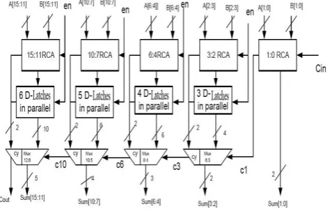
© 2019, IRJET | Impact Factor value: 7.34 | ISO 9001:2008 Certified Journal | Page 181 either with the input of Cin=1 or Cin=0. The architecture has
[image:5.595.317.559.67.248.2]been divided into five groups of different bit sized D-Latch and RCA networks. In place of an n bit RCA structure, we are using n D-Latches. The main difference with the traditional Carry Select Adder model is that instead of the RCA structure with Cin we use enable pin, where enable signal is nothing but a clock signal. The enable time period for ‘1’ is very less when compared to the enable pin ‘0’. Initially RCA structure will calculate for en=1 and then en =0 [7]. When enable pin en =1, the RCA structure is calculated for Cin=1 storing the result in a D-Latch [7]. When en =0, it will calculate for Cin=0. The D-latch output and full adder output is given to the mux. Using selection line proper output will be obtained.[6]. So, in this method we are using a single RCA adder rather than two separate adders, as used in the regular CSLA. This replacement not only makes it more area efficient but also reduces the power consumption. As each of the two additions is performed in one clock cycle it has higher computational speed. The architecture of a 16 bit Modified CSLA using D-LATCH is shown in Fig. 11.
Fig-11:16-bit Modified CSLA using D-LATCH
3. PROPOSED HYBRID MODELS
3.1 Proposed CSA-CSkA Hybrid Adder
Considering the advantages of both CSA and CSkA, a proposed hybrid 4 bit adder circuit as shown in fig.12.
3.1.1 Working process of the adder
A full adder circuit while operating on two input and a carry in, produces a sum and carry out [1]. To operate on three numbers we use the carry-in port as another input of operand in carry save adder. In next stage we get a sum and carry from the first stage that is act as two inputs A and B [2]. To operate on two inputs we use a half adder by which we can also reduce propagation delay. Now the half adder gives us the sum and a carry which will travel through the carry skip adder circuit with skip logic.
[image:5.595.46.285.349.499.2]
Fig-12. 8-bit proposed circuit
3.1.2 Advantages of the proposed circuit
The proposed hybrid circuit is designed considering the advantages of two adders. It has the capability of accepting three inputs like CSA and like CSkA it can skip carry to speed up the calculation process. In Carry Skip Adder, after first stage we generally use a simple RCA for calculation. But instead of that, here we use a CSkA which is far more efficient than RCA in higher bit operations. In CSkA we need 2 carry skip logic circuit in 4-bit operation. In our proposed model only one skip block has been used which reduces the circuit complexity.
3.2 Proposed CSA-CIA hybrid adder
This idea has been proposed to harness the advantages of the Carry Save Adder and the Carry Increment Adder. An 8-bit hybrid adder model is shown in Figure 13.
Fig. 13. 8 Bit Proposed Hybrid Adder
3.2.1 Working Principle of the CSA-CIA Hybrid Adder
[image:5.595.312.551.477.635.2]© 2019, IRJET | Impact Factor value: 7.34 | ISO 9001:2008 Certified Journal | Page 182 to the next stage. The adder split the operands into blocks
of 4-bit. So, every 4-bit block produces the sum and carry at the simultaneously. But when we get the carry out from the first stage it propagates to the increment circuit. In Fig. 13. the red line demonstrates the path of carry propagation. Unlike conventional CSAs, the proposed adder circuit uses HA blocks for carry propagation in the second stage which causes much less delay (Increment Circuit).
Advantages of proposed hybrid adder
It runs on three operands like a regular CSA.
As carry propagates through the increment circuit like a simple CIA, the propagation delay is less than CSA.
As the design needs less number of FA blocks with respect to the CSA circuit, the circuit complexity is less.
3.3 Modified CSLA
Our focus here will be to reduce the power consumption and chip area and of the circuit. These problems mainly arise due to high circuit complexity and increasing number of transistors. In carry select adder, MUX circuit is used to select the perfect carry. In basic adder section we have shown that every MUX gate count is 3. Square Root ( SQRT ) model shows a circuit sequence for effective result with the drawbacks of large circuit area and high power consumption. It needs 4 MUXs to design a normal 16-bit CSLA adder. So we modify the earlier circuit and make it use 3 MUXs. The enhanced circuit has been shown below in Fig. 14.
Fig-14: Proposed circuit with modified SQRT sequence
For conventional CSLA circuit we have
Gate count = 57 (FA + HA + Mux) FA = 39 (3 * 13) HA = 6 (1 * 6)
Mux = 12 (3 * 4).
Now we have made the same adder having Gate count = 54 (FA + HA + Mux) FA = 39 (3 * 13)
HA = 6 (1 * 6) Mux = 19 (3 * 3)
The simulation result of the proposed circuit in Xilinx ISE 14.7 has been in Fig. 15.
Fig-15: Proposed circuit with modified SQRT sequence
4. RESULTS
In Table 1. we have compared different types of proposed hybrid adder circuits from 8-bit to 64-bit with regards to propagation delay, chip area and power consumption [11].
Table-1: Comparison of different types of proposed Hybrid adder circuits
Bit
Size Type of the Adder Delay in ms Power in mW Area in nm2
8-bit Proposed CSA-CSKA Hybrid
Adder
3.245 9.56 824.96
Proposed CSA-CIA
Hybrid Adder
3.125 10.30 856.30
Modified CSLA using
D- LATCH
2.15 12.94 914.75
16-bit Proposed CSA-CSKA Hybrid
Adder
5.32 21.94 1598.37
Proposed CSA-CIA
Hybrid Adder
4.74 23.50 1617.23
Modified CSLA using
D- LATCH
© 2019, IRJET | Impact Factor value: 7.34 | ISO 9001:2008 Certified Journal | Page 183 32-bit Proposed
CSA-CSKA Hybrid
Adder
8.58 47.89 3175
Proposed CSA-CIA
Hybrid Adder
7.98 50.45 3244
Modified CSLA using
D- LATCH
4.13 56.36 3489
64-bit Proposed CSA-CSKA
Hybrid Adder
18.69 97.5 6634
Proposed CSA-CIA
Hybrid Adder
15.64 99.85 6859
Modified CSLA using
D- LATCH
4.821 104.85 7142.3
Graphs illustrating the tabular data has been drawn for better visualization and calculation
Chart-1: Delay Comparison of various adders
Chart-2: Power Comparison of various adders
Chart-3: Area Comparison of various adders
4.1 Delay Calculation
In the case of 16-bit and 64-bit three input hybrid adder circuits (which we have previously designed), the CSA-CIA Hybrid Adder is respectively 10.86% and 16.31% more efficient than proposed CSA-CSkA Hybrid Adder. From Table 1. we can conclude that both for 16-bit or 32-bit systems, Modified CSLA using D-LATCH has least delay though it has a drawback that it can only operate on two inputs.
4.2 Power calculation
© 2019, IRJET | Impact Factor value: 7.34 | ISO 9001:2008 Certified Journal | Page 184 than the CSA-CIA Hybrid Adder and Modified CSLA using
D-LATCH.
4.3 Area calculation
From the above mentioned Table 1. we can conclude that the proposed 16-bit CSA-CSkA Hybrid Adder is 98.8% and 91.08% area efficient than proposed CSA-CIA Hybrid Adder and Modified CSLA using D-LATCH respectively. It is also 2.13% and 9.1% area efficient than the others in case of 32 bit system.
5. CONCLUSION
In this experimental paper, we have compared between CSA-CSKA hybrid Adder [2], CSA-CIA hybrid Adder and Modified CSLA using D-LATCH. Among them Modified CSLA using D-LATCH and CSA-CIA Hybrid Adder has less delay in the case of two input and three input operation respectively. CSA-CSkA Hybrid Adder of 16-bit and 32-bit consumes less power compared to other proposed adder. In the case of area efficiency CSA-CSkA Hybrid Adder ispreferred over others. The future aspects of this paper are based on the improvement of the drawbacks of the proposed adders in its own respective flaws.
REFERENCES
[1] Salivahanan, S. “Digital Circuit and Design”, Fourth
edition, 2012.
[2] Sarkar, S., & Mehedi, J. “ Design of Hybrid
(CSA-CSkA) Adder for Improvement of Propagation Delay” in Third IEEE International Conference on Research in Computational Intelligence and Communication Networks (ICRCICN), pp 332-336, West Bengal, India, Nov 2017
[3] Kumar, M. S., & Samundiswary, P. “Design and
Performance Analysis of Various Adders using Verilog”, International Journal of Computer Science and Mobile Computing A Monthly Journal of Computer Science and Information Technology ISSN 2320–088X IJCSMC, Vol. 2, Issue. 9, September 2013, pg.128 – 138.
[4] Fatima, R., Ahmed, P. R. “Efficient Implementation on Carry Select Adder Using Sum and Carry Generation Unit”, International Journal of Engineering Research and Technology, Volume 3,Issue 9, September,2015, PP 77-82,ISSN 2349-4395(Print) & ISSN 2349- 4409 (Online)
[5] Kumar, G. K., & Balaji, N. “Reconfigurable Delay Optimized Carry Select Adder”, Proceedings of IEEE International Conference on Innovations in Electrical, Electronics, Instrumentation and Media Technology ICIEEIMT 17.
[6] adin, J. P., & Palaniappan, C. “An Area and Delay
Efficient Csla Architecture”, IOSR Journal of Electronics and Communication Engineering, Volume 5, Issue 3 (Mar.- Apr.2013), PP 20-25.
[7] Reddy, G. K., & Rao, D. S. B. (2015). A comparative
study on low-power and high speed Carry Select Adder. 2015 IEEE 9th International Conference on Intelligent Systems and Control (ISCO).
[8] Javali, R. A., Nayak, R. J., Mhetar, A. M., Lakkannavar,
M. C. “Design of High Speed Carry Save Adder using Carry Lookahead Adder”, Proceedings of International Conference on Circuits, Communication, Control and Computing (I4C 2014)
[9] A. Sai Ramya, Mounica CAN, BSSV Ramesh Babu,
“Performance analysis of different 8-bit Full adders”, IOSR Journal of VLSI and Signal Processing ( IOSR-JVSP ) Volume 5, Issue 4, Ver.II (July-Aug. 2015), PP 35-39 e-ISSN: 2319-4200, p-ISSN No. :
2319-4197
[10] Kaur, J., & Sood, L. “Comparison Between Various
Types of Adder Topologies”, IJCST Vol. 6, Issue 1, Jan - March 2015 ISSN : 0976- 8491 (Online) | ISSN : 2229-4333 (Print), 62 International Journal of Computer Science and Technology
[11] Panda, S., Banerjee, A., Majhi, B., Mukhopadhyay, A.
K. “Power and Delay Comparison in between different types of Full Adder Circuits”, International Journal of Advanced Research in Electrical, Electronics and instrumentation Engineering Vol. 1, Issue 3, September 2012, ISSN 2278-8875.
BIOGRAPHY
Diptangshu Chattopadhyay is a pre final year student pursuing his B.Tech in ECE from Jalpaiguri Government Engineering College. His area of interest include Wireless Communication Networks, Digital electronics and VLSI.
Avinaba Tapadar is a Final year undergraduate student pursuing B.Tech in ECE from Jalpaiguri Government Engineering College. His areas of interest include Digital System designing, VLSI physical design and verification.