Software Developer’s
Manual
Volume 2B:
Instruction Set Reference, N-Z
NOTE
: The
IA-32 Intel Architecture Software Developer’s Manual
consists of four volumes:
Basic Architecture
, Order Number
253665;
Instruction Set Reference A-M,
Order Number 253666;
Instruction Set Reference N-Z,
Order Number 253667; and the
System Programming Guide,
Order Number 253668. Refer to all
four volumes when evaluating your design needs.
SUCH PRODUCTS, INTEL ASSUMES NO LIABILITY WHATSOEVER, AND INTEL DISCLAIMS ANY EXPRESS OR IMPLIED WARRANTY, RELATING TO SALE AND/OR USE OF INTEL PRODUCTS INCLUDING LIABILITY OR WARRANTIES RELATING TO FITNESS FOR A PARTICULAR PURPOSE, MERCHANTABILITY, OR INFRINGEMENT OF ANY PATENT, COPYRIGHT OR OTHER INTELLECTUAL PROPERTY RIGHT. INTEL PRODUCTS ARE NOT INTENDED FOR USE IN MEDICAL, LIFE SAVING, OR LIFE SUSTAINING APPLICATIONS.
Intel may make changes to specifications and product descriptions at any time, without notice.
Developers must not rely on the absence or characteristics of any features or instructions marked "reserved" or "undefined." Improper use of reserved or undefined features or instructions may cause unpredictable behavior or failure in developer's software code when running on an Intel processor. Intel reserves these features or instructions for future definition and shall have no responsibility whatsoever for conflicts or incompatibilities arising from their unauthorized use.
The Intel® IA-32 architecture processors (e.g., Pentium® 4 and Pentium III processors) may contain design defects or errors known as errata. Current characterized errata are available on request.
Threading Technology requires a computer system with an Intel® Pentium® 4 processor supporting Hyper-Threading Technology and an HT Technology enabled chipset, BIOS and operating system. Performance will vary depending on the specific hardware and software you use. See http://www.intel.com/info/hyperthreading/ for more information including details on which processors support HT Technology.
Intel, Intel386, Intel486, Pentium, Intel Xeon, Intel NetBurst, Intel SpeedStep, OverDrive, MMX, Celeron, and Itanium are trademarks or registered trademarks of Intel Corporation and its subsidiaries in the United States and other countries.
*Other names and brands may be claimed as the property of others.
Contact your local Intel sales office or your distributor to obtain the latest specifications and before placing your product order.
Copies of documents which have an ordering number and are referenced in this document, or other Intel literature, may be obtained from:
Intel Corporation P.O. Box 5937 Denver, CO 80217-9808
or call 1-800-548-4725
4
Vol. 2B 4-1
INSTRUCTION SET REFERENCE, N-Z
4.1
INSTRUCTIONS (N-Z)
4-2 Vol. 2B NEG—Two's Complement Negation
NEG—Two's Complement Negation
Description
Replaces the value of operand (the destination operand) with its two's complement. (This oper-ation is equivalent to subtracting the operand from 0.) The destinoper-ation operand is located in a general-purpose register or a memory location.
This instruction can be used with a LOCK prefix to allow the instruction to be executed atomi-cally.
In 64-bit mode, the instruction’s default operation size is 32 bits. Using an REX prefix in the form of REX.R permits access to additional registers (R8-R15). Using an REX prefix in the form of REX.W promotes operation to 64 bits. See the summary chart at the beginning of this section for encoding data and limits.
Operation
IF DEST = 0 THEN CF ← 0; ELSE CF ← 1; FI;
DEST ← [– (DEST)]
Flags Affected
The CF flag set to 0 if the source operand is 0; otherwise it is set to 1. The OF, SF, ZF, AF, and PF flags are set according to the result.
Protected Mode Exceptions
#GP(0) If the destination is located in a non-writable segment.
If a memory operand effective address is outside the CS, DS, ES, FS, or GS segment limit.
If the DS, ES, FS, or GS register contains a NULL segment selector.
Opcode Instruction
64-Bit Mode
Compat/
Leg Mode Description
F6 /3 NEG r/m8 Valid Valid Two's complement negate r/m8.
REX + F6 /3 NEG r/m8* Valid N.E. Two's complement negate r/m8.
F7 /3 NEG r/m16 Valid Valid Two's complement negate r/m16.
F7 /3 NEG r/m32 Valid Valid Two's complement negate r/m32.
REX.W + F7 /3 NEG r/m64 Valid N.E. Two's complement negate r/m64.
NOTES:
Vol. 2B 4-3 NEG—Two's Complement Negation
#SS(0) If a memory operand effective address is outside the SS segment limit.
#PF(fault-code) If a page fault occurs.
#AC(0) If alignment checking is enabled and an unaligned memory reference is made while the current privilege level is 3.
Real-Address Mode Exceptions
#GP If a memory operand effective address is outside the CS, DS, ES, FS, or GS segment limit.
#SS If a memory operand effective address is outside the SS segment limit.
Virtual-8086 Mode Exceptions
#GP(0) If a memory operand effective address is outside the CS, DS, ES, FS, or GS segment limit.
#SS(0) If a memory operand effective address is outside the SS segment limit.
#PF(fault-code) If a page fault occurs.
#AC(0) If alignment checking is enabled and an unaligned memory reference is made.
Compatibility Mode Exceptions
Same as for protected mode exceptions.
64-Bit Mode Exceptions
#SS(0) If a memory address referencing the SS segment is in a non-canonical form.
#GP(0) If the memory address is in a non-canonical form.
#PF(fault-code) For a page fault.
4-4 Vol. 2B NOP—No Operation
NOP—No Operation
Description
Performs no operation. This instruction is a one-byte instruction that takes up space in the instruction stream but does not affect the machine context, except the EIP register.
This instruction’s operation is the same in non-64-bit modes and 64-bit mode.
Operation
The NOP instruction is an alias mnemonic for the XCHG (E)AX, (E)AX instruction.
Flags Affected
None.
Exceptions (All Operating Modes)
None.
Opcode Instruction 64-Bit Mode
Compat/
Leg Mode Description
Vol. 2B 4-5 NOT—One's Complement Negation
NOT—One's Complement Negation
Description
Performs a bitwise NOT operation (each 1 is set to 0, and each 0 is set to 1) on the destination operand and stores the result in the destination operand location. The destination operand can be a register or a memory location.
This instruction can be used with a LOCK prefix to allow the instruction to be executed atomi-cally.
In 64-bit mode, the instruction’s default operation size is 32 bits. Using an REX prefix in the form of REX.R permits access to additional registers (R8-R15). Using an REX prefix in the form of REX.W promotes operation to 64 bits. See the summary chart at the beginning of this section for encoding data and limits.
Operation
DEST ← NOT DEST;
Flags Affected
None.
Protected Mode Exceptions
#GP(0) If the destination operand points to a non-writable segment.
If a memory operand effective address is outside the CS, DS, ES, FS, or GS segment limit.
If the DS, ES, FS, or GS register contains a NULL segment selector.
#SS(0) If a memory operand effective address is outside the SS segment limit.
#PF(fault-code) If a page fault occurs.
#AC(0) If alignment checking is enabled and an unaligned memory reference is made while the current privilege level is 3.
Opcode Instruction
64-Bit Mode
Compat/
Leg Mode Description
F6 /2 NOT r/m8 Valid Valid Reverse each bit of r/m8.
REX + F6 /2 NOT r/m8* Valid N.E. Reverse each bit of r/m8.
F7 /2 NOT r/m16 Valid Valid Reverse each bit of r/m16.
F7 /2 NOT r/m32 Valid Valid Reverse each bit of r/m32.
REX.W + F7 /2 NOT r/m64 Valid N.E. Reverse each bit of r/m64.
NOTES:
4-6 Vol. 2B NOT—One's Complement Negation
Real-Address Mode Exceptions
#GP If a memory operand effective address is outside the CS, DS, ES, FS, or GS segment limit.
#SS If a memory operand effective address is outside the SS segment limit.
Virtual-8086 Mode Exceptions
#GP(0) If a memory operand effective address is outside the CS, DS, ES, FS, or GS segment limit.
#SS(0) If a memory operand effective address is outside the SS segment limit.
#PF(fault-code) If a page fault occurs.
#AC(0) If alignment checking is enabled and an unaligned memory reference is made.
Compatibility Mode Exceptions
Same as for protected mode exceptions.
64-Bit Mode Exceptions
#SS(0) If a memory address referencing the SS segment is in a non-canonical form.
#GP(0) If the memory address is in a non-canonical form.
#PF(fault-code) If a page fault occurs.
Vol. 2B 4-7 OR—Logical Inclusive OR
OR—Logical Inclusive OR
Description
Performs a bitwise inclusive OR operation between the destination (first) and source (second) operands and stores the result in the destination operand location. The source operand can be an immediate, a register, or a memory location; the destination operand can be a register or a memory location. (However, two memory operands cannot be used in one instruction.) Each bit of the result of the OR instruction is set to 0 if both corresponding bits of the first and second operands are 0; otherwise, each bit is set to 1.
Opcode Instruction
64-Bit Mode
Compat/
Leg Mode Description
0C ib OR AL, imm8 Valid Valid AL OR imm8.
0D iw OR AX, imm16 Valid Valid AX OR imm16.
0D id OR EAX, imm32 Valid Valid EAX OR imm32.
REX.W + 0D id OR RAX, imm32 Valid N.E. RAX OR imm32 (sign-extended).
80 /1 ib OR r/m8, imm8 Valid Valid r/m8 OR imm8.
REX + 80 /1 ib OR r/m8*, imm8 Valid N.E. r/m8 OR imm8.
81 /1 iw OR r/m16, imm16 Valid Valid r/m16 OR imm16.
81 /1 id OR r/m32, imm32 Valid Valid r/m32 OR imm32.
REX.W + 81 /1 id OR r/m64, imm32 Valid N.E. r/m64 OR imm32 (sign-extended).
83 /1 ib OR r/m16, imm8 Valid Valid r/m16 OR imm8 (sign-extended).
83 /1 ib OR r/m32, imm8 Valid Valid r/m32 OR imm8 (sign-extended).
REX.W + 83 /1 ib OR r/m64, imm8 Valid N.E. r/m64 OR imm8 (sign-extended).
08 /r OR r/m8, r8 Valid Valid r/m8 OR r8.
REX + 08 /r OR r/m8*, r8* Valid N.E. r/m8 OR r8.
09 /r OR r/m16, r16 Valid Valid r/m16 OR r16.
09 /r OR r/m32, r32 Valid Valid r/m32 OR r32.
REX.W + 09 /r OR r/m64, r64 Valid N.E. r/m64 OR r64.
0A /r OR r8, r/m8 Valid Valid r8 OR r/m8.
REX + 0A /r OR r8*, r/m8* Valid N.E. r8 OR r/m8.
0B /r OR r16, r/m16 Valid Valid r16 OR r/m16.
0B /r OR r32, r/m32 Valid Valid r32 OR r/m32.
REX.W + 0B /r OR r64, r/m64 Valid N.E. r64 OR r/m64.
NOTES:
4-8 Vol. 2B OR—Logical Inclusive OR This instruction can be used with a LOCK prefix to allow the instruction to be executed atomi-cally.
In 64-bit mode, the instruction’s default operation size is 32 bits. Using an REX prefix in the form of REX.R permits access to additional registers (R8-R15). Using an REX prefix in the form of REX.W promotes operation to 64 bits. See the summary chart at the beginning of this section for encoding data and limits.
Operation
DEST ← DEST OR SRC;
Flags Affected
The OF and CF flags are cleared; the SF, ZF, and PF flags are set according to the result. The state of the AF flag is undefined.
Protected Mode Exceptions
#GP(0) If the destination operand points to a non-writable segment.
If a memory operand effective address is outside the CS, DS, ES, FS, or GS segment limit.
If the DS, ES, FS, or GS register contains a NULL segment selector.
#SS(0) If a memory operand effective address is outside the SS segment limit.
#PF(fault-code) If a page fault occurs.
#AC(0) If alignment checking is enabled and an unaligned memory reference is made while the current privilege level is 3.
Real-Address Mode Exceptions
#GP If a memory operand effective address is outside the CS, DS, ES, FS, or GS segment limit.
#SS If a memory operand effective address is outside the SS segment limit.
Virtual-8086 Mode Exceptions
#GP(0) If a memory operand effective address is outside the CS, DS, ES, FS, or GS segment limit.
#SS(0) If a memory operand effective address is outside the SS segment limit.
#PF(fault-code) If a page fault occurs.
Vol. 2B 4-9 OR—Logical Inclusive OR
Compatibility Mode Exceptions
Same as for protected mode exceptions.
64-Bit Mode Exceptions
#SS(0) If a memory address referencing the SS segment is in a non-canonical form.
#GP(0) If the memory address is in a non-canonical form.
#PF(fault-code) If a page fault occurs.
4-10 Vol. 2B ORPD—Bitwise Logical OR of Double-Precision Floating-Point Values
ORPD—Bitwise Logical OR of Double-Precision Floating-Point
Values
Description
Performs a bitwise logical OR of the two packed double-precision floating-point values from the source operand (second operand) and the destination operand (first operand), and stores the result in the destination operand. The source operand can be an XMM register or a 128-bit memory location. The destination operand is an XMM register.
In 64-bit mode, using an REX prefix in the form of REX.R permits this instruction to access additional registers (XMM8-XMM15).
Operation
DEST[127:0] ← DEST[127:0] BitwiseOR SRC[127:0];
Intel C/C++ Compiler Intrinsic Equivalent
ORPD __m128d _mm_or_pd(__m128d a, __m128d b)
SIMD Floating-Point Exceptions
None.
Protected Mode Exceptions
#GP(0) For an illegal memory operand effective address in the CS, DS, ES, FS or GS segments.
If a memory operand is not aligned on a 16-byte boundary, regardless of segment.
#SS(0) For an illegal address in the SS segment.
#PF(fault-code) For a page fault.
#NM If CR0.TS[bit 3] = 1.
#UD If CR0.EM[bit 2] = 1.
If CR4.OSFXSR[bit 9] = 0.
If CPUID.01H:EDX.SSE2[bit 26] = 0.
Opcode Instruction
64-Bit Mode
Compat/
Leg Mode Description
66 0F 56 /r ORPD xmm1, xmm2/m128 Valid Valid Bitwise OR of xmm2/m128
Vol. 2B 4-11 ORPD—Bitwise Logical OR of Double-Precision Floating-Point Values
Real-Address Mode Exceptions
#GP(0) If a memory operand is not aligned on a 16-byte boundary, regardless of segment.
If any part of the operand lies outside the effective address space from 0 to FFFFH.
#NM If CR0.TS[bit 3] = 1.
#UD If CR0.EM[bit 2] = 1.
If CR4.OSFXSR[bit 9] = 0.
If CPUID.01H:EDX.SSE2[bit 26] = 0.
Virtual-8086 Mode Exceptions
Same exceptions as in Real Address Mode
#PF(fault-code) For a page fault.
Compatibility Mode Exceptions
Same as for protected mode exceptions.
64-Bit Mode Exceptions
#SS(0) If a memory address referencing the SS segment is in a non-canonical form.
#GP(0) If the memory address is in a non-canonical form.
If memory operand is not aligned on a 16-byte boundary, regardless of segment.
#PF(fault-code) For a page fault.
#NM If CR0.TS[bit 3] = 1.
#UD If CR0.EM[bit 2] = 1.
If CR4.OSFXSR[bit 9] = 0.
4-12 Vol. 2B ORPS—Bitwise Logical OR of Single-Precision Floating-Point Values
ORPS—Bitwise Logical OR of Single-Precision Floating-Point
Values
Description
Performs a bitwise logical OR of the four packed single-precision floating-point values from the source operand (second operand) and the destination operand (first operand), and stores the result in the destination operand. The source operand can be an XMM register or a 128-bit memory location. The destination operand is an XMM register.
In 64-bit mode, using an REX prefix in the form of REX.R permits this instruction to access additional registers (XMM8-XMM15).
Operation
DEST[127:0] ← DEST[127:0] BitwiseOR SRC[127:0];
Intel C/C++ Compiler Intrinsic Equivalent
ORPS __m128 _mm_or_ps(__m128 a, __m128 b)
SIMD Floating-Point Exceptions
None.
Protected Mode Exceptions
#GP(0) For an illegal memory operand effective address in the CS, DS, ES, FS or GS segments.
If a memory operand is not aligned on a 16-byte boundary, regardless of segment.
#SS(0) For an illegal address in the SS segment.
#PF(fault-code) For a page fault.
#NM If CR0.TS[bit 3] = 1.
#UD If CR0.EM[bit 2] = 1.
If CR4.OSFXSR[bit 9] = 0.
If CPUID.01H:EDX.SSE[bit 25] = 0.
Opcode Instruction
64-Bit Mode
Compat/
Leg Mode Description
0F 56 /r ORPS xmm1, xmm2/m128 Valid Valid Bitwise OR of
xmm2/m128 and
Vol. 2B 4-13 ORPS—Bitwise Logical OR of Single-Precision Floating-Point Values
Real-Address Mode Exceptions
#GP(0) If a memory operand is not aligned on a 16-byte boundary, regardless of segment.
If any part of the operand lies outside the effective address space from 0 to FFFFH.
#NM If CR0.TS[bit 3] = 1.
#UD If CR0.EM[bit 2] = 1.
If CR4.OSFXSR[bit 9] = 0.
If CPUID.01H:EDX.SSE[bit 25] = 0.
Virtual-8086 Mode Exceptions
Same exceptions as in Real Address Mode
#PF(fault-code) For a page fault.
Compatibility Mode Exceptions
Same as for protected mode exceptions.
64-Bit Mode Exceptions
#SS(0) If a memory address referencing the SS segment is in a non-canonical form.
#GP(0) If the memory address is in a non-canonical form.
If memory operand is not aligned on a 16-byte boundary, regardless of segment.
#PF(fault-code) For a page fault.
#NM If CR0.TS[bit 3] = 1.
#UD If CR0.EM[bit 2] = 1.
If CR4.OSFXSR[bit 9] = 0.
4-14 Vol. 2B OUT—Output to Port
OUT—Output to Port
Description
Copies the value from the second operand (source operand) to the I/O port specified with the destination operand (first operand). The source operand can be register AL, AX, or EAX, depending on the size of the port being accessed (8, 16, or 32 bits, respectively); the destination operand can be a byte-immediate or the DX register. Using a byte immediate allows I/O port addresses 0 to 255 to be accessed; using the DX register as a source operand allows I/O ports from 0 to 65,535 to be accessed.
The size of the I/O port being accessed is determined by the opcode for an 8-bit I/O port or by the operand-size attribute of the instruction for a 16- or 32-bit I/O port.
At the machine code level, I/O instructions are shorter when accessing 8-bit I/O ports. Here, the upper eight bits of the port address will be 0.
This instruction is only useful for accessing I/O ports located in the processor’s I/O address space. See Chapter 13, Input/Output, in the IA-32 Intel Architecture Software Developer’s Manual, Volume 1, for more information on accessing I/O ports in the I/O address space.
This instruction’s operation is the same in non-64-bit modes and 64-bit mode.
Opcode* Instruction
64-Bit Mode
Compat/
Leg Mode Description
E6 ib OUT imm8, AL Valid Valid Output byte in AL to I/O port address imm8.
E7 ib OUT imm8, AX Valid Valid Output word in AX to I/O port address imm8.
E7 ib OUT imm8, EAX Valid Valid Output doubleword in EAX to I/O port address imm8.
EE OUT DX, AL Valid Valid Output byte in AL to I/O port address in DX.
EF OUT DX, AX Valid Valid Output word in AX to I/O port address in DX.
EF OUT DX, EAX Valid Valid Output doubleword in EAX to I/O port address in DX.
NOTES:
Vol. 2B 4-15 OUT—Output to Port
IA-32 Architecture Compatibility
After executing an OUT instruction, the Pentium processor insures that the EWBE# pin has been sampled active before it begins to execute the next instruction. (Note that the instruction can be prefetched if EWBE# is not active, but it will not be executed until the EWBE# pin is sampled active.) Only the Pentium processor family has the EWBE# pin; the other IA-32 processors do not.
Operation
IF ((PE = 1) and ((CPL > IOPL) or (VM = 1)))
THEN (* Protected mode with CPL > IOPL or virtual-8086 mode *) IF (Any I/O Permission Bit for I/O port being accessed = 1)
THEN (* I/O operation is not allowed *) #GP(0);
ELSE ( * I/O operation is allowed *)
DEST ← SRC; (* Writes to selected I/O port *) FI;
ELSE (Real Mode or Protected Mode with CPL ≤ IOPL *) DEST ← SRC; (* Writes to selected I/O port *) FI;
Flags Affected
None.
Protected Mode Exceptions
#GP(0) If the CPL is greater than (has less privilege) the I/O privilege level (IOPL) and any of the corresponding I/O permission bits in TSS for the I/O port being accessed is 1.
Real-Address Mode Exceptions
None.
Virtual-8086 Mode Exceptions
#GP(0) If any of the I/O permission bits in the TSS for the I/O port being accessed is 1.
Compatibility Mode Exceptions
Same as protected mode exceptions.
64-Bit Mode Exceptions
4-16 Vol. 2B OUTS/OUTSB/OUTSW/OUTSD—Output String to Port
OUTS/OUTSB/OUTSW/OUTSD—Output String to Port
Description
Copies data from the source operand (second operand) to the I/O port specified with the desti-nation operand (first operand). The source operand is a memory location, the address of which is read from either the DS:SI, DS:ESI or the RSI registers (depending on the address-size attribute of the instruction, 16, 32 or 64, respectively). (The DS segment may be overridden with a segment override prefix.) The destination operand is an I/O port address (from 0 to 65,535) that is read from the DX register. The size of the I/O port being accessed (that is, the size of the source and destination operands) is determined by the opcode for an 8-bit I/O port or by the operand-size attribute of the instruction for a 16- or 32-bit I/O port.
At the assembly-code level, two forms of this instruction are allowed: the “explicit-operands” form and the “no-operands” form. The explicit-operands form (specified with the OUTS mnemonic) allows the source and destination operands to be specified explicitly. Here, the source operand should be a symbol that indicates the size of the I/O port and the source address, and the destination operand must be DX. This explicit-operands form is provided to allow docu-mentation; however, note that the documentation provided by this form can be misleading. That is, the source operand symbol must specify the correct type (size) of the operand (byte, word, or doubleword), but it does not have to specify the correct location. The location is always spec-ified by the DS:(E)SI or RSI registers, which must be loaded correctly before the OUTS instruc-tion is executed.
Opcode* Instruction
64-Bit Mode
Compat/
Leg Mode Description
6E OUTS DX, m8 Valid Valid Output byte from memory
location specified in DS:(E)SI or RSI to I/O port specified in DX**. 6F OUTS DX, m16 Valid Valid Output word from memory
location specified in DS:(E)SI or RSI to I/O port specified in DX**. 6F OUTS DX, m32 Valid Valid Output doubleword from memory location specified in DS:(E)SI or RSI to I/O port specified in DX**.
6E OUTSB Valid Valid Output byte from memory
location specified in DS:(E)SI or RSI to I/O port specified in DX**.
6F OUTSW Valid Valid Output word from memory
location specified in DS:(E)SI or RSI to I/O port specified in DX**.
6F OUTSD Valid Valid Output doubleword from memory
location specified in DS:(E)SI or RSI to I/O port specified in DX**.
NOTES:
* See IA-32 Architecture Compatibility section below.
Vol. 2B 4-17 OUTS/OUTSB/OUTSW/OUTSD—Output String to Port
The no-operands form provides “short forms” of the byte, word, and doubleword versions of the OUTS instructions. Here also DS:(E)SI is assumed to be the source operand and DX is assumed to be the destination operand. The size of the I/O port is specified with the choice of mnemonic: OUTSB (byte), OUTSW (word), or OUTSD (doubleword).
After the byte, word, or doubleword is transferred from the memory location to the I/O port, the SI/ESI/RSI register is incremented or decremented automatically according to the setting of the DF flag in the EFLAGS register. (If the DF flag is 0, the (E)SI register is incremented; if the DF flag is 1, the SI/ESI/RSI register is decremented.) The SI/ESI/RSI register is incremented or decremented by 1 for byte operations, by 2 for word operations, and by 4 for doubleword oper-ations.
The OUTS, OUTSB, OUTSW, and OUTSD instructions can be preceded by the REP prefix for block input of ECX bytes, words, or doublewords. See “REP/REPE/REPZ/REPNE /REPNZ—Repeat String Operation Prefix” in this chapter for a description of the REP prefix. This instruction is only useful for accessing I/O ports located in the processor’s I/O address space. See Chapter 13, Input/Output, in the IA-32 Intel Architecture Software Developer’s Manual, Volume 1, for more information on accessing I/O ports in the I/O address space.
In 64-bit mode, the default operand size is 32 bits; operand size is not promoted by the use of REX.W. In 64-bit mode, the default address size is 64 bits, and 64-bit address is specified using RSI by default. 32-bit address using ESI is support using the prefix 67H, but 16-bit address is not supported in 64-bit mode.
IA-32 Architecture Compatibility
4-18 Vol. 2B OUTS/OUTSB/OUTSW/OUTSD—Output String to Port
Operation
IF ((PE = 1) and ((CPL > IOPL) or (VM = 1)))
THEN (* Protected mode with CPL > IOPL or virtual-8086 mode *) IF (Any I/O Permission Bit for I/O port being accessed = 1)
THEN (* I/O operation is not allowed *) #GP(0);
ELSE ( * I/O operation is allowed *) DEST ← SRC; (* Writes to I/O port *) FI;
ELSE (Real Mode or Protected Mode or 64-Bit Mode with CPL ≤ IOPL *) DEST ← SRC; (* Writes to I/O port *)
FI;
Byte transfer: IF 64-bit mode
Then
IF 64-Bit Adress Size THEN
IF DF = 0
THEN RSI ← RSI RSI + 1; ELSE RSI ← RSI or – 1; FI;
ELSE (* 32-Bit Address Size *) IF DF = 0
THEN ESI ← ESI + 1; ELSE ESI ← ESI – 1; FI;
FI; ELSE
IF DF = 0
THEN (E)SI ← (E)SI + 1; ELSE (E)SI ← (E)SI – 1; FI;
FI; Word transfer:
IF 64-bit mode Then
IF 64-Bit Adress Size THEN
IF DF = 0
THEN RSI ← RSI RSI + 2; ELSE RSI ← RSI or – 2; FI;
ELSE (* 32-Bit Address Size *) IF DF = 0
Vol. 2B 4-19 OUTS/OUTSB/OUTSW/OUTSD—Output String to Port
FI; FI;
ELSE IF DF = 0
THEN (E)SI ← (E)SI + 2; ELSE (E)SI ← (E)SI – 2; FI;
FI;
Doubleword transfer: IF 64-bit mode
Then
IF 64-Bit Adress Size THEN
IF DF = 0
THEN RSI ← RSI RSI + 4; ELSE RSI ← RSI or – 4; FI;
ELSE (* 32-Bit Address Size *) IF DF = 0
THEN ESI ← ESI + 4; ELSE ESI ← ESI – 4; FI;
FI; ELSE
IF DF = 0
THEN (E)SI ← (E)SI + 4; ELSE (E)SI ← (E)SI – 4; FI;
FI;
Flags Affected
None.
Protected Mode Exceptions
#GP(0) If the CPL is greater than (has less privilege) the I/O privilege level (IOPL) and any of the corresponding I/O permission bits in TSS for the I/O port being accessed is 1.
If a memory operand effective address is outside the limit of the CS, DS, ES, FS, or GS segment.
If the segment register contains a NULL segment selector.
#PF(fault-code) If a page fault occurs.
4-20 Vol. 2B OUTS/OUTSB/OUTSW/OUTSD—Output String to Port
Real-Address Mode Exceptions
#GP If a memory operand effective address is outside the CS, DS, ES, FS, or GS segment limit.
#SS If a memory operand effective address is outside the SS segment limit.
Virtual-8086 Mode Exceptions
#GP(0) If any of the I/O permission bits in the TSS for the I/O port being accessed is 1.
#PF(fault-code) If a page fault occurs.
#AC(0) If alignment checking is enabled and an unaligned memory reference is made.
Compatibility Mode Exceptions
Same as for protected mode exceptions.
64-Bit Mode Exceptions
#SS(0) If a memory address referencing the SS segment is in a non-canonical form.
#GP(0) If the CPL is greater than (has less privilege) the I/O privilege level (IOPL) and any of the corresponding I/O permission bits in TSS for the I/O port being accessed is 1.
If the memory address is in a non-canonical form.
#PF(fault-code) If a page fault occurs.
Vol. 2B 4-21 PACKSSWB/PACKSSDW—Pack with Signed Saturation
PACKSSWB/PACKSSDW—Pack with Signed Saturation
Description
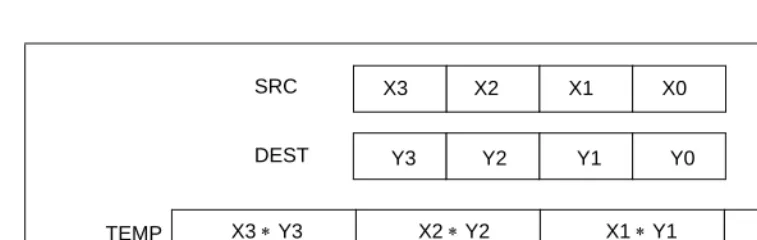
Converts packed signed word integers into packed signed byte integers (PACKSSWB) or converts packed signed doubleword integers into packed signed word integers (PACKSSDW), using saturation to handle overflow conditions. See Figure 4-1 for an example of the packing operation.
Opcode Instruction
64-Bit Mode
Compat/
Leg Mode Description
0F 63 /r PACKSSWB mm1, mm2/m64
Valid Valid Converts 4 packed signed word integers from mm1 and from
mm2/m64 into 8 packed signed byte integers in mm1 usingsigned saturation.
66 0F 63 /r PACKSSWB xmm1, xmm2/m128
Valid Valid Converts 8 packed signed word integers from xmm1 and from
xxm2/m128 into 16 packed signed byte integers in xxm1 usingsigned saturation.
0F 6B /r PACKSSDW mm1, mm2/m64
Valid Valid Converts 2 packed signed doubleword integers from mm1 and from mm2/m64 into 4 packed signed word integers in mm1 usingsigned saturation.
66 0F 6B /r PACKSSDW xmm1, xmm2/m128
Valid Valid Converts 4 packed signed
[image:25.612.50.426.416.508.2]doubleword integers from xmm1 and from xxm2/m128 into 8 packed signed word integers in xxm1 using signed saturation.
Figure 4-1. Operation of the PACKSSDW Instruction Using 64-bit Operands
D C
64-Bit SRC
64-Bit DEST
D’ C’ B’ A’
64-Bit DEST
4-22 Vol. 2B PACKSSWB/PACKSSDW—Pack with Signed Saturation The PACKSSWB instruction converts 4 or 8 signed word integers from the destination operand (first operand) and 4 or 8 signed word integers from the source operand (second operand) into 8 or 16 signed byte integers and stores the result in the destination operand. If a signed word integer value is beyond the range of a signed byte integer (that is, greater than 7FH for a positive integer or greater than 80H for a negative integer), the saturated signed byte integer value of 7FH or 80H, respectively, is stored in the destination.
The PACKSSDW instruction packs 2 or 4 signed doublewords from the destination operand (first operand) and 2 or 4 signed doublewords from the source operand (second operand) into 4 or 8 signed words in the destination operand (see Figure 4-1). If a signed doubleword integer value is beyond the range of a signed word (that is, greater than 7FFFH for a positive integer or greater than 8000H for a negative integer), the saturated signed word integer value of 7FFFH or 8000H, respectively, is stored into the destination.
The PACKSSWB and PACKSSDW instructions operate on either 64-bit or 128-bit operands. When operating on 64-bit operands, the destination operand must be an MMX technology register and the source operand can be either an MMX technology register or a 64-bit memory location. When operating on 128-bit operands, the destination operand must be an XMM register and the source operand can be either an XMM register or a 128-bit memory location.
In 64-bit mode, using an REX prefix in the form of REX.R permits this instruction to access additional registers (XMM8-XMM15).
Operation
PACKSSWB instruction with 64-bit operands:
DEST[7:0] ← SaturateSignedWordToSignedByte DEST[15:0]; DEST[15:8] ← SaturateSignedWordToSignedByte DEST[31:16]; DEST[23:16] ← SaturateSignedWordToSignedByte DEST[47:32]; DEST[31:24] ← SaturateSignedWordToSignedByte DEST[63:48]; DEST[39:32] ← SaturateSignedWordToSignedByte SRC[15:0]; DEST[47:40] ← SaturateSignedWordToSignedByte SRC[31:16]; DEST[55:48] ← SaturateSignedWordToSignedByte SRC[47:32]; DEST[63:56] ← SaturateSignedWordToSignedByte SRC[63:48]; PACKSSDW instruction with 64-bit operands:
DEST[15:0] ← SaturateSignedDoublewordToSignedWord DEST[31:0]; DEST[31:16] ← SaturateSignedDoublewordToSignedWord DEST[63:32]; DEST[47:32] ← SaturateSignedDoublewordToSignedWord SRC[31:0]; DEST[63:48] ← SaturateSignedDoublewordToSignedWord SRC[63:32]; PACKSSWB instruction with 128-bit operands:
Vol. 2B 4-23 PACKSSWB/PACKSSDW—Pack with Signed Saturation
DEST[71:64] ← SaturateSignedWordToSignedByte (SRC[15:0]); DEST[79:72] ← SaturateSignedWordToSignedByte (SRC[31:16]); DEST[87:80] ← SaturateSignedWordToSignedByte (SRC[47:32]); DEST[95:88] ← SaturateSignedWordToSignedByte (SRC[63:48]); DEST[103:96] ← SaturateSignedWordToSignedByte (SRC[79:64]); DEST[111:104] ← SaturateSignedWordToSignedByte (SRC[95:80]); DEST[119:112] ← SaturateSignedWordToSignedByte (SRC[111:96]); DEST[127:120] ← SaturateSignedWordToSignedByte (SRC[127:112]); PACKSSDW instruction with 128-bit operands:
DEST[15:0] ← SaturateSignedDwordToSignedWord (DEST[31:0]); DEST[31:16] ← SaturateSignedDwordToSignedWord (DEST[63:32]); DEST[47:32] ← SaturateSignedDwordToSignedWord (DEST[95:64]); DEST[63:48] ← SaturateSignedDwordToSignedWord (DEST[127:96]); DEST[79:64] ← SaturateSignedDwordToSignedWord (SRC[31:0]); DEST[95:80] ← SaturateSignedDwordToSignedWord (SRC[63:32]); DEST[111:96] ← SaturateSignedDwordToSignedWord (SRC[95:64]); DEST[127:112] ← SaturateSignedDwordToSignedWord (SRC[127:96]);
Intel C/C++ Compiler Intrinsic Equivalents
PACKSSWB __m64 _mm_packs_pi16(__m64 m1, __m64 m2) PACKSSDW __m64 _mm_packs_pi32 (__m64 m1, __m64 m2)
Flags Affected
None.
Protected Mode Exceptions
#GP(0) If a memory operand effective address is outside the CS, DS, ES, FS, or GS segment limit.
(128-bit operations only) If a memory operand is not aligned on a 16-byte boundary, regardless of segment.
#SS(0) If a memory operand effective address is outside the SS segment limit.
#UD If CR0.EM[bit 2] = 1.
(128-bit operations only) If CR4.OSFXSR[bit 9] = 0.
#NM If CR0.TS[bit 3] = 1.
#MF (64-bit operations only) If there is a pending x87 FPU exception.
#PF(fault-code) If a page fault occurs.
4-24 Vol. 2B PACKSSWB/PACKSSDW—Pack with Signed Saturation
Real-Address Mode Exceptions
#GP(0) (128-bit operations only) If a memory operand is not aligned on a 16-byte boundary, regardless of segment.
If any part of the operand lies outside of the effective address space from 0 to FFFFH.
#UD If CR0.EM[bit 2] = 1.
(128-bit operations only) If CR4.OSFXSR[bit 9] = 0.
#NM If CR0.TS[bit 3] = 1.
#MF (64-bit operations only) If there is a pending x87 FPU exception.
Virtual-8086 Mode Exceptions
Same exceptions as in Real Address Mode
#PF(fault-code) For a page fault.
#AC(0) (64-bit operations only) If alignment checking is enabled and an unaligned memory reference is made.
Compatibility Mode Exceptions
Same as for protected mode exceptions.
64-Bit Mode Exceptions
#SS(0) If a memory address referencing the SS segment is in a non-canonical form.
#GP(0) If the memory address is in a non-canonical form.
(128-bit operations only) If memory operand is not aligned on a 16-byte boundary, regardless of segment.
#UD If CR0.EM[bit 2] = 1.
(128-bit operations only) If CR4.OSFXSR[bit 9] = 0.
(128-bit operations only) If CPUID.01H:EDX.SSE2[bit 26] = 0.
#NM If CR0.TS[bit 3] = 1.
#MF (64-bit operations only) If there is a pending x87 FPU exception.
#PF(fault-code) If a page fault occurs.
Vol. 2B 4-25 PACKUSWB—Pack with Unsigned Saturation
PACKUSWB—Pack with Unsigned Saturation
Description
Converts 4 or 8 signed word integers from the destination operand (first operand) and 4 or 8 signed word integers from the source operand (second operand) into 8 or 16 unsigned byte inte-gers and stores the result in the destination operand. (See Figure 4-1 for an example of the packing operation.) If a signed word integer value is beyond the range of an unsigned byte integer (that is, greater than FFH or less than 00H), the saturated unsigned byte integer value of FFH or 00H, respectively, is stored in the destination.
The PACKUSWB instruction operates on either 64-bit or 128-bit operands. When operating on 64-bit operands, the destination operand must be an MMX technology register and the source operand can be either an MMX technology register or a 64-bit memory location. When oper-ating on 128-bit operands, the destination operand must be an XMM register and the source operand can be either an XMM register or a 128-bit memory location.
In 64-bit mode, using an REX prefix in the form of REX.R permits this instruction to access additional registers (XMM8-XMM15).
Operation
PACKUSWB instruction with 64-bit operands:
DEST[7:0] ← SaturateSignedWordToUnsignedByte DEST[15:0]; DEST[15:8] ← SaturateSignedWordToUnsignedByte DEST[31:16]; DEST[23:16] ← SaturateSignedWordToUnsignedByte DEST[47:32]; DEST[31:24] ← SaturateSignedWordToUnsignedByte DEST[63:48]; DEST[39:32] ← SaturateSignedWordToUnsignedByte SRC[15:0]; DEST[47:40] ← SaturateSignedWordToUnsignedByte SRC[31:16]; DEST[55:48] ← SaturateSignedWordToUnsignedByte SRC[47:32]; DEST[63:56] ← SaturateSignedWordToUnsignedByte SRC[63:48]; PACKUSWB instruction with 128-bit operands:
DEST[7:0] ← SaturateSignedWordToUnsignedByte (DEST[15:0]); DEST[15:8] ← SaturateSignedWordToUnsignedByte (DEST[31:16]); DEST[23:16] ← SaturateSignedWordToUnsignedByte (DEST[47:32]); Opcode Instruction
64-Bit Mode
Compat/
Leg Mode Description
0F 67 /r PACKUSWB mm, mm/m64
Valid Valid Converts 4 signed word integers from mm and 4 signed word integers from mm/m64 into 8 unsigned byte integers in mm using unsigned saturation.
66 0F 67 /r PACKUSWB xmm1,
xmm2/m128
Valid Valid Converts 8 signed word integers from xmm1 and 8 signed word integers from xmm2/m128 into 16 unsigned byte integers in xmm1
4-26 Vol. 2B PACKUSWB—Pack with Unsigned Saturation
DEST[31:24] ← SaturateSignedWordToUnsignedByte (DEST[63:48]); DEST[39:32] ← SaturateSignedWordToUnsignedByte (DEST[79:64]); DEST[47:40] ← SaturateSignedWordToUnsignedByte (DEST[95:80]); DEST[55:48] ← SaturateSignedWordToUnsignedByte (DEST[111:96]); DEST[63:56] ← SaturateSignedWordToUnsignedByte (DEST[127:112]); DEST[71:64] ← SaturateSignedWordToUnsignedByte (SRC[15:0]); DEST[79:72] ← SaturateSignedWordToUnsignedByte (SRC[31:16]); DEST[87:80] ← SaturateSignedWordToUnsignedByte (SRC[47:32]); DEST[95:88] ← SaturateSignedWordToUnsignedByte (SRC[63:48]); DEST[103:96] ← SaturateSignedWordToUnsignedByte (SRC[79:64]); DEST[111:104] ← SaturateSignedWordToUnsignedByte (SRC[95:80]); DEST[119:112] ← SaturateSignedWordToUnsignedByte (SRC[111:96]); DEST[127:120] ← SaturateSignedWordToUnsignedByte (SRC[127:112]);
Intel C/C++ Compiler Intrinsic Equivalent
PACKUSWB __m64 _mm_packs_pu16(__m64 m1, __m64 m2)
Flags Affected
None.
Protected Mode Exceptions
#GP(0) If a memory operand effective address is outside the CS, DS, ES, FS, or GS segment limit.
(128-bit operations only) If a memory operand is not aligned on a 16-byte boundary, regardless of segment.
#SS(0) If a memory operand effective address is outside the SS segment limit.
#UD If CR0.EM[bit 2] = 1.
128-bit operations will generate #UD only if CR4.OSFXSR[bit 9] = 0. Execution of 128-bit instructions on a non-SSE2 capable processor (one that is MMX technology capable) will result in the instruction operating on the mm registers, not #UD.
#NM If CR0.TS[bit 3] = 1.
#MF (64-bit operations only) If there is a pending x87 FPU exception.
#PF(fault-code) If a page fault occurs.
Vol. 2B 4-27 PACKUSWB—Pack with Unsigned Saturation
Real-Address Mode Exceptions
#GP(0) (128-bit operations only) If a memory operand is not aligned on a 16-byte boundary, regardless of segment.
If any part of the operand lies outside of the effective address space from 0 to FFFFH.
#UD If CR0.EM[bit 2] = 1.
128-bit operations will generate #UD only if CR4.OSFXSR[bit 9] = 0. Execution of 128-bit instructions on a non-SSE2 capable processor (one that is MMX technology capable) will result in the instruction operating on the mm registers, not #UD.
#NM If CR0.TS[bit 3] = 1.
#MF (64-bit operations only) If there is a pending x87 FPU exception.
Virtual-8086 Mode Exceptions
Same exceptions as in Real Address Mode
#PF(fault-code) For a page fault.
#AC(0) (64-bit operations only) If alignment checking is enabled and an unaligned memory reference is made.
Compatibility Mode Exceptions
4-28 Vol. 2B PACKUSWB—Pack with Unsigned Saturation
64-Bit Mode Exceptions
#SS(0) If a memory address referencing the SS segment is in a non-canonical form.
#GP(0) If the memory address is in a non-canonical form.
(128-bit operations only) If memory operand is not aligned on a 16-byte boundary, regardless of segment.
#UD If CR0.EM[bit 2] = 1.
(128-bit operations only) If CR4.OSFXSR[bit 9] = 0.
(128-bit operations only) If CPUID.01H:EDX.SSE2[bit 26] = 0.
#NM If CR0.TS[bit 3] = 1.
#MF (64-bit operations only) If there is a pending x87 FPU exception.
#PF(fault-code) If a page fault occurs.
Vol. 2B 4-29 PADDB/PADDW/PADDD—Add Packed Integers
PADDB/PADDW/PADDD—Add Packed Integers
Description
Performs an SIMD add of the packed integers from the source operand (second operand) and the destination operand (first operand), and stores the packed integer results in the destination operand. See Figure 9-4 in the IA-32 Intel Architecture Software Developer’s Manual, Volume 1
for an illustration of an SIMD operation. Overflow is handled with wraparound, as described in the following paragraphs.
These instructions can operate on either 64-bit or 128-bit operands. When operating on 64-bit operands, the destination operand must be an MMX technology register and the source operand can be either an MMX technology register or a 64-bit memory location. When operating on 128-bit operands, the destination operand must be an XMM register and the source operand can be either an XMM register or a 128-bit memory location.
The PADDB instruction adds packed byte integers. When an individual result is too large to be represented in 8 bits (overflow), the result is wrapped around and the low 8 bits are written to the destination operand (that is, the carry is ignored).
The PADDW instruction adds packed word integers. When an individual result is too large to be represented in 16 bits (overflow), the result is wrapped around and the low 16 bits are written to the destination operand.
The PADDD instruction adds packed doubleword integers. When an individual result is too large to be represented in 32 bits (overflow), the result is wrapped around and the low 32 bits are written to the destination operand.
Note that the PADDB, PADDW, and PADDD instructions can operate on either unsigned or signed (two's complement notation) packed integers; however, it does not set bits in the EFLAGS register to indicate overflow and/or a carry. To prevent undetected overflow condi-tions, software must control the ranges of values operated on.
Opcode Instruction
64-Bit Mode
Compat/
Leg Mode Description
0F FC /r PADDB mm, mm/m64
Valid Valid Add packed byte integers from mm/m64
and mm. 66 0F FC /r PADDB xmm1,
xmm2/m128
Valid Valid Add packed byte integers from
xmm2/m128 and xmm1. 0F FD /r PADDW mm,
mm/m64
Valid Valid Add packed word integers from
mm/m64 and mm. 66 0F FD /r PADDW xmm1,
xmm2/m128
Valid Valid Add packed word integers from
xmm2/m128 and xmm1. 0F FE /r PADDD mm,
mm/m64
Valid Valid Add packed doubleword integers from
mm/m64 and mm. 66 0F FE /r PADDD xmm1,
xmm2/m128
Valid Valid Add packed doubleword integers from
4-30 Vol. 2B PADDB/PADDW/PADDD—Add Packed Integers In 64-bit mode, using an REX prefix in the form of REX.R permits this instruction to access additional registers (XMM8-XMM15).
Operation
PADDB instruction with 64-bit operands: DEST[7:0] ← DEST[7:0] + SRC[7:0];
(* Repeat add operation for 2nd through 7th byte *) DEST[63:56] ← DEST[63:56] + SRC[63:56]; PADDB instruction with 128-bit operands:
DEST[7:0] ← DEST[7:0] + SRC[7:0];
(* Repeat add operation for 2nd through 14th byte *) DEST[127:120] ← DEST[111:120] + SRC[127:120]; PADDW instruction with 64-bit operands:
DEST[15:0] ← DEST[15:0] + SRC[15:0]; (* Repeat add operation for 2nd and 3th word *) DEST[63:48] ← DEST[63:48] + SRC[63:48]; PADDW instruction with 128-bit operands:
DEST[15:0] ← DEST[15:0] + SRC[15:0];
(* Repeat add operation for 2nd through 7th word *) DEST[127:112] ← DEST[127:112] + SRC[127:112]; PADDD instruction with 64-bit operands:
DEST[31:0] ← DEST[31:0] + SRC[31:0]; DEST[63:32] ← DEST[63:32] + SRC[63:32]; PADDD instruction with 128-bit operands:
DEST[31:0] ← DEST[31:0] + SRC[31:0];
(* Repeat add operation for 2nd and 3th doubleword *) DEST[127:96] ← DEST[127:96] + SRC[127:96];
Intel C/C++ Compiler Intrinsic Equivalents
PADDB __m64 _mm_add_pi8(__m64 m1, __m64 m2) PADDB __m128i_mm_add_epi8 (__m128ia,__m128ib ) PADDW __m64 _mm_addw_pi16(__m64 m1, __m64 m2) PADDW __m128i _mm_add_epi16 ( __m128i a, __m128i b) PADDD __m64 _mm_add_pi32(__m64 m1, __m64 m2) PADDD __m128i _mm_add_epi32 ( __m128i a, __m128i b)
Flags Affected
Vol. 2B 4-31 PADDB/PADDW/PADDD—Add Packed Integers
Protected Mode Exceptions
#GP(0) If a memory operand effective address is outside the CS, DS, ES, FS, or GS segment limit.
(128-bit operations only) If a memory operand is not aligned on a 16-byte boundary, regardless of segment.
#SS(0) If a memory operand effective address is outside the SS segment limit.
#UD If CR0.EM[bit 2] = 1.
128-bit operations will generate #UD only if CR4.OSFXSR[bit 9] = 0. Execution of 128-bit instructions on a non-SSE2 capable processor (one that is MMX technology capable) will result in the instruction operating on the mm registers, not #UD.
#NM If CR0.TS[bit 3] = 1.
#MF (64-bit operations only) If there is a pending x87 FPU exception.
#PF(fault-code) If a page fault occurs.
#AC(0) (64-bit operations only) If alignment checking is enabled and an unaligned memory reference is made while the current privilege level is 3.
Real-Address Mode Exceptions
#GP(0) (128-bit operations only) If a memory operand is not aligned on a 16-byte boundary, regardless of segment.
If any part of the operand lies outside of the effective address space from 0 to FFFFH.
#UD If CR0.EM[bit 2] = 1.
128-bit operations will generate #UD only if CR4.OSFXSR[bit 9] = 0. Execution of 128-bit instructions on a non-SSE2 capable processor (one that is MMX technology capable) will result in the instruction operating on the mm registers, not #UD.
#NM If CR0.TS[bit 3] = 1.
#MF (64-bit operations only) If there is a pending x87 FPU exception.
Virtual-8086 Mode Exceptions
Same exceptions as in Real Address Mode
#PF(fault-code) For a page fault.
4-32 Vol. 2B PADDB/PADDW/PADDD—Add Packed Integers
Compatibility Mode Exceptions
Same as for protected mode exceptions.
64-Bit Mode Exceptions
#SS(0) If a memory address referencing the SS segment is in a non-canonical form.
#GP(0) If the memory address is in a non-canonical form.
(128-bit operations only) If memory operand is not aligned on a 16-byte boundary, regardless of segment.
#UD If CR0.EM[bit 2] = 1.
(128-bit operations only) If CR4.OSFXSR[bit 9] = 0.
(128-bit operations only) If CPUID.01H:EDX.SSE2[bit 26] = 0.
#NM If CR0.TS[bit 3] = 1.
#MF (64-bit operations only) If there is a pending x87 FPU exception.
#PF(fault-code) If a page fault occurs.
Vol. 2B 4-33 PADDQ—Add Packed Quadword Integers
PADDQ—Add Packed Quadword Integers
Description
Adds the first operand (destination operand) to the second operand (source operand) and stores the result in the destination operand. The source operand can be a quadword integer stored in an MMX technology register or a 64-bit memory location, or it can be two packed quadword inte-gers stored in an XMM register or an 128-bit memory location. The destination operand can be a quadword integer stored in an MMX technology register or two packed quadword integers stored in an XMM register. When packed quadword operands are used, an SIMD add is performed. When a quadword result is too large to be represented in 64 bits (overflow), the result is wrapped around and the low 64 bits are written to the destination element (that is, the carry is ignored).
Note that the PADDQ instruction can operate on either unsigned or signed (two’s complement notation) integers; however, it does not set bits in the EFLAGS register to indicate overflow and/or a carry. To prevent undetected overflow conditions, software must control the ranges of the values operated on.
In 64-bit mode, using an REX prefix in the form of REX.R permits this instruction to access additional registers (XMM8-XMM15).
Operation
PADDQ instruction with 64-Bit operands: DEST[63:0] ← DEST[63:0] + SRC[63:0]; PADDQ instruction with 128-Bit operands:
DEST[63:0] ← DEST[63:0] + SRC[63:0]; DEST[127:64] ← DEST[127:64] + SRC[127:64];
Intel C/C++ Compiler Intrinsic Equivalents
PADDQ __m64 _mm_add_si64 (__m64 a, __m64 b) PADDQ __m128i _mm_add_epi64 ( __m128i a, __m128i b)
Flags Affected
None.
Opcode Instruction
64-Bit Mode
Compat/
Leg Mode Description
0F D4 /r PADDQ mm1, mm2/m64
Valid Valid Add quadword integer
mm2/m64 to mm1.
66 0F D4 /r PADDQ xmm1, xmm2/m128
Valid Valid Add packed quadword integers
4-34 Vol. 2B PADDQ—Add Packed Quadword Integers
Numeric Exceptions
None.
Protected Mode Exceptions
#GP(0) If a memory operand effective address is outside the CS, DS, ES, FS, or GS segment limit.
(128-bit operations only) If a memory operand is not aligned on a 16-byte boundary, regardless of segment.
#SS(0) If a memory operand effective address is outside the SS segment limit.
#UD If CR0.EM[bit 2] = 1.
(128-bit operations only) If CR4.OSFXSR[bit 9] = 0.
If CPUID.01H:EDX.SSE2[bit 26] = 0.
#NM If CR0.TS[bit 3] = 1.
#MF (64-bit operations only) If there is a pending x87 FPU exception.
#PF(fault-code) If a page fault occurs.
#AC(0) (64-bit operations only) If alignment checking is enabled and an unaligned memory reference is made while the current privilege level is 3.
Real-Address Mode Exceptions
#GP(0) (128-bit operations only) If a memory operand is not aligned on a 16-byte boundary, regardless of segment.
If any part of the operand lies outside of the effective address space from 0 to FFFFH.
#UD If CR0.EM[bit 2] = 1.
(128-bit operations only) If CR4.OSFXSR[bit 9] = 0.
If CPUID.01H:EDX.SSE2[bit 26] = 0.
#NM If CR0.TS[bit 3] = 1.
#MF (64-bit operations only) If there is a pending x87 FPU exception.
Virtual-8086 Mode Exceptions
Same exceptions as in Real Address Mode
#PF(fault-code) For a page fault.
Vol. 2B 4-35 PADDQ—Add Packed Quadword Integers
Compatibility Mode Exceptions
Same as for protected mode exceptions.
64-Bit Mode Exceptions
#SS(0) If a memory address referencing the SS segment is in a non-canonical form.
#GP(0) If the memory address is in a non-canonical form.
(128-bit operations only) If memory operand is not aligned on a 16-byte boundary, regardless of segment.
#UD If CR0.EM[bit 2] = 1.
(128-bit operations only) If CR4.OSFXSR[bit 9] = 0.
If CPUID.01H:EDX.SSE2[bit 26] = 0.
#NM If CR0.TS[bit 3] = 1.
#MF (64-bit operations only) If there is a pending x87 FPU exception.
#PF(fault-code) If a page fault occurs.
4-36 Vol. 2B PADDSB/PADDSW—Add Packed Signed Integers with Signed Saturation
PADDSB/PADDSW—Add Packed Signed Integers with Signed
Saturation
Description
Performs an SIMD add of the packed signed integers from the source operand (second operand) and the destination operand (first operand), and stores the packed integer results in the destina-tion operand. See Figure 9-4 in the IA-32 Intel Architecture Software Developer’s Manual, Volume 1 for an illustration of an SIMD operation. Overflow is handled with signed saturation, as described in the following paragraphs.
These instructions can operate on either 64-bit or 128-bit operands. When operating on 64-bit operands, the destination operand must be an MMX technology register and the source operand can be either an MMX technology register or a 64-bit memory location. When operating on 128-bit operands, the destination operand must be an XMM register and the source operand can be either an XMM register or a 128-bit memory location.
The PADDSB instruction adds packed signed byte integers. When an individual byte result is beyond the range of a signed byte integer (that is, greater than 7FH or less than 80H), the satu-rated value of 7FH or 80H, respectively, is written to the destination operand.
The PADDSW instruction adds packed signed word integers. When an individual word result is beyond the range of a signed word integer (that is, greater than 7FFFH or less than 8000H), the saturated value of 7FFFH or 8000H, respectively, is written to the destination operand.
In 64-bit mode, using an REX prefix in the form of REX.R permits this instruction to access additional registers (XMM8-XMM15).
Opcode Instruction
64-Bit Mode
Compat/
Leg Mode Description
0F EC /r PADDSB mm, mm/m64
Valid Valid Add packed signed byte integers from mm/m64 and mm and saturate the results. 66 0F EC /r PADDSB xmm1,
xmm2/m128
Valid Valid Add packed signed byte integers from xmm2/m128 and xmm1
saturate the results. 0F ED /r PADDSW mm,
mm/m64
Valid Valid Add packed signed word integers from mm/m64 and mm and saturate the results. 66 0F ED /r PADDSW xmm1,
xmm2/m128
Vol. 2B 4-37 PADDSB/PADDSW—Add Packed Signed Integers with Signed
Saturation
Operation
PADDSB instruction with 64-bit operands:
DEST[7:0] ← SaturateToSignedByte(DEST[7:0] + SRC (7:0]); (* Repeat add operation for 2nd through 7th bytes *)
DEST[63:56] ← SaturateToSignedByte(DEST[63:56] + SRC[63:56] ); PADDSB instruction with 128-bit operands:
DEST[7:0] ←SaturateToSignedByte (DEST[7:0] + SRC[7:0]); (* Repeat add operation for 2nd through 14th bytes *)
DEST[127:120] ← SaturateToSignedByte (DEST[111:120] + SRC[127:120]); PADDSW instruction with 64-bit operands
DEST[15:0] ← SaturateToSignedWord(DEST[15:0] + SRC[15:0] ); (* Repeat add operation for 2nd and 7th words *)
DEST[63:48] ← SaturateToSignedWord(DEST[63:48] + SRC[63:48] ); PADDSW instruction with 128-bit operands
DEST[15:0] ← SaturateToSignedWord (DEST[15:0] + SRC[15:0]); (* Repeat add operation for 2nd through 7th words *)
DEST[127:112] ← SaturateToSignedWord (DEST[127:112] + SRC[127:112]);
Intel C/C++ Compiler Intrinsic Equivalents
PADDSB __m64 _mm_adds_pi8(__m64 m1, __m64 m2) PADDSB __m128i _mm_adds_epi8 ( __m128i a, __m128i b) PADDSW __m64 _mm_adds_pi16(__m64 m1, __m64 m2) PADDSW __m128i _mm_adds_epi16 ( __m128i a, __m128i b)
Flags Affected
None.
Protected Mode Exceptions
#GP(0) If a memory operand effective address is outside the CS, DS, ES, FS, or GS segment limit.
(128-bit operations only) If a memory operand is not aligned on a 16-byte boundary, regardless of segment.
#SS(0) If a memory operand effective address is outside the SS segment limit.
#UD If CR0.EM[bit 2] = 1.
128-bit operations will generate #UD only if CR4.OSFXSR[bit 9] = 0. Execution of 128-bit instructions on a non-SSE2 capable processor (one that is MMX technology capable) will result in the instruction operating on the mm registers, not #UD.
4-38 Vol. 2B PADDSB/PADDSW—Add Packed Signed Integers with Signed Saturation #MF (64-bit operations only) If there is a pending x87 FPU exception.
#PF(fault-code) If a page fault occurs.
#AC(0) (64-bit operations only) If alignment checking is enabled and an unaligned memory reference is made while the current privilege level is 3.
Real-Address Mode Exceptions
#GP(0) (128-bit operations only) If a memory operand is not aligned on a 16-byte boundary, regardless of segment.
If any part of the operand lies outside of the effective address space from 0 to FFFFH.
#UD If CR0.EM[bit 2] = 1.
128-bit operations will generate #UD only if CR4.OSFXSR[bit 9] = 0. Execution of 128-bit instructions on a non-SSE2 capable processor (one that is MMX technology capable) will result in the instruction operating on the mm registers, not #UD.
#NM If CR0.TS[bit 3] = 1.
#MF (64-bit operations only) If there is a pending x87 FPU exception.
Virtual-8086 Mode Exceptions
Same exceptions as in Real Address Mode
#PF(fault-code) For a page fault.
#AC(0) (64-bit operations only) If alignment checking is enabled and an unaligned memory reference is made.
Compatibility Mode Exceptions
Same as for protected mode exceptions.
64-Bit Mode Exceptions
#SS(0) If a memory address referencing the SS segment is in a non-canonical form.
#GP(0) If the memory address is in a non-canonical form.
(128-bit operations only) If memory operand is not aligned on a 16-byte boundary, regardless of segment.
#UD If CR0.EM[bit 2] = 1.
(128-bit operations only) If CR4.OSFXSR[bit 9] = 0.
Vol. 2B 4-39 PADDSB/PADDSW—Add Packed Signed Integers with Signed
Saturation
#NM If CR0.TS[bit 3] = 1.
#MF (64-bit operations only) If there is a pending x87 FPU exception.
#PF(fault-code) If a page fault occurs.
4-40 Vol. 2B PADDUSB/PADDUSW—Add Packed Unsigned Integers with Unsigned Saturation
PADDUSB/PADDUSW—Add Packed Unsigned Integers with
Unsigned Saturation
Description
Performs an SIMD add of the packed unsigned integers from the source operand (second operand) and the destination operand (first operand), and stores the packed integer results in the destination operand. See Figure 9-4 in the IA-32 Intel Architecture Software Developer’s Manual, Volume 1 for an illustration of an SIMD operation. Overflow is handled with unsigned saturation, as described in the following paragraphs.
These instructions can operate on either 64-bit or 128-bit operands. When operating on 64-bit operands, the destination operand must be an MMX technology register and the source operand can be either an MMX technology register or a 64-bit memory location. When operating on 128-bit operands, the destination operand must be an XMM register and the source operand can be either an XMM register or a 128-bit memory location.
The PADDUSB instruction adds packed unsigned byte integers. When an individual byte result is beyond the range of an unsigned byte integer (that is, greater than FFH), the saturated value of FFH is written to the destination operand.
The PADDUSW instruction adds packed unsigned word integers. When an individual word result is beyond the range of an unsigned word integer (that is, greater than FFFFH), the satu-rated value of FFFFH is written to the destination operand.
In 64-bit mode, using an REX prefix in the form of REX.R permits this instruction to access additional registers (XMM8-XMM15).
Opcode Instruction
64-Bit Mode
Compat/
Leg Mode Description
0F DC /r PADDUSB mm, mm/m64
Valid Valid Add packed unsigned byte integers from mm/m64 and mm and saturate the results.
66 0F DC /r PADDUSB xmm1, xmm2/m128
Valid Valid Add packed unsigned byte integers from xmm2/m128 and xmm1
saturate the results. 0F DD /r PADDUSW mm,
mm/m64
Valid Valid Add packed unsigned word integers from mm/m64 and mm and saturate the results.
66 0F DD /r PADDUSW xmm1, xmm2/m128
Vol. 2B 4-41 PADDUSB/PADDUSW—Add Packed Unsigned Integers with Unsigned
Saturation
Operation
PADDUSB instruction with 64-bit operands:
DEST[7:0] ← SaturateToUnsignedByte(DEST[7:0] + SRC (7:0] ); (* Repeat add operation for 2nd through 7th bytes *)
DEST[63:56] ← SaturateToUnsignedByte(DEST[63:56] + SRC[63:56] PADDUSB instruction with 128-bit operands:
DEST[7:0] ← SaturateToUnsignedByte (DEST[7:0] + SRC[7:0]); (* Repeat add operation for 2nd through 14th bytes *)
DEST[127:120] ← SaturateToUnSignedByte (DEST[127:120] +SRC[127:120]); PADDUSW instruction with 64-bit operands:
DEST[15:0] ← SaturateToUnsignedWord(DEST[15:0] + SRC[15:0] ); (* Repeat add operation for 2nd and 3rd words *)
DEST[63:48] ← SaturateToUnsignedWord(DEST[63:48] + SRC[63:48] ); PADDUSW instruction with 128-bit operands:
DEST[15:0] ← SaturateToUnsignedWord (DEST[15:0] + SRC[15:0]); (* Repeat add operation for 2nd through 7th words *)
DEST[127:112] ← SaturateToUnSignedWord (DEST[127:112] + SRC[127:112]);
Intel C/C++ Compiler Intrinsic Equivalents
PADDUSB __m64 _mm_adds_pu8(__m64 m1, __m64 m2) PADDUSW __m64 _mm_adds_pu16(__m64 m1, __m64 m2) PADDUSB __m128i _mm_adds_epu8 ( __m128i a, __m128i b) PADDUSW __m128i _mm_adds_epu16 ( __m128i a, __m128i b)
Flags Affected
None.
Numeric Exceptions
None.
Protected Mode Exceptions
#GP(0) If a memory operand effective address is outside the CS, DS, ES, FS, or GS segment limit.
(128-bit operations only) If a memory operand is not aligned on a 16-byte boundary, regardless of segment.
4-42 Vol. 2B PADDUSB/PADDUSW—Add Packed Unsigned Integers with Unsigned Saturation #UD If CR0.EM[bit 2] = 1.
128-bit operations will generate #UD only if CR4.OSFXSR[bit 9] = 0. Execution of 128-bit instructions on a non-SSE2 capable processor (one that is MMX technology capable) will result in the instruction operating on the mm registers, not #UD.
#NM If CR0.TS[bit 3] = 1.
#MF (64-bit operations only) If there is a pending x87 FPU exception.
#PF(fault-code) If a page fault occurs.
#AC(0) (64-bit operations only) If alignment checking is enabled and an unaligned memory reference is made while the current privilege level is 3.
Real-Address Mode Exceptions
#GP(0) (128-bit operations only) If a memory operand is not aligned on a 16-byte boundary, regardless of segment.
If any part of the operand lies outside of the effective address space from 0 to FFFFH.
#UD If CR0.EM[bit 2] = 1.
128-bit operations will generate #UD only if CR4.OSFXSR[bit 9] = 0. Execution of 128-bit instructions on a non-SSE2 capable processor (one that is MMX technology capable) will result in the instruction operating on the mm registers, not #UD.
#NM If CR0.TS[bit 3] = 1.
#MF (64-bit operations only) If there is a pending x87 FPU exception.
Virtual-8086 Mode Exceptions
Same exceptions as in Real Address Mode
#PF(fault-code) For a page fault.
#AC(0) (64-bit operations only) If alignment checking is enabled and an unaligned memory reference is made.
Compatibility Mode Exceptions
Vol. 2B 4-43 PADDUSB/PADDUSW—Add Packed Unsigned Integers with Unsigned
Saturation
64-Bit Mode Exceptions
#SS(0) If a memory address referencing the SS segment is in a non-canonical form.
#GP(0) If the memory address is in a non-canonical form.
(128-bit operations only) If memory operand is not aligned on a 16-byte boundary, regardless of segment.
#UD If CR0.EM[bit 2] = 1.
(128-bit operations only) If CR4.OSFXSR[bit 9] = 0.
(128-bit operations only) If CPUID.01H:EDX.SSE2[bit 26] = 0.
#NM If CR0.TS[bit 3] = 1.
#MF (64-bit operations only) If there is a pending x87 FPU exception.
#PF(fault-code) If a page fault occurs.
4-44 Vol. 2B PAND—Logical AND
PAND—Logical AND
Description
Performs a bitwise logical AND operation on the source operand (second operand) and the desti-nation operand (first operand) and stores the result in the destidesti-nation operand. The source operand can be an MMX technology register or a 64-bit memory location or it can be an XMM register or a 128-bit memory location. The destination operand can be an MMX technology register or an XMM register. Each bit of the result is set to 1 if the corresponding bits of the first and second operands are 1; otherwise, it is set to 0.
In 64-bit mode, using an REX prefix in the form of REX.R permits this instruction to access additional registers (XMM8-XMM15).
Operation
DEST ← (DEST AND SRC);
Intel C/C++ Compiler Intrinsic Equivalent
PAND __m64 _mm_and_si64 (__m64 m1, __m64 m2) PAND __m128i _mm_and_si128 ( __m128i a, __m128i b)
Flags Affected
None.
Numeric Exceptions
None.
Protected Mode Exceptions
#GP(0) If a memory operand effective address is outside the CS, DS, ES, FS, or GS segment limit.
(128-bit operations only) If a memory operand is not aligned on a 16-byte boundary, regardless of segment.
#SS(0) If a memory operand effective address is outside the SS segment limit.
Opcode Instruction
64-Bit Mode
Compat/
Leg Mode Description
0F DB /r PAND mm, mm/m64 Valid Valid Bitwise AND mm/m64 and
mm.
66 0F DB /r PAND xmm1, xmm2/m128 Valid Valid Bitwise AND of xmm2/m128
Vol. 2B 4-45 PAND—Logical AND
#UD If CR0.EM[bit 2] = 1.
128-bit operations will generate #UD only if CR4.OSFXSR[bit 9] = 0. Execution of 128-bit instructions on a non-SSE2 capable processor (one that is MMX technology capable) will result in the instruction operating on the mm registers, not #UD.
#NM If CR0.TS[bit 3] = 1.
#MF (64-bit operations only) If there is a pending x87 FPU exception.
#PF(fault-code) If a page fault occurs.
#AC(0) (64-bit operations only) If alignment checking is enabled and an unaligned memory reference is made while the current privilege level is 3.
Real-Address Mode Exceptions
#GP(0) (128-bit operations only) If a memory operand is not aligned on a 16-byte boundary, regardless of segment.
If any part of the operand lies outside of the effective address space from 0 to FFFFH.
#UD If CR0.EM[bit 2] = 1.
128-bit operations will generate #UD only if CR4.OSFXSR[bit 9] = 0. Execution of 128-bit instructions on a non-SSE2 capable processor (one that is MMX technology capable) will result in the instruction operating on the mm registers, not #UD.
#NM If CR0.TS[bit 3] = 1.
#MF (64-bit operations only) If there is a pending x87 FPU exception.
Virtual-8086 Mode Exceptions
Same exceptions as in Real Address Mode
#PF(fault-code) For a page fault.
#AC(0) (64-bit operations only) If alignment checking is enabled and an unaligned memory reference is made.
Compatibility Mode Exceptions
4-46 Vol. 2B PAND—Logical AND
64-Bit Mode Exceptions
#SS(0) If a memory address referencing the SS segment is in a non-canonical form.
#GP(0) If the memory address is in a non-canonical form.
(128-bit operations only) If memory operand is not aligned on a 16-byte boundary, regardless of segment.
#UD If CR0.EM[bit 2] = 1.
(128-bit operations only) If CR4.OSFXSR[bit 9] = 0.
(128-bit operations only) If CPUID.01H:EDX.SSE2[bit 26] = 0.
#NM If CR0.TS[bit 3] = 1.
#MF (64-bit operations only) If there is a pending x87 FPU exception.
#PF(fault-code) If a page fault occurs.
Vol. 2B 4-47 PANDN—Logical AND NOT
PANDN—Logical AND NOT
Description
Performs a bitwise logical NOT of the destination operand (first operand), then performs a bitwise logical AND of the source operand (second operand) and the inverted destin