Design of adaptable simulation models.
POHL, Thomas.
Available from Sheffield Hallam University Research Archive (SHURA) at:
http://shura.shu.ac.uk/20240/
This document is the author deposited version. You are advised to consult the publisher's version if you wish to cite from it.
Published version
POHL, Thomas. (2006). Design of adaptable simulation models. Doctoral, Sheffield Hallam University (United Kingdom)..
Copyright and re-use policy
See http://shura.shu.ac.uk/information.html
Adsetts Centre City Campus Sheffield S1 1WB
1 0 1 8 3 5 3 5 2 6
Return to Learning Centre of issue
Fines are charged at 50p per hour
- 7 AW ?no7
S p M
1 0 AUG
, 5
^ 7 AUG 2007
£L
—
- A OCT 2007
■ 4 - a o
2007
6pm
ProQuest Number: 10700885 All rights reserved INFORMATION TO ALL USERS
The quality of this reproduction is dependent upon the quality of the copy submitted. In the unlikely event that the author did not send a com plete manuscript and there are missing pages, these will be noted. Also, if material had to be removed,
a note will indicate the deletion.
uest
ProQuest 10700885
Published by ProQuest LLC(2017). Copyright of the Dissertation is held by the Author. All rights reserved.
This work is protected against unauthorized copying under Title 17, United States C ode Microform Edition © ProQuest LLC.
ProQuest LLC.
789 East Eisenhower Parkway P.O. Box 1346
Design of Adaptable Simulation Models
Thomas Pohl
A thesis submitted in partial fulfilment of the requirements of Sheffield Hallam University
for the degree of Doctor of Philosophy
Sheffield Hallam University Materials & Engineering Research Institute
The undersigned hereby certify that they have read and recommend to the Faculty of Arts, Computing, Engineering and Sciences for acceptance a thesis entitled “Design of Adaptable Simulation Models” by Thomas Pohl in partial fulfillment of the requirements for the degree of Doctor of Philosophy.
Dated: September 2006
Research Supervisors: ___________________________
Prof. Terrence Perera
Dr David Clegg
Examining Committee:_________________________
Dr Tillal Eldabi
Sheffield Hallam University
Date: September 2006
Author: Thomas Pohl
Title: Design of Adaptable Simulation Models Department: Materials & Engineering Research Institute Degree: Ph.D. Convocation: October Year: 2006
Permission is herewith granted to Sheffield Hallam University to circulate and to have copied for non-commercial purposes, at its discretion, the above title upon the request of individuals or institutions.
THE AUTHOR ATTESTS THAT PERMISSION HAS BEEN OBTAINED FOR THE USE OF ANY COPYRIGHTED MATERIAL APPEARING IN THIS THESIS (OTHER THAN BRIEF EXCERPTS REQUIRING ONLY PROPER ACKNOWLEDGEMENT IN SCHOLARLY WRITING) AND THAT ALL SUCH USE IS CLEARLY ACKNOWLEDGED.
Signature of Author
Contents
List of Tables viii
List of Figures ix
1 General Introduction 1
1.1 Background to research... 1
1.2 Justification for re se a rc h ... 2
1.3 Focus of research... 4
1.4 Outline of thesis... 4
1.4.1 Chapter 1 - Introduction... 4
1.4.2 Chapter 2 - Literature R eview ... 5
1.4.3 Chapter 3 - Research M ethodology... 5
1.4.4 Chapter 4 - Interviews and Questionnaire Survey... 5
1.4.5 Chapter 5 - Benchmarking... 5
1.4.6 Chapter 6 - Modified Model Building Guidelines... 5
1.4.7 Chapter 7 - Validation of the Guidelines... 5
1.4.8 Chapter 8 - Findings and C onclusion... 5
2 Literature Review 6 2.1 Introduction... 6
2.2 Definitions... 6
2.3 General principles... 7
2.3.1 LawandKelton... 7
2.3.2 Balci ... 10
2.3.3 Banks and Carson ... 13
2.3.4 Kelton, Sadowski and Sadow ski... 15
2.3.5 Benjamin etal... 16
2.3.7 Comparison of approaches... 19
2.4 Types of adaptability in Simulation M o d e ls ... 19
2.5 Adaptability of Simulation T ools... 23
2.5.1 Data-driven sim ulators... 23
2.5.2 Programming versus assembling... 24
2.5.3 Programming differences ... 25
2.5.4 Generic sim ulators... 26
2.5.5 Adaptable simulation models... 28
2.5.6 Other approaches... 30
2.5.7 Discussion of adaptability approaches... 31
2.6 Measuring adaptability... 33
2.7 Surveys on simulation software... 34
2.7.1 Previous su rv ey s... 34
2.7.2 Comparison of surveys... 36
2.8 Key findings ... 37
3 Research Methodology 39 3.1 Key Stages ... 39
3.2 Interviews/Questionnaire survey... 41
3.2.1 Interviews... 41
3.2.2 Questionnaire survey... 51
3.3 Benchmarking... 52
3.4 Experiments... 57
3.4.1 Controlled experiments... 57
3.4.2 Natural experiments ... 58
3.4.3 Observational studies... 58
3.4.4 Field experiments... 58
3.5 Justification for the methodologies u s e d ... 59
3.5.1 Interviews/ Questionnaire survey... 59
3.5.2 B enchm arking... 59
3.5.3 Experiments ... 60
4 Interviews and Questionnaire Survey 61 4.1 Interviews... 61
4.1.1 Reasons for interview questions... 61
4.2 Questionnaire Survey... 64
4.2.1 Questions — User background... 65
4.2.2 Questions — Main bloc ... 65
4.2.3 Results — User background... 66
4.2.4 Results — Main b lo c ... 68
4.3 Key F in d in g s... 73
4.3.1 Interviews... 73
4.3.2 Questionnaire Survey... 73
5 Benchmarking 74 5.1 Definitions... 74
5.2 Changes influencing the simulation m o d el... 75
5.3 Choice of so ftw are... 78
5.4 Conducting the benchm arking... 79
5.5 Organizational lay o u t... 82
5.6 Results overview ... 83
5.6.1 Package adaptability... 83
5.6.2 Results from the sixth biennial survey... 83
5.6.3 Overall adaptability... 84
5.6.4 Sequencing... 87
5.6.5 Organizational layout... 90
5.7 Key findings... 93
6 Modified Model Building Guidelines 94 6.1 An overview... 94
6.2 The guidelines in d etail... 99
6.2.1 Formulate problem and plan the stu d y ... 99
6.2.2 Identify potential future modifications... 99
6.2.3 Construct a computer program and v e rify ...100
6.2.4 Provisions for m odifications...100
6.2.5 Documentation, presentation and use of re s u lts ...101
6.3 Adaptability guidelines... 102
6.3.1 Sequencing...102
6.3.2 Model Layout... 103
6.3.3 A nnotation...104
7 Validation of the Guidelines 107
7.1 Validation interview s... 107
7.1.1 Interview questions... 107
7.1.2 Interview feedback... 109
7.2 Experim ent...110
7.2.1 Test g ro u p s... I ll 7.2.2 The m odels... I ll 7.3 Key findings...114
7.3.1 Interviews... 114
7.3.2 Experim ent...114
8 Findings and Conclusion 115 8.1 Interviews... 115
8.2 Questionnaire su rv e y ... 115
8.2.1 User related findings... 115
8.2.2 Main findings... 116
8.2.3 conclusion... 118
-8.3 Benchmarking...118
8.4 Modified model building guidelines... 119
8.5 Summary of conclusion... 120
8.6 Limitations and further w o rk ...122
References 124
A Interview Questions A
B Questionnaire Survey B
C Organizational Layout C
D Group Benchmarking Tasks D
E Validation Interview Questions E
F Experiment F
)
G Modified Model Building Guidelines G
List of Tables
3.1 Interview ty p e s ... 42
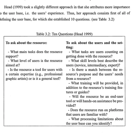
3.2 Ten Questions... 54
3.3 Grouping of benchmarking ty p es... 56
3.4 Situations for Research Strategies ... 57
4.1 Software ra n k in g ... 67
4.2 Difficulty in modifying elem ents... 69
4.3 Weighted difficulty ra tin g s ... 70
4.4 Difficulty in modifying a distribution and changing the data fo rm ... 71
4.5 Difficulty in adding and removing model d e ta il... 71
4.6 Frequency of modifying model logic and simulation code ... 71
4.7 Availability o f ‘undo’ and ‘redo’ options and of templates... 71
4.8 Usage of available tem plates... 71
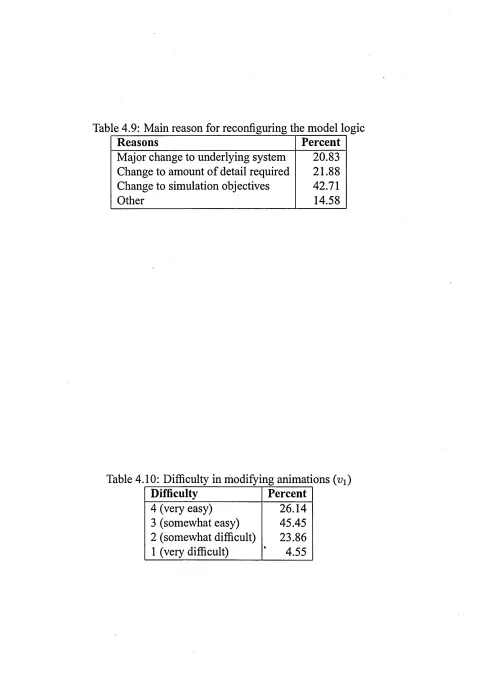
4.9 Main reason for reconfiguring the model lo g ic... 72
4.10 Difficulty in modifying animations... 72
5.1 6th biennial survey - results ... 84
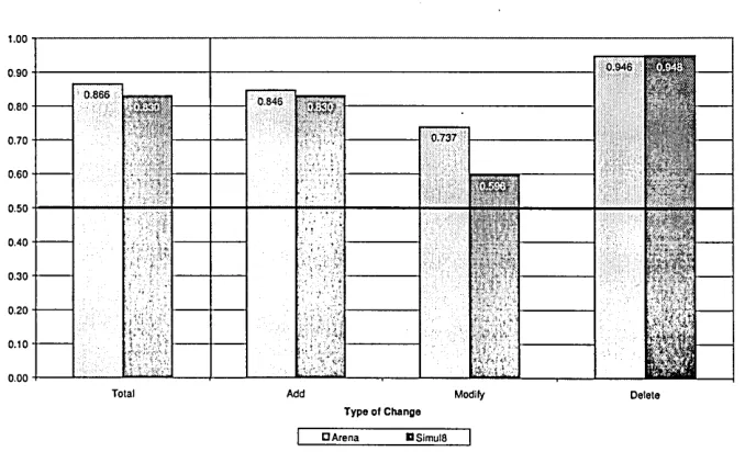
5.2 Adaptability values for Arena and S im u l8 ... 88
7.1 Adaptability factors ...113
List of Figures
2.1 Steps in a simulation s tu d y ... 9
2.2 The life cycle of a simulation study... 12
2.3 Steps in a simulation s tu d y ... 14
2.4 Phase stru c tu re ... 15
2.5 Separation of Levels ... 16
2.6 Simulation projects: an overview... 17
2.7 Flexibility facto rs... 21
3.1 Key stages - flo w ch art... 40
3.2 Simple structure... 48
3.3 Chain stru ctu re... 48
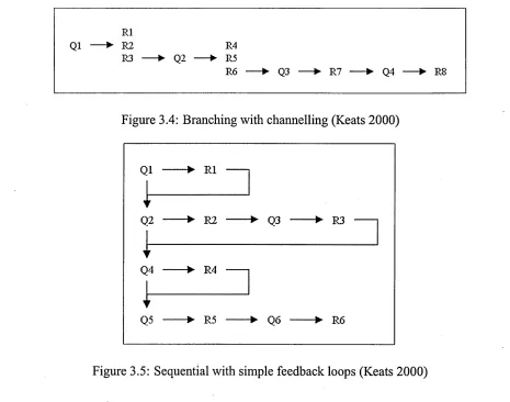
3.4 Branching with channeling... 49
3.5 Sequential with simple feedback lo o p s... 49
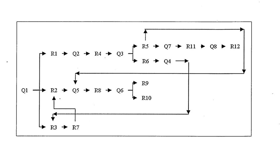
3.6 Branching with complex feedback lo o p s... 50
3.7 Constellated structure... 50
4.1 Overall model building experience... 66
4.2 Software ra n k in g ... 68
5.1 Basic model for benchmarking... 81
5.2 Adaptability without animation... 85
5.3 Adaptability with animation ... 86
5.4 Adaptability (with & without animation averaged)... 87
5.5 Influence of sequencing on adaptability ... 87
5.6 Adaptability of hard coding and sequencing by category ... 88
5.7 Adaptability coefficients... 89
5.8 Model anim ation... 90
5.9 Model logic with and without sub-m odels... 90
6.1 Modified model building guidelines... 98
6.2 Data placement m a trix ...105
7.1 Adaptability factors . . . ... 113
Abstract
In today’s world, with ever increasing competition, modelling and simulation proves to be a very helpful tool. Many methodologies exist to help build a simulation model from scratch. In terms of adaptability, most current attempts focus on either the operational side, ie the automated integration of data into a model, or the creation of new software. However, very few attempts are being made to improve the adaptability of shelved models built in existing simulation software. As a result, there is a certain reluctance, in some areas, to use simulation to its full potential.
Based on these facts, it is obvious that anything, which makes reuse of simulation models easier, can help improve the use and spread of simulation as a valuable tool to maintain a company’s competitiveness. In order to find such a solution, the following issues are looked at in this thesis: The changes to a simulation model that constitute the biggest problem, ways to minimise those changes, and possibilities to simplify the implementation of those changes.
Those factors are evaluated, first by investigating current practices of building adapt able simulation models via a literature review, then the most difficult changes to im plement in a simulation model, and the most frequent types of simulation software, are identified by means of interviews and questionnaire surveys. Next, parameters describ ing the adaptability of a simulation model are defined. In a further step, two of the most widely used simulation packages are benchmarked against a variety of tasks, reflecting the changes most frequent to models. The benchmarking study also serves to define and test certain elements regarding their suitability for adaptable models. Based on all those steps, model building guidelines for the creation of adaptable simulation models are developed and then validated by means of interviews and a framed field experiment.
Preface
This thesis is submitted to the Faculty of Arts, Computing, Engineering and Sciences of Sheffield Hallam University for the degree of Doctor of Philosophy
I would like to express my deepest gratitude and appreciation to my supervisors, Dr. Terrence Perera and Dr. David Clegg, for their guidance and constructive criticism during the course of this study. I would like to thank my family for their support. I would also like to thank Sue Raynor and all the administrative staff within the School of Engineering/ the Faculty of Arts, Computing, Engineering and Sciences for their help and support. My appreciation also extends to all those individuals who participated as interviewees in this study, especially Ruby Lau, Anna Lassila, Lionel Joseph and Claire Westby from Sheffield Hallam university, Edwin Valentin from Systems Navigator and the postgraduate students at the TU Delft in the Netherlands.
The results obtained during the course of this research are to the best of my knowledge original, except where reference is made to the work of others.
T. Pohl
Chapter 1
General Introduction
1.1 Background to research
With the increasing competition on the global market, companies are forced to gain an ad vantage over their competitors in order to stay successful. Customers, on the other hand, want to get the best possible product for the lowest price, thereby fuelling the competi tion among suppliers in their quest to produce the best possible product or service at the lowest price over all. In order to minimize their costs and thus gain and/or keep their com petitive advantage in applying economies of scale, or finding a niche market, or offering higher quality products/services, the companies turn to modelling. This means that mod elling is used as a tool to improve current processes or products/services. Simultaneously, simulation thus serves as a tool improve or maintain one’s competitive edge.
Modelling is a simple term that covers a huge domain. Architects use small-scale models of their creations to give their customers a clearer picture of what the finished building will look like. Aeronautics companies and car manufacturers use small-scale models to test their creations’ behaviour and influence on air currents. Physicists, as tronomers and mathematicians use mathematical models to describe their theories and findings. In fashion, human models are used to show the designers’ new creations to the interested public.
1.2 Justification for research
part would be too costly or impossible, such as in the design of a new aircraft wing. The second type of simulation is used in the design or modification of a process, be it in manufacturing or services, where the process does not exist yet, or where experimenting with the actual system would be too costly or difficult, e.g. when it would interfere with ongoing production.
While some simulation projects are of relatively short duration - days or weeks - and fairly simple, other simulations may have a much larger time frame. In the aeronautical industry, for example, where simulation is extensively used, a project, such as a new airplane, has a time frame of up to 30 or 40 years from the first concept. Such a project may start as a concept or study, then move on to the production of prototypes. Next, serial production starts and modifications to the plane may be introduced every few years as new technology becomes available. After production of the airplane as such stops, production of spare parts may still go on, as the existing aircraft have to be serviced until the airplane is phased out. Not only does such a project span over long time periods and consist of very diverse stages, such projects are also very complex due to their sheer size, the number of components, people and organisations involved.
Due to large projects undergoing different phases, any simulations used over the course of the project life cycle need to be adapted to those changes. In manufacturing for example, as new technology or a new machine is introduced to the plant, this change needs to be reflected in the simulation and the same goes for a change of goods produced.
1.2 Justification for research
Currently simulation models are mostly used on a one-off basis. As McLean and Leong (2002) pointed out, “simulations are often developed from scratch”. This means that models are constructed for a certain purpose, such as the design of new systems or the improvement of an existing one, and then discarded. Also, building a simulation model is a lengthy process. This is due to the need to analyse the existing system and/or to gather all the necessary data to build a valid, credible model.
1.2 Justification for research
occurring to the system over the course of the project as mentioned above, it becomes necessary for the simulation models to be adaptable. This means that there is a need to modify an existing simulation to fit a changed system and, most of all, a need to modify it so that it delivers usable answers to a new problem.
Another dimension of change within a model, even one for single-use, is that, as the understanding of the system under study improves and more data becomes available, this might also lead to a change of focus of the simulation study. The building of a simulation model, ie of its logic, generally starts before all necessary data have been gathered. As a result, the main goals of the simulation study are rather crude and get refined over time, as more and more data becomes available. However, this increase in knowledge and understanding of the system under study can make the original simulation objective obsolete, or reveal that it needs to be somewhat modified to gain or retain validity. As a result, changes within a single simulation model might need to be implemented by the analyst.
The need for adaptable simulation models is well recognized in literature.
McLean and Leong (2002) proposed a modularization of simulation models to help in that respect. Pidd (2002) suggested various reuse strategies. Reese and Wyatt (1987) defined software reuse as “the isolation, selection, maintenance, and use o f software components in the development and maintenance o f a software p r o je c tde Ruiter et al. (2000) sug gested a concept for an integrated simulator for recurring decisions, and
Herrmann et al. (2000) reviewed concepts of adaptability and put forth suggestions to measure this adaptability.
Hlupic (2000) conducted a survey on academic and industrial users of simulation soft ware in which she showed that more than half of academic and a quarter of industrial users had problems in modelling associated with a lack of adaptability and software limitations of the package used.
1.3 Focus of research
1.3 Focus of research
Although this need for adaptability has been recognised, the impact of a necessary change on the overall project has not been examined yet, nor what types of change constitute the biggest problem to the simulation expert.
From this, the following questions arose:
i What change or changes to a simulation project constitute the biggest problem,
at its implementation, for simulation software users?
ii How can those changes be minimized?
iii How can the implementation of changes to a simulation project be simplified?
Together, these questions form the basis for the research work proposing a novel de sign of adaptable simulation models in manufacturing, based on a widely used simulation package.
To this end, it was necessary to:
i Investigate current practices of building adaptable simulation models in industry ii Identify the most difficult and/or most frequent changes to implement in a simula
tion study, irrespective of the software used,
iii Identify parameters which describe the adaptability of simulation models
iv Conduct a benchmarking study of some of the leading simulation software packages towards their inbuilt adaptability
v Develop model building guidelines for the creation of adaptable simulation models vi Develop a prototype adaptable simulation model and validate its design.
1.4 Outline of thesis
This thesis is divided into 8 parts, consisting of a general introduction, a literature review, research methodology, development and conduct of the research, analysis of the results and a conclusion.
1.4.1 Chapter 1 - Introduction This chapter contains an introduction to the subject
1.4 Outline of thesis
1.4.2 Chapter 2 - Literature Review In the literature review, an overview of the subject area is given and the strengths and weaknesses of the referenced material are discussed. The questions arising from this analysis form the main research questions.
1.4.3 Chapter 3 - Research Methodology Chapter 3 reviews the methodologies used for the research. These include interviews, surveys, benchmark studies, action research and case studies.
1.4.4 Chapter 4 - Interviews and Questionnaire Survey This chapter gives an over view of the data generated by means of interviews and questionnaire surveys and how the research methodologies were put into practice to obtain that data. It also shows the data via the survey and the analysis thereof.
1.4.5 Chapter 5 - Benchmarking The chapter on benchmarking investigates the over all adaptability of two simulation packages and compares them to one another. Also, the extent to which the use of sub-models helps understanding a model is tested through benchmarking.
1.4.6 Chapter 6 - Modified Model Building Guidelines This chapter introduces a methodology specifically aimed at adaptable simulation models and their construction. This methodology is based on the results obtained from the preceding chapters.
1.4.7 Chapter 7 - Validation of the Guidelines In this chapter, the validation of the modified model building guidelines is looked at. For the validation, interviews and exper iments are used.
Chapter 2
Literature Review
This chapter investigates various theories on and approaches to model building, different types of adaptability generally encountered in simulation, along with their definitions. It also looks at the adaptability of simulation tools, how such adaptability can be measured and the status quo on surveys of simulation software.
2.1 Introduction
In this chapter, the current practices of building adaptable simulation models and, more generally, ways to render simulation models more adaptable and reusable are investigated. In a first part, an overview of general model building principles and practices as described in literature is given. This is important to help place changes to the modelling process in the right context. The second part focuses on the different approaches to aiding the simulation expert in making simulation models more adaptable and reusable.
2.2 Definitions
The New Shorter Oxford English Dictionary gives the following definitions:
2.3 General principles
• Simulation: ”1) The action or an act of simulating something; computing a model produced by this means” (The New Shorter Oxford English Dictionary).
In the context of this research, the term model refers to a simplified, conceptual repre sentation of a system or process used to gain a better understanding. And, as the def initions quoted above indicate, modelling in this case is the creation of a computerized representation of a simplified process or system for gaining theoretical and/or empirical understanding.
Banks and Carson (1984) defined simulation as “the imitation o f the operation o f a ,
real-world process or system over time. ... Simulation involves the generation o f an arti ficial history o f a system, and the observation o f that artificial history to draw inferences
concerning the operating characteristics o f the real system”
With their definition, Banks and Carson introduced another factor: time. Not only is time inherent to simulations, thus signifying constant change in the output of the model, which then leads to a necessity of running a model various times to achieve statistic mean ing. But the notion of time and change, especially of the real system, may also give rise to the necessity of implementing a change in the simulation model as a whole.
2.3 General principles
Over the course of years, simulation experts have proposed different approaches to build ing simulation models, featuring a varying number of phases. In this sub-chapter, the main approaches to simulation modelling are presented to give the reader a clearer picture of the general model building principles and practices. Also, the approaches described below serve as the basis for a adaptability-orientated approach.
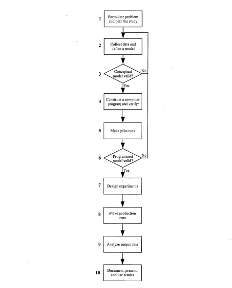
2.3.1 Law and Kelton Law and Kelton (2000) proposed a ten step approach to model building (see Fig. 2.1 on page 9).
1 Problem formulation and planning of the study. This step includes discussion, of the objectives, the specific questions to be answered by it, the components to be modelled, the time frame, performance measures, the software to be used and the overall scope of the model.
2.3 General principles
should include the goals of the study, the performance measures, detailed descrip tions of the system and its subsystems in bulleted form, what was simplified and why, summaries of data and sources of information.
3 Validity of the conceptual model? This is an important step to assure the model’s assumptions are complete and correct.
4 Programming and program verification. Once the conceptual model’s validity is established, the model is translated into computer code, either through a program ming language (e.g. Fortran or C), or through simulation software (e.g. Arena™ or AutoMod™) and debugged.
5 Pilot runs. At this phase, pilot runs are made to establish its validity in the next step. 6 Validity of programmed model? Here, the pilot runs are used to compare the model
to the system if possible. More generally, the program should be reviewed for correctness and to determine the model factors which have most influence on the performance measures.
7 Design of experiments. Here, the appropriate number of independent simulation runs, length of runs and warm-up periods for each configuration of interest are established.
8 Production runs. At this step, the experiments defined in the previous phase are run 9 Output data analysis. The data obtained from the production runs is analysed to
compare alternative systems or systems configurations and their overall perfor mance.
2.3 General principles
No Conceptual model valid?
Yes
No Programmed model valid?.
[Yes Formulate problem
and plan the study
Construct a computer progrart) and verify* Collect data and
define a model
Make pilot runs
Make production runs
Analyze output data
[image:24.612.59.534.72.662.2]Document, present, and use results Design experiments
2.3 General principles
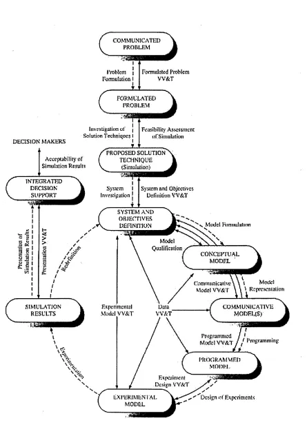
2.3.2 Balci Balci (1990) defined the simulation life cycle as consisting of 10 phases, and as a reiterative process. In order to attempt an answer to this question, the life cycle of a simulation study needs to be analysed step by step, looking at the consequences of a change at any stage for the other processes in the life cycle. This analysis is based on the life cycle of a simulation study by Balci (1990), depicted in Fig. 2.2 on page 12.
1 The first process, problem formulation, links a communicated problem to a for mulated problem and is the first process involving an analyst. This is the stage at which the problem gets defined to the point where “specific research action” can be taken (Balci 1990).
2 The investigation of solution techniques constitutes the second process. Depend ing on the outcome from the first phase, simulation or another analysis tool is cho sen.
3 The system investigation is the next process and deals with defining the objectives of the simulation model and serves as the basis for building a conceptual model. 4 The next phase in the life cycle is model formulation, where conceptual models
of the system under study are built, based on the objectives outlined in the system investigation. At this stage the decision about the underlying data is also made, i.e. whether to use a probabilistic or deterministic model. This phase also consists of building the input data, for example through sampling of actual data to extrapolate the distribution to then feed the data into the model.
5 During the model representation phase, the conceptual model created is adapted for different audiences, such as experts, nontechnical people etc, who all need different representations, e.g. pseudo code, flowcharts or structured graphs. 6 Programming. Once the model representation has been achieved, the programmer
turns his representation into computer code and debugs it, thus constructing the simulation model to be run. With modem simulators, e.g. Arena™, the program ming stage has been greatly simplified, as graphical modules are used, and no line by line programming is, over all, necessary. This makes both the programming and the debugging much faster.
7 Once the simulation model is fully programmed, and therefore executable, the next stage is the design of experiments, i.e. to decide on the best combination of para meters to achieve the desired results.
2.3 General principles
9 At the redefinition stage, the existing model is changed, to adapt it to the current situation, and to provide for new experiments. Balci differentiates between five different reasons for possible changes to the model: (1) updating the model to the current, i.e. new, stage of the actual system, (2) altering it to obtain another set of results (3) change it for maintenance, (4) adapt it for another use and (5) redefining a new system for studying alternatives.
10 Presentation o f simulation results. Parallel to redefining the model, the simula tion results are interpreted and presented
2.3 General principles
COMMUNICATED PROBLEM
J 1
Problem j Formulated Problem Formulation 1| VV&T
1 4 T *
DECISION MAKERS
FORMICATED PROBLEM
Investigation erf
Solution Techniques 1
I
Fcasib Buy Asses sms nc
o f Simulation
PROPOSED SOLUTION
TECHNIQUE
(Simulation; \cceptabjltty of
Simulation Results
INTEGkATED
DECISION
SUPPORT System and ObjectivesDefinition VV&T
System Investigation j
SYSTEM a n d
OBJECTIVES
DEFINITION •vModel Formulation
NV
1
Model Qualification
a K
CONCEPTUAL MODEL
l Mwlcl \ Rcpresemaliun Communicative
Model W & T
SIMULATION
RESULTS Model VV&TExpert mental W A TData COMMUNICATIVEMODELS)
Programmed / } ,
PROGRAMMED
MODEL Experiment
Design VV&T
EXPERIMENTAL
MODEL
[image:27.612.94.539.44.664.2]Design of Experiments
2.3 General principles
2.3.3 Banks and Carson Banks and Carson (1984) showed a slightly different simu lation modelling process. In this 12-step flowchart, (see Fig. 2.3 on the next page), the verification and validation stages are firmly engrained in the process.
1 Problem Formulation. At this stage, a problem with an existing system or one under design is stated. On some occasions, there might be a need to reformulate the problem at a later stage.
2 Setting of objectives and overall project plan. Here, the modeller establishes which tool should be used (e.g. simulation or another analytical tool) as well as a set of assumptions. Also, the goals and definition of the project are defined, along with methods to evaluate the effectiveness of alternatives.
3 Model Building. This refers to devising a conceptual model of the system un der study. This means a more or less simplified, abstracted representation of the processes to be studied consisting of the essential components only.
4 Data Collection. Data about the system is gathered if possible. If no data is avail able, rules of thumb or personal experience are used to approximate distributions. Data requirements may change as the model and its complexity progresses.
5 Coding. Once the conceptual model is established and the data gathered, the con ceptual model is translated into executable code, i.e. into the actual simulation program.
6 Verification. This stage is necessary to assure the coded model does not contain any bugs and performs as expected and intended. If this verification fails, the code needs to be reviewed and corrected until it passes verification.
7 Validation. Here, the focus is on verifying whether the model represents the sys tem to be modelled with sufficient accuracy. If the model does not represent the behaviour of the real system with sufficient accuracy, the conceptual model and/or the data gathered needs to be reviewed.
8 Experimental design. This involves designed the alternatives to be studied, along with the number of replications, the replication length and warm-up periods.
9 Production runs and analysis. This phase consists of running the experiments . designed in the previous step and analysing the results thus obtained.
10 More runs? At this stage, the modeller has to verify whether the results obtained thus far are sufficient, or whether more runs or different experiments have to be run. 11 Document study and report results. The results obtained from the simulation
2.3 General principles
yes yes
More Runs?
no Document Study \ report results
no Verified?
yes
no
no Validated t
yes
Coding
Collection Data Model
Building
Experimental Design Problem
Formulation
Production Runs & Analysis
Implementation Setting of Objectives and
overall project plan
Figure 2.3: Steps in a simulation study (Banks and Carson 1984)
important if the simulation is to be reused and/or modified, especially if that will be done by another analyst
12 Implementation. Depending on how well the previous steps have been conducted, the implementation of the results from the experiments will be more or less suc cessful.
In addition to these 12 steps, Banks and Carson also broke their simulation study into 4 phases (see also Fig 2.4 on the following page):
2.3 General principles
Problem Formulation
Setting of Objective and Overall Design
6. Verification 3. Model Building
4. Data Collection 7. Validation 5. Coding
8. Experimental Design
9. Production Runs and Analysis 10. Additional Runs
11. Document Program and Report Results
12. Implementation
Runtime
Implementation
Discovery
Model building
and
data collection
Figure 2.4: Phase structure (Banks and Carson 1984)
2 Modelling. This phase consists of steps 3 through 7 and needs constant involvement of the problem owner.
3 Running the model. Here, steps 8 through 10 are at work, delivering statistically sound results.
4 Implementation. This phase involves steps 11 and 12.
2.3.4 Kelton, Sadowski and Sadowski Kelton et al. (2002) proposed an 11-step ap proach:
1 Problem formulation. This consists of finding and formulating the problem and getting an understanding of the system under study.
2 Setting of objectives. Here, clear objectives for the study and its goals are estab lished
2.3 General principles
4 Code the model. This refers to the translation of the conceptual model into com puter code
5 Model verification. Once the model is coded, logic of the model should be assessed with the problem owners and the model should also be verified as to whether “the right things happen with 'obvious' input” Kelton et al. (2002).
6 Model validation. Here, the focus is on verifying that the simulation do model the real system.
7 Design of experiments. Once the model is verified and validated, the next step is to plan the experiments to be run to get the right answers to the right questions. 8 Run the experiments. At this point, the experiments designed in the previous step
are carried out to obtain results for later analysis.
9 Results analysis. Here, the results obtained from the experiments are analysed sta tistically.
10 Get insight. This means making sense of the analysed results, finding the implica tions of the results so they can be used for decision making.
11 Documentation. All the steps listed above should be documented, including the goals and aims of the simulation as well as the insight gained from analysing the results. This is important if the model is turned over to the problem owner for future use by someone else.
2.3.5 Benjamin et al. In their paper, Benjamin et al. (2000) proposed another concept, consisting of only three levels, as depicted in Fig 2.5.
Domain
Level
Design
Level
Analysis
Level
Ontology Descriptions Process Descriptions
>Input Specifications ’ Simulation Specifications ' Experiment Specifications 'Optimization Specifications
• Input Data Analysis • Simulation Execution • Experiment Analysis • Optimization Analysis Domain
Analysis
Model Specification
Execution & Analysis
2.3 General principles
At the domain level, information about the system and the problem to be studied are gathered. Benjamin et al. (2000) referred to this also as “domain analysis
At the design level, where “model specification” takes place, the objective and goals of the simulation project are defined, the model conceptualised and performance measures established.
The design of experiments, running them and analysing the results take place at the
“execution and analysis level”.
Furthermore, they created this approach specifically with the aim of enabling or sim plifying reuse.
2.3.6 Other approaches Robinson (1994) suggested a four-stage process, stating that:
“Despite the fact that these have been shown in a linearfashion, moving from problem definition to model building and so on, the additional arrows aim to
demonstrate the iterative nature o f the process.”
This process is depicted in figure 2.6
Problem definition
Model building and testing
Experimentation
Project com pletion and implementation
Figure 2.6: Simulation project's: an overview (Robinson 1994)
2.3 General principles
Tye (1999) developed a methodology where verification and validation are done con currently, together with the specification and design & development stages.
Robertson and Perera (2001) addressed the problems with data collection in great de tail, looking at the issues of:
• data accuracy
• types of data sources • data systems
• data duplication • timeliness
They then went on to suggest four data input methodologies offering increasing au tomation for the read/write processes that link the simulation to the input data.
The first methodology is based on the input data being directly input to the simulation model by the model builder. In the second methodology, the input data is read out from a intermediary computer application, such as a spreadsheet or database which needs to be manually populated by the model builder/project team. Their third methodology consists of an intermediary software that automatically reads and writes the relevant data to and from the corporate business system, e.g. ERP (Enterprise Resource Planning) systems. The fourth methodology put forward by Robertson and Perera consists of an automated read and write solution that directly links the simulation model to the corporate business system, thus eliminating the intermediary computer applications.
However, they also pointed out that the latter two methodologies, although in principle reducing the complexity of data collection, also carried certain problems. Among them is the difficulty to create an interface for the ERP system that provides the right data in the right amount. Another is the fact that there is no industry standard for ERP.
De Vreede et al. (2003) described a modelling method in which they differentiated be tween the conceptual model, which describes "the structure o f the organizational processes and their coordination ”, and the empirical model, which contains more detail than the conceptual model it is derived from. Their conceptual model contains the aspects of net work model showing the communications and interactions between the process nodes, the process model showing the sequence of activities in a process and the actor model
2.4 Types of adaptability in Simulation Models
2.3.7 Comparison of approaches All of the above approaches to simulation mod elling consist of 10 to twelve steps, which can also be grouped into a few phases, as Banks and Carson (1984) and Benjamin et al. (2000) showed. Another important point that threads through all those approaches is iteration. Though this principle is most obvi ous when it comes to verification and validation of a model, it also has to be noted that a change at every single stage is possible. As Banks and Carson (1984) explicitly stated,
“there are occasions where the problem must be reformulated as the study progresses “there is constant interplay between the construction o f the model and the collection o f the needed input data “as the complexity o f the model changes, the required data ele ments may also change
The above statements are important as they show that change can happen in any phase, at any stage in the modelling process. Thus, this forms the basis for investigating which changes are most difficult to implement or most frequent.
The data collection issue treated by Robertson and Perera (2001) does not constitute an approach in itself, but points to another important element that can aid in making simulation modelling more adaptable, and changes easier to implement.
For the remainder of the work, the steps in a simulation study proposed by
Law and Kelton (2000) was chosen, as this approach offered the best starting point for including the steps necessary to make simulation models more adaptable.
2.4 Types of adaptability in Simulation Models
“Flexibility is the ability to respond effectively to changing circumstances.”
Mandelbaum (1978)
Adapt: “1) fit, adjust, make suitable 2) alter or modify to fit for a new use, new conditions 3) undergo modification to fit a new use, new conditions”
The New Shorter Oxford English Dictionary.
Before looking at the different approaches devised to improve the adaptability of sim ulation tools, a quick overview of different definitions in the area of flexibility/adaptability is considered useful.
2.4 Types of adaptability in Simulation Models
and machine flexibility.
By action flexibility, Herrmann et al. referred to planning, e.g. a new plant, without knowing the future. Mandelbaum (1978) defined this type of flexibility as “the capacity for taking new action to meet new circumstances ” and state flexibility as “the capacity to continue functioning effectively despite change This refers to the ability to automatically adapt to changes, while the former requires manual intervention.
Buzacott (1982) defined job flexibility as “the ability o f the system to cope with changes in the jobs to be processed by the system ” and machine flexibility as “the ability o f the system to cope with changes/disturbances at machines/workstations Both refer to the ability to process a variety of jobs, with job flexibility being focused on the system as a whole, while machine flexibility refers to the individual machine.
Slack (1983) suggested the following types of flexibility which apply to a complete manufacturing system:
• New product flexibility: ability to introduce a new product
• Product mix flexibility: ability to produce a certain combination of products
• Quality flexibility: ability to change the “quality level o f one or more o f its prod ucts” (Slack, 1983)
• Volume flexibility: ability to vary the aggregate output of a production system
• Delivery flexibility: ability to vary its delivery time, i.e. its production time
Slack (1991) also introduced two dimensions of flexibility: Range flexibility and re sponse flexibility. Range flexibility looks at the range of possibilities in terms of product, mix, volume and delivery flexibility. It constitutes the time-independent capacity for adap tation. Response flexibility looks at the time necessary to bring about the modifications necessary as laid out in the range flexibility.
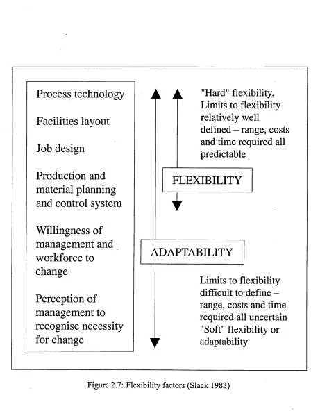
Furthermore, Slack (1983) differentiated between different levels of flexibility. He uses the term “flexibility” when talking about well defined limits, enabling it to be mea sured and “adaptability” when the overall flexibility is not readily measurable, (see Fig. 2.7 on the next page)
Gerwin and Kolodny (1992) proposed six different types of flexibility:
• Mix flexibility: this looks at the ability to vary product combinations; this is equiv alent to Slack’s (1983) product mix flexibility
2.4 Types of adaptability in Simulation Models
A A
"Hard” flexibility.
Limits to flexibility
relatively well
defined - range, costs
and time required all
predictable
FLEXIBILITY
*
ADAPTABILITY
Limits to flexibility
difficult to define
-range, costs and time
required all uncertain
"Soft" flexibility or
[image:36.612.75.523.58.660.2]y
adaptability
Figure 2.7: Flexibility factors (Slack 1983)
Process technology
Facilities layout
Job design
Production and
material planning
and control system
Willingness of
management and
workforce to
change
' 2.4 Types of adaptability in Simulation Models
• Modification flexibility: ability to customize product attributes on an ad hoc basis • Volume flexibility: enables changes to the aggregate output; this is equivalent to
Slack’s (1983) definition of volume flexibility
• Rerouting flexibility: “the ability to adjust the sequence o f machines through which a part flow s” (Gerwin and Kolodny, 1992). This deals with long- and short term downtime aspects
• Material flexibility: ability to deal with variations in composition of materials and in dimensions
In their classification, mix, changeover, modification and volume flexibility are market oriented. This is because the demand for products is the relevant uncertainty. Re-routing and material flexibility are process operations oriented, as the relevant uncertainties reside within the manufacturing technology and/or its inputs.
Weihua and Baofeng (1999) identified four different classifications of flexibility: hor izontal, vertical, temporal and by object of variation. They point out that in addition to these four classifications, there are also combinations of these logics, of which the most common appears to be that of temporal and object o f variation.
The horizontal classification, or ‘classification by phases’, looks at the value chain. That is, it looks at the flexibility of the various stages of the manufacturing process on the one hand, and at the upstream and downstream phases (i.e. purchasing and distribution flexibility). They also use the terms internal and external flexibility, respectively.
The vertical or ‘hierarchical’ classification looks at the level of detail, e.g. the flexi bility of individual resources or of the whole system. Gerwin (1987) also defined levels of flexibility to help with the classification of flexibility:
1 individual machine or manufacturing system 2 manufacturing function (e.g. cutting or assembling)
3 manufacturing process for a product or group of similar products 4 the factory
5 a company’s factory system
The temporal classification is concerned with the short, medium and long-term flex ibility, while the classification by object of variation looks at machine, product, process, operation, routing, volume, expansion and production flexibilities.
2.5 Adaptability of Simulation Tools
of the uncertainty connected to the future, the “value offlexibility is difficult, if not im possible, to ascertain”. Similarly to Jones and Ostroy (1984), who state that flexibility
increases with the size of sets of future positions at various cost levels, she mentions that
“flexibility is associated with the initial state but measured by the number o f states it can move to or the number o f choices available in the second stage More generally, this refers to the definitional elements of flexibility, which she suggests as:
• range: the ability to adopt different states (Slack 1983) • time
• change
• conditions of uncertainty: the importance or cost of uncertainty • favourability: “the value or benefits o f change ” (Ku 1995)
2.5 Adaptability of Simulation Tools
The need for adaptability, i.e. the need to implement change, has been recognized as noted in the previous section. In order to provide for adaptability in simulation models, different approaches have been devised, of which some are described here.
2.5.1 Data-driven simulators Pidd (1992) looked at data-driven simulators in closer
detail, suggesting as its main features: • “Pre-Programmed simulation ‘model’
• ‘Model ’ suited to range o f applications
• No programming by the user
• User provides data to simulator
• Data numerical, logical or textual”
Pidd (1992) defined data-driven simulators as follows:
“The idea o f a data-driven simulator is that the user should be unaware o f the code o f the underlying simulation program other than that which is hinted at by its user interface.”
2.5 Adaptability of Simulation Tools
geared towards a narrower application, citing flexible manufacturing systems as one such example.
Pidd (1992) further explains the main elements of such a data-driven simulator, con sisting of:
• simulation logic: the computer based representation/translation of the conceptual model
• libraries:
- general library containing general routines such as scheduling events - sampling routines, which handle distribution generation
- graphic library for animation and display
• model configurator: the ‘interface’ through which the user can input the data, whether through text or GUI
• filer, which handles the storage of (output) data
• experimental frame, in which general run parameters (e.g. replication length or number of replications) are set
• report generator, which outputs the data obtained during the simulation runs for easier analysis
2.5.2 Programming versus assembling Simulation models can be created through the use of general-purpose programming languages, e.g. FORTRAN or C/C++, special purpose simulation languages, e.g. GPSS, SIMSCRIPT, SIMAN, or high-level simula tion packages such as Arena™ or Witness™ (Law and Kelton 2000, Kelton et al. 2002). As Law and Kelton (2000) pointed out, general purpose languages, such as FORTRAN, are “highly customisable and flexible, but also painfully tedious and error-prone since models [have] to be coded pretty much from scratch every time”. Pidd (1992) referred to packages like Witness, where the code remains hidden, as data driven generic simulators. Special purpose simulation languages, which came later, are specifically geared towards the building of simulation models, thus simplifying some tasks. They tend to include random-variate generators and built-in statistics gathering routines (Banks and Carson 1984). Application-oriented simulation packages facilitate model-building by providing a graphical user interface (GUI) and 2- or 3-dimensional animation capabilities.
2.5 Adaptability of Simulation Tools
already contain some helpful constructs. However, the model builder still needs very good knowledge of the program and programming skills with it. Simulation packages, on the other hand, offer the greatest ease in terms of model building, as the builder does generally not need to have any knowledge of the underlying code, as the constructs are represented by icons which only need to be pulled onto the modelling area.
While the ease of building simulation models increases with the use of application- oriented simulation packages, their functionality is somewhat limited. This is due to them being geared towards rather more specific application areas. As Kelton et al. (2002) noted:
“a simulation package that relies on a fixed number o f modelling constructs with no capability to do some kind o f programming in any manner is bound to be inadequate for certain systems encountered in practice” Thus, in order to increase the functionality of such simulators, the model builder can access a lower level, i.e. the code itself to modify it. Also, these simulation packages are increasingly integrated with other software. Arena™, for example, offers extensions to integrate other programs such as Microsoft (MS) Excel and Visual Basic, as well as providing the option of using external code in the form of the C programming language.
Although the functionality of simulators can be increased this way, it necessitates yet again programming skills by the simulation modeller.
2.5.3 Programming differences Another differentiation in terms of simulation soft ware distinguishes between object-oriented and component-based programming.
Joines and Roberts (1998) described simulation programs as procedural when a prob lem is subdivided into procedures which are either represented by components such as queues or by means of programming code with data structures. Examples for such pro cedural approaches are GPSS (General Purpose Simulation System), SLAM (Simulation Language for Alternative Modelling, the basis for AweSim) and SIMAN (SIMulation ANalysis, the basis for Arena™)
They warned of the following problems with this procedural approach:
• Procedures only correspond to methods and algorithms, not to real world compo nents. This means that a context must be given for the procedures, such as queuing situations.
2.5 Adaptability of Simulation Tools
• The only way to modify such simulations is through user code, compiled in a gen eral programming language. The communication between the user code and the simulation vendor’s code is through function calls, ie where the externally pro grammed routine or program is called and started from within the simulation code. Here, the problem is that this leaves the simulation code itself quite vulnerable to mistakes made by the user.
Object-oriented programs, on the other hand, involve the notion of encapsulation. This means that the properties of the object are included within the object itself, instead of being spread, e.g. throughout a program. This means that implementing changes to the object is quite forward. Also, objects are created in the form of object classes, which define certain general attributes, ie some sort of ‘template’, which can then be used as ‘instances’, ie copies, of this object class. Each of these copies would have the same prop erties as its class, but allow certain values of it to be changed. Another important aspect of object-oriented programming is inheritance, meaning that the properties of an object can be reused in another object, including additional attributes. For this reason, Callan (1994) pointed out that object-oriented programming has a great potential for reusing components. Moreover, he talked about “an expectation that object-orientation will de liver increased productivity through the definition o f reusable components and will also deliver easier to maintain systems” (Callan 1994).
Also, designers of objects or object classes can determine which properties should be visible to the user and which should not. In procedural style, the programmer must decide whether to make the whole code available to the end user or none at all.
Joines and Roberts (1998) mentioned that programs such as Arena™ and AweSim of fer extended possibilities, called object-based features, where new objects can be created out of existing objects. However, apart from objects through composition, these programs do not offer any more possibilities. This means that new objects, which are completely independent from existing basic building blocks, cannot be built.
2.5 Adaptability of Simulation Tools
is to improve the interoperability and accessibility of MS&V for US industry.
This architecture consists of a conceptual model of a generic job shop specified in the Unified Modelling Language (UML). They chose UML as this “is a recognized standard for structured and object-oriented modelling” (McLean et al. 2002). UML is a visual language, in which boxes and lines are used to depict constructs. Diagrams were then created for use cases, static data structures, sequences and states/activities. Within the use case diagrams, various generic forms were built to represent the various activities and actors that can occur. The UML models are then translated into Extensible Markup Lan guage (XML). The XML files are of textual format, i.e. they do not need being compiled into binary computer code. As a result, XML files can be read by humans and can be easily implemented in off-the-shelf software applications without the need for special, additional programs.
Apart from the UML/XML structure, the architecture proposed by McLean et al. (2002), McLean and Leong (2002), Lee et al. (2003) consists of a machine shop emulator and a discrete event simulator, which are linked, and a user interface. The emulator manages the sequencing of orders, tasks and jobs, while the discrete event processor manages the flow of entities through the generic event queues and the state changes. The graphical user interface (GUI) provides for the data entry to the system. The main idea behind this approach is the linking of “machine shop software applications with simulation ” via standard interfaces (Lee et al. 2003). The provision of such a standard interface would in turn drastically reduce the time - and costs - associated with the construction of the simulation model and the data exchange.
Their machine shop emulator contains more data than necessary to run a simulation; in fact, McLean et al. (2002) stated that “the shop data model currently encompasses a significant portion o f the data required to actually run a real machine shop The idea behind this was to eliminate the abstraction phase, where data from the actual system is simplified for the creation of the simulation model.
Their machine shop emulator was implemented in Visual Basic™ (Microsoft™) and SIMAN simulation language (Rockwell Software), the GUI was created in Visual Basic alone, while Arena™ (Rockwell Software) is used as the discrete event simulator.
2.5 Adaptability of Simulation Tools
an ISO standard to describe language-neutral information models and EXPRESS-G, a graphics-based version of EXPRESS. Based on those models, a Microsoft Access data base was created, containing all the components from the EXPRESS models and the relationships between them. The actual simulation model was then built through the use of a model builder, which they created for Arena™ and ProModel™. Their model builder gathered the necessary information from the Microsoft Access™ database. This approach is based on the NIST initiative of libraries for formal, neutral models of simu lation components. Son et al. (2003) stated that “Each o f these components would have views tailored to specific modeling scenarios ... defined by different modeling templates
- such as an equipment simulation, a material flow simulation, a supply chain simulation and so forth ”. Furthermore, they have oriented their development towards internet-based simulation.
2.5.5 Adaptable simulation models Gahagan and Herrmann (2001) noted that simu
lation models are not used to their full capacity “due to the cost o f maintaining an accu rate simulation model”. They defined this maintenance cost as the “man-hours necessary to update a simulation model”.
They next proposed to ways to reduce this maintenance cost:
• reducing the maintenance cost by making the model more adaptable
• eliminating the maintenance cost by automating it, thus eliminating the need for respective man-hours
More generally, McLean and Leong (2001) suggested that cost can affect the very basic decision of whether to use simulation at all. Some of the factors they consider of prime importance in that respect are:
• The company’s resources
- availability of discretionary funds
- simulation skills and experience base of current staff or consultants
- existing information systems infrastructure (availability of required computer systems, related software applications, and data bases)
• scope and complexity of the target simulation application area
• availability of turnkey or readily-adaptable simulation models and solutions • availability and format of input data
2.5 Adaptability of Simulation Tools
- salaries
- training classes, learning curves and maintenance - translation of existing data
- systems integration with other software applications
The approach by Gahagan and Herrmann (2001) looked at adaptability of simulation models from the point of view of a production control framework, more precisely in the form of push/pull categories. In their framework, queues, workstations and the shop interact with each other and the outside world via controllers. Those queue, workstation and shop controllers then operate based on 4 component types and their attributes. In their approach, components can be physical elements as well as information, and are grouped into four types, which are further specified by attributes, such as queue entry time, the destination workstation etc. The 4 basic component types are categorized as follows:
• Type 1, Material components
• Type 2, Product permission components • Type 3, Resource permission components • Type 4, Batch components
This framework was implemented as an Arena Application Solution Template (AST) in the Arena Professional Edition.
Oscarsson and Moris (2002) also looked at adaptability of simulation models. How ever, rather than focussing on the control framework, they investigated the modification a manufacturing system goes through during its life cycle, which is much longer than that of any individual product produced in with this system. More specifically, they state that
“/ djuring its life the manufacturing system will go through a number o f changes
As reasons for such changes to the manufacturing system they state: • Introduction o f a new product
• Rationalisation o f the product
• Changed legal provisions
2.5 Adaptability of Simulation Tools
One way to improve understanding of such models, according to Oscarsson and Moris (2002), is to use standardized notations for the documentation, such as Unified Modelling Language (UML), Integrated DEFinition language 0 (IDEF 0) and Jackson Structured Programming (JSP).
They identified 6 criteria that need to be satisfied in order to obtain a good documen tation:
• Neutral notation: not limited to specific languages, systems or software, but able to support a variety of simulation packages.
• Generic notation: to describe a variety of systems of different purpose, complexity and scope
• A recognised notation: to improve communication and prevent misunderstandings and interpretation difficulties
• User friendly notation: to help readers overcome issues relating to the difference between natural language and abstract code
• Descriptive in several levels: to allow different types of users to gain access to a description suitable to their needs, e.g. bottom-level for the modeller/programmer, higher level for a model user
• In-house competence: use of documentation standards the company is familiar with (e.g. IDEFO or UML)
2.5.6 Other approaches Another approach to make simulation models more adapt able is the High Level Architecture (HLA). This approach, which is widely used in mil itary simulation applications, was created in order to combine existing simulations into one. As various simulations are built on different packages, or written in different lan guages, the problem of incompatibility had to be overcome. In the case of HLA, this was done through ‘wrapping’ the existing application into a single virtual object, a ‘federate’. This encapsulating is done through an Object Model Template (OMT). The combination of federates into a larger simulation is called ‘federation’ (Davis and Moeller 1999).
Yilmaz and Oren (2004) stated that “a model is reusable to the extent its original as sumptions are consistent with the relative constraints o f the new simulation study”. They
2.5 Adaptability of Simulation Tools
components.
Spiegel et al. (2005) were concerned with the reusability in itself, proving that it is very challenging to gather all assumptions and constraints. They then suggested that for models to be composable and reusable, “comprehensive identification o f constraints” would be necessary, and that methods for identifying critical constraints need to be devel oped.
Zhao and Verbraeck (2005) proposed a framework that allows multiple users with dif fering needs in terms of modelling detail to make use of a hierarchical simulation system. Their framework aims at supplying users at various hierarchical levels within a company with a web-based simulation tool that works at different levels of model detail, depending on the user’s needs.
Garlan et al. (1995) previously proved the issue of incompatibilities, and lack of knowl edge of assumptions and pointed out four aspects that need to be satisfied to achieve long-term compatibility and reusability:
1 Explicitness o f assumptions, ie the need to explicitly document all assumptions, so as to make it easier to detect mismatches.
2 Use o f orthogonal sub-components for constructing large pieces o f software; build subsystems that can work independently of their higher-level system.
3 Provision o f techniques for bridging mismatches, ie provision of tools to aid with wrapping components and data translation to overcome those problems.
4 Development o f design guidelines, ie of generally applicable rules for the develop ment of components to simplify their reuse.
2.5.7 Discussion of adaptability approaches As has been argued in § 2.5.2, program ming languages are highly customizable and adaptable, but they need the most profound programming knowledge to be used to their full extent. At the other side of the spectrum, the commercial off-the-shelf (COTS) simulation packages greatly reduce the necessity of programming knowledge, but simultaneously limit their adaptability.
2.5 Adaptability of Simulation Tools
is still procedural and will probably remain so in the near to mid-term future because of the reluctance of companies to retrain their staff on a new system and recreate existing simulations in the new package.
The object-based features mentioned by Joines and Roberts (1998) extend the use of procedural software, but still requires programming knowledge and does not offer the same programming adaptability as o-o programming does.
Overall, the approaches taken by McLean et al. (2002) and Son et al. (2003) aimed at simplifying the generation of simulation models, enabling the reuse of existing ones and the construction of complex models from simpler ones. Son’s approach further aims at improving internet-based simulation facilities. Hence, this approach constitutes a novel way to improve and increase the use of simulation in the manufacturing domain.
The concept of interoperability in simulation is not new (Banks 1997; 2000, Pidd et al. 1999). However, apart from first tentatives in research, there is no sign of a wider-spread introduction of such standard data formats. More importantly, the idea