Enabling Centralized Access to a Reactive Architecture
for Hardware Control Systems
Rob Stortelder
University of Twente
P.O. Box 217, 7500AE Enschede
The Netherlands
rob@stortelder.eu
September 3, 2019
Graduation committee
First supervisor Dr. A. Fehnker University of Twente
Second supervisor Dr. L. Ferreira Pires University of Twente
First external supervisor ing. P. Noltes
Thales Netherlands B.V.
Second external supervisor M. Horsthuis MSc Thales Netherlands B.V.
c
Abstract
This study describes the process of introducing an API gateway with cross-cutting features into a reactive architecture. The aim of this implementation is to introduce these cross-cutting features into the architecture without changing the services of the reactive architecture. Ex-amples of cross-cutting features are: security, tracing, monitoring and request composition. The target design required the translation of an asynchronous protocol to a synchronous pro-tocol. This was achieved by identifying conversations based on sequence diagrams of current communications in the architecture of Thales.
Contents
1 Introduction 5
1.1 Motivation . . . 5
1.1.1 Responsiveness . . . 6
1.1.2 Resilience . . . 6
1.1.3 Elasticity . . . 6
1.1.4 Message-driven . . . 7
1.2 Objectives . . . 7
1.3 Approach . . . 8
1.4 Report Structure . . . 8
2 Background 10 2.1 API Gateway Usage . . . 10
2.1.1 Netflix . . . 10
2.1.2 Lyft . . . 11
2.2 API Gateway Market Analysis . . . 11
2.2.1 Protocol Support . . . 12
2.2.2 Functionalities . . . 14
2.3 Synchronous and Asynchronous Communication . . . 15
2.4 Concluding remarks . . . 16
3 Thales System Analysis 17 3.1 Thales Architecture . . . 17
3.2 Current Challenges . . . 17
3.3 Sequence Diagrams . . . 19
3.3.1 Request Current State . . . 20
3.3.2 Request Composition . . . 20
3.3.3 Power on Subsystem . . . 21
3.3.4 Periodic Task . . . 22
3.3.5 Spontaneous State Change . . . 23
3.4 Concluding remarks . . . 24
4 Protocol Translations 25 4.1 Conversation Types . . . 25
4.1.1 Request/Response . . . 25
4.1.2 Request with fixed amount of Responses . . . 26
4.1.3 Request with Stream of Responses . . . 26
4.1.4 Server Push . . . 26
4.2 Push Technologies . . . 27
4.2.1 Requesting changes . . . 27
4.2.2 Continuous open connections . . . 27
4.2.3 Client-as-a-server . . . 27
4.2.4 Applying to hardware control system . . . 28
4.3 Translations . . . 28
4.3.1 Request/Response . . . 29
4.3.2 Server Push . . . 29
4.3.4 Request with Stream of Responses . . . 31
4.4 Other Hardware Control Systems . . . 32
4.5 Concluding Remarks . . . 32
5 Implementation 34 5.1 Target architecture . . . 34
5.2 API translator component . . . 34
5.2.1 API Descriptions and Code Generation . . . 35
5.2.2 Integrating Generated Server Code . . . 35
5.2.3 Request/Response Implementation . . . 36
5.2.4 Server push Implementation . . . 36
5.2.5 Request with Multiple Responses Implementation . . . 37
5.2.6 Request with Stream Responses Implementation . . . 38
5.3 API Gateway . . . 39
5.3.1 Installation . . . 40
5.3.2 Configuration . . . 40
5.3.3 Security . . . 41
5.3.4 Monitoring/Logging/Tracing . . . 42
5.3.5 Request/Response Transformation . . . 42
5.3.6 Request Composition . . . 43
5.4 Concluding remarks . . . 43
6 Results 44 6.1 Solutions to Challenges . . . 44
6.2 Performance . . . 46
6.3 Discussion . . . 47
7 Final remarks 49 7.1 Conclusions . . . 49
7.1.1 Protocol Translations . . . 49
7.1.2 Cross-cutting Features . . . 50
7.1.3 Implementation . . . 50
7.1.4 General conclusions . . . 51
7.2 Future Work . . . 52
7.2.1 Apply Directly to Thales API . . . 52
7.2.2 Analysis with Customer Implementation . . . 52
7.2.3 Experiment with http/2 . . . 52
7.2.4 Test more API gateways . . . 52
7.2.5 Performance Optimization . . . 52
7.2.6 Validate Solution with Other Hardware Control Systems . . . 53
8 Appendix 54
A OpenAPI Definition Example 54
B Docker Compose File 55
1
Introduction
This chapter presents the motivation, objectives, approach and structure of this thesis. Section 1.1 describes the motivation for this research. Section 1.2 presents the general objectives. Section 1.3 contains the approach that was followed to achieve the objectives. Section 1.4 presents the further structure of this thesis.
1.1
Motivation
There is a trend of moving toward distributed architectures as an alternative to monolithic architectures. These distributed architectures introduce a separation of concerns by dividing the business logic across services. Reactive systems can be designed as distributed systems, which are based on a set of architectural design principles. These principles state that a reactive system should be responsive, resilient, elastic and message-driven [8]. Such systems are capable of responding quickly and consistently, stay responsive in the face of failure, adapt to varying changes in input rate and rely on asynchronous message passing.
This study is aimed at a variant of reactive architectures which is focused on control systems for specialized hardware (e.g., radar systems). The architecture should still be responsive, resilient and is message-driven, but the interpretation of elasticity is slightly different. The architecture should still be able to react to a varying amount of load, but there is a fixed hardware limit to scaling possibilities. This is because hardware systems have a fixed amount of computing power available, so that the fixed amount of available resources should be allocated as effectively as possible. Hardware systems mainly receive control commands from a couple of users, so they do not have to handle millions of requests from users. These request can still require a high amount of computing power. An example is in case a high amount of sensor-data needs to be processed.
Customers of hardware control systems preferably have a centralized entry point for uniform communication with the hardware system. To achieve this, an API gateway can be implemented that offers a single entry point to the architecture. Figure 1 shows an example of a reactive architecture with an API gateway that facilitates access to this architecture. There are several identifiable elements in this architecture:
• Client: External system communicating with the reactive system. The client accesses the reactive architecture through the API gateway.
• API gateway: Entry point to the reactive system. This translates a single incoming API to messages for the reactive system.
• hardware control service: Service running inside the reactive system. Multiple of these services control the hardware system together. The services communicate using asynchronous message passing.
Figure 1: Reactive architecture with an API gateway
Many design choices can be made while implementing such an API gateway. The API gateway can provide different kinds of synchronous or asynchronous APIs to the clients. The gateway can also provide a wide variety of middleware features like security, logging and trace-ability. The following sections describe the different characteristics of a reactive system and how an API gateway can comply with these characteristics.
1.1.1 Responsiveness
Reactive systems should provide consistent response times to clients. In the case of hardware control systems, control commands and responses from the hardware should arrive in a timely manner. Delays can be introduced by the API gateway, as it mediates access from and to the reactive architecture. For websites, the delays for usability are in the range of a couple of hundreds milliseconds [10]. For hardware control systems, this can even be less due to the possibility of other hardware systems controlling the reactive system. The API gateway should only add a minimal delay to the total delay of the system, preferably in the order of magnitude of 10 milliseconds or less.
1.1.2 Resilience
Reactive systems should be designed to be resilient, stay functional in the face of failure. Failures should be contained in single components and not cascade beyond their boundaries. Besides the architecture being resilient, the API gateway should also be resilient, it should be able to handle failure of services. The API gateway should also be replicated to prevent having a single point of failure.
1.1.3 Elasticity
1.1.4 Message-driven
Communication between services in a reactive system is based on asynchronous message passing. Services in the reactive architecture can intercommunicate by using some kind of message passing system like a message bus. The API gateway should translate the incoming API to messages that are used inside the reactive architecture. The gateway can provide a variety of API options to clients, among these are synchronous and asynchronous APIs. An asynchronous API is more easily translatable to the reactive architecture as this architecture is based on asynchronous message passing. Providing a synchronous API requires code that is able to translate the synchronous API requests to asynchronous messages.
1.2
Objectives
In this research we worked towards solutions for common challenges when introducing an API gateway into a reactive architecture for hardware control systems. This API gateway should preserve the basic characteristics of the reactive architecture (responsive, resilient, elastic and message-driven). Several challenging areas have been identified for introducing a gateway in a reactive architecture: protocol translations, cross-cutting features and performance.
Main objective: Design and implement an API gateway into an reactive architecture for hardware control systems whilst the basic characteristics of the reactive architec-ture are preserved.
There are several challenges when implementing an API gateway in a reactive architecture. The first challenge lies in protocol translations, which are challenging due to a couple of factors. There can be a difference between the protocol requirements between the client and the gateway and the protocol from the gateway to the reactive architecture. The reactive architecture is asynchronous in nature, but a client might require a synchronous protocol, which requires the translation from an asynchronous to a synchronous protocol. Message formats from the client can be different to the formats of messages used in the reactive architecture, the gateway should transform these messages. Another element of protocol translations is request composition, where one incoming request is translated to multiple internal requests and their results are combined.
Sub-objective 1: Research methods for protocol translations from a protocol designed for a reactive architecture to a protocol suitable for use with an API gateway.
The second challenge lies in the variety of cross-cutting features that an API gateway can provide for the architecture. Examples of such features are logging, monitoring, authentication and security. The API gateway can provide such features in a centralized manner without having to change individual services significantly. This can be particularly useful when the reactive system is based on legacy technologies and is hard to change. Solving these challenges by using an API gateway can introduce delays on requests to the system. These delays should be minimized where possible, to minimize the impact on the current responsiveness of the architecture.
The third challenge is to validate the findings of this study. For this validation, an API gateway has been implemented in the sensor management system at Thales Netherlands B.V (further in this study referred to as Thales). The aim is to use an off-the-shelf open-source API gateway as an alternative to their currently implemented proprietary API gateway, which provides limited functionality. Off-the-shelf solutions are preferred as they do not require the development and maintenance effort in contrast to in-house development of an API gateway [5]. The solution should preferably be open-source in order for Thales to be able to make changes to the system if needed.
Sub-objective 3: Validate the findings by implementing and testing an API gateway prototype with protocol translations and cross-cutting features at the sensor man-agement system of Thales
1.3
Approach
Several steps have been taken to achieve the objectives described in the previous section: 1. Domain analysis The domain of API gateways has been analyzed using a literature
study. This analysis consists of two parts: an analysis of API gateway implementations by other software companies and an analysis of open-source API gateways concerning their available protocols and features.
2. Thales system analysis An analysis of the current architecture of Thales has been conducted. This analysis shows the challenges and use cases of the current API gateway implementation.
3. Analyze and implement protocol translationsA literature study into protocol trans-lations has been conducted. This study looks into translating a proprietary protocol to a protocol that is suitable for use with an existing API gateway. After this analysis the protocol translations have been implemented in the reactive architecture of Thales. 4. Select and implement API gateway An API gateway has been selected based on
results of the domain analysis and this API gateway have been included in the reactive architecture of Thales. Several cross-cutting features have been implemented using this API gateway, some examples are: security, logging and traceability.
5. Validate implementation The implementation has been validated on a variety of fac-tors. The first is the degree with which the cross-cutting features could be implemented in the API gateway without significant changes to the services. The performance impact from the implemented API gateway and cross-cutting features has been tested using a benchmarking tool. Lastly the design choices and possible alternatives have been dis-cussed disdis-cussed.
1.4
Report Structure
The further structure of this report is as follows:
• Chapter 4 discusses protocol translations from an asynchronous protocol to a synchronous protocol.
• Chapter 5 describes the approach for the new implementation of the synchronous API, with API gateway and cross-cutting features.
• Chapter 6 validates our result of the API gateway implementation.
2
Background
This section analyses API gateways and their usage in practice. Section 2.1 discusses the usage of API gateway by other companies. Section 2.2 analyses open-source API gateways in terms of their protocols and features. Section 2.3 describes synchronous and asynchronous communication characteristics. Section 2.4 contains concluding remarks for this chapter.
2.1
API Gateway Usage
API gateways are used by companies mostly to provide a single access point to a micro-services architecture. Two well known examples of API gateway usage are those of Netflix and Lyft, which are described in the next sections.These examples are picked as both companies introduce a new approach or technique for using API gateways. Netflix uses the API gateway to provide specific APIs for the different kinds of clients that run the Netflix application. Lyft re-purposes their API gateway as a sidecar service to separate the communication logic from the business logic. A sidecar service separates communication logic from business logic in services
2.1.1 Netflix
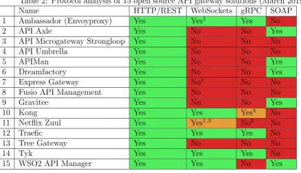
Netflix is currently one of the largest media streaming services worldwide, and provides millions of users on a daily basis with media content. Employees of Netflix regularly post entries on the Netflix techblog. This blog contains articles about technical details of the software infrastructure at Netflix. There are several entries on this blog about the API gateway implementation of Netflix [12, 25]. The Netflix app is available on a wide variety of devices, which all need to communicate with the service-oriented architecture of Netflix. Figure 2 shows how they use an API gateway to manage traffic from such devices to their services.
[image:10.595.172.420.594.741.2]The Netflix API consists of two parts: the client-facing API and the internal API to the services. The API gateway translates between these two parts. Each device communicates with the API gateway using the client-facing API. Request composition is used extensively to reduce the amount of requests from the client to the server. In Figure 2 a Playstation device is making one request to the client-facing API of the API gateway, which forwards the request to a variety of services using the internal API. The responses of these subsequent requests are combined into one response, which is sent back to the Playstation. Request composition can reduce the network overhead by combining multiple API requests into one request.
The Netflix approach moves the client-server boundary to the API gateway. Client-side developers who program the applications for different devices also develop the connector for translating the client-facing API to the internal API. This connector runs on the API gateway and is written in a server-side programming language. This means that client-side developers also should have some knowledge about server-side development. This approach reduces the dependency from the client teams on the API development teams, but requires the client-side developers to have some knowledge of server-side programming.
Netflix has open-sourced their API gateway implementation in a project called ’Netflix Zuul’ [31]. An inbound request passes through a variety of configured inbound filters, then through an endpoint filter, after which the request is forwarded to the destination. After receiving a response from the destination, the response is passed through outbound filters before it is returned to the client. Netflix Zuul offers a variety of integration options with other open-source software projects. Examples of these are integration with Eureka for service discovery (locating services in a distributed architecture) and Ribbon for load balancing (spreading request load among similar services).
2.1.2 Lyft
Lyft is a company that provides ride sharing between its users; at the time of writing they facilitate around one million rides each day. Lyft has been working to transform their monolithic architecture to a distributed architecture. This introduces challenges with service discovery, communication methods and other distributed features. The so called Envoy proxy [29] was introduced to solve these challenges in their distributed architecture. The Envoy proxy can either be used as an API gateway but also as a sidecar service, which is a service that is running besides other services and encapsulates the communication-related features such as service discovery and the use of protocol-specific and fault-tolerant communication libraries from the services themselves. Using the sidecar mechanism, service developers only write business logic in the application and communicate with the sidecar service, this forms an abstraction between business logic and communication logic [26]. Figure 3 shows examples of how Envoy is used, both as an API gateway or as a sidecar service. The ’Front Envoy’ services act as an API gateway and provides secure communications between the clients and the architecture. Each application has an Envoy sidecar that facilitates communication between services.
All the communications between components of the system pass through the Envoy proxy. This can be leveraged to implement a variety of cross-cutting features. Examples of these features are service discovery, health checking, load balancing, rate limiting, logging and tracing. Running a sidecar with each service in an architecture comes with a performance overhead. This is why the Envoy proxy is written in a low level programming language (C++), which aims to minimize the performance impact. The developers continually work on improving the performance of Envoy, they argue that the cross-cutting features and abstraction between business logic and networking are worth the (minimized) performance overhead.
2.2
API Gateway Market Analysis
Figure 3: Lyft using Envoy Proxy [30]
a list of 15 API gateways, which is shown in Table 1. This table shows the API gateways, as well as the programming language these have been written in, the release date and whether the API gateway is in active development. In the following sections, these different API gateways are analyzed by looking at the web site, documentation and source code. The first analysis focuses on the protocol support of the different API gateways, the second analysis looks into the features that are provided by the different API gateways.
Table 1: Selection of open source API gateways (March 2019)
No. Name Language Release date Active development
1 Ambassador (Envoyproxy) [1] Python March 2017 Yes
2 API Axle [2] CoffeScript December 2012 Inactive since July 2017 3 API Microgateway Strongloop [37] Javascript March 2016 Yes, but minimally
4 API Umbrella [42] Ruby October 2014 Yes
5 APIMan [3] Java September 2014 Yes
6 Dreamfactory [15] PHP October 2015 Yes
7 Express gateway [16] Javascript May 2017 Yes
8 Fusio API Management [4] PHP July 2015 Yes
9 Gravitee [21] Java October 2015 Yes
10 Kong [27] Lua March 2015 Yes
11 Netflix Zuul [31] Java May 2013 Yes
12 Traefic [13] Go September 2015 Yes
13 Tree Gateway [41] TypeScript May 2017 Yes
14 Tyk [39] Go August 2014 Yes
15 WSO2 API Manager [44] Java March 2015 Yes
2.2.1 Protocol Support
[image:12.595.59.573.451.697.2]multiple protocols, as were others are specifically build for 1 protocol. Some gateways provide partial support for some protocols, reasons for the partial support can be found in the footnotes. Descriptions of the identified protocols are as follows:
Table 2: Protocol analysis of 15 open source API gateway solutions (March 2019)
Name HTTP/REST WebSockets gRPC SOAP
1 Ambassador (Envoyproxy) Yes Yes1 Yes No
2 API Axle Yes No No Yes
3 API Microgateway Strongloop Yes No No No
4 API Umbrella Yes No No No
5 APIMan Yes No No Yes
6 Dreamfactory Yes No No Yes
7 Express Gateway Yes No2 No No
8 Fusio API Management Yes No No No
9 Gravitee Yes No No Yes
10 Kong Yes Yes Yes4 No
11 Netflix Zuul Yes Yes1,3 No2 No
12 Traefic Yes Yes Yes No
13 Tree Gateway Yes No No No
14 Tyk Yes Yes Yes No
15 WSO2 API Manager Yes Yes No Yes
1Ambassador supports WebSockets since October 2018 and Zuul since June 2018 2Mentioned on roadmap
3WebSocket connections to the gateway are supported, but not between the gateway and the services 4Basic support, only primitive passive proxy-pass is supported
• HTTP/REST [18]is supported by all major open-source API gateways and it is widely used in the open internet. HTTP is a stateless synchronous protocol built on top of TCP. Each command is executed independently and the client is blocked until a response is received. Representational State Transfer (REST) is a software architectural style and approach of communications on top of HTTP. It provides a set of guidelines on how to use HTTP according to the REST style. This architectural style was introduced in 2000 in a PhD thesis by Thomas Fielding [19].Server-sent events (SSE) can be used on top of HTTP to facilitate asynchronous server notifications on top of the HTTP protocol. When the clients initiates a request to the server, the connection stays open in order for the server to send multiple responses (notifications) back to the client. SSE is a W3C standard since 2009 [24], it has gone through several iterations since then. Only few API gateways currently officially support SSE; Zuul officially supports SSE and blog posts indicate that users use Gravitee with SSE. In general, if an API gateway supports HTTP then it likely supports SSE.
WebSocket handshake takes place over HTTP. After the handshake over HTTP succeeds, the protocol moves to the WebSocket protocol.
• HTTP2/gRPC [23] is supported by Ambassador, Traefic, Tyk and partly by Kong. gRPC is an open source universal RPC framework which was originally released in 2016. This protocol was originally developed at Google, but it is now open source. The protocol is based on the new HTTP/2 standard which is a binary multiplexed protocol, and is designed to be more efficient than HTTP/1.1. gRPC can be used with different data formats, but is was originally designed to be used with Protocol Buffers. Protocol buffers are a language-neutral mechanism for serializing structured data, where data structures are defined once and code can be generated for a variety of languages to use these data structures. HTTP/2 supports server push, in which the server can send data to the clients before a client requests this data.
• SOAP [9] is another protocol which is also generally used over HTTP. SOAP is mainly focused on XML-based message exchange. SOAP was originally standardized in 2000 by W3C. API gateways mainly advertise with the translation from a legacy SOAP API to a REST API. This shows that REST based web services are a more popular choice over SOAP.
2.2.2 Functionalities
Just as with the protocol analysis, the features of the list of open source API gateways has also been analyzed. The results of this analysis can be found in Table 3. This shows a list of common features in API gateways and the support of these features by the different API gateways. There are a couple of question marks in Table 3 as it is unclear if the gateways fully support these features. Sometimes the feature is not officially supported by the gateway but underlying technologies can likely provide this feature. In other cases, the community describes complex workarounds or the use of some tooling to support the feature.
Table 3 clearly shows that Monitoring, authentication and rate limiting are very common features in API gateways as all the API gateways support these features. Other pretty common features are header/body transformations load balancing and plug-ins. Traceability and request composition are supported by a couple of API gateways.
Table 3: Feature analysis of 15 open source API gateway solutions (March 2019)
Monitoring/analytics Traceabilit
y Authen tication/au thorization Rate limiting Header transformations Bo dy tra nsformations Request comp osition Load balancing Plug-ins
1 Ambassador (Envoyproxy) Yes Yes Yes Yes Yes No No ? Yes
2 API Axle Yes No Yes Yes No No No Yes No
3 API Microgateway Strongloop Yes No Yes Yes ? Yes Yes No Yes
4 API Umbrella Yes Yes Yes Yes No No No Yes No
5 APIMan Yes No Yes Yes Yes Yes No No Yes
6 Dreamfactory Yes No Yes Yes Yes Yes No No No
7 Express gateway Yes ? Yes Yes Yes Yes No Yes Yes
8 Fusio API Management Yes No Yes Yes No No No No No
9 Gravitee Yes No Yes Yes Yes Yes No Yes Yes
10 Kong Yes Yes Yes Yes Yes Yes No Yes Yes
11 Netflix Zuul1 Yes No Yes Yes Yes Yes ? No Yes
12 Traefic Yes Yes Yes Yes No No No Yes No
13 Tree Gateway Yes No Yes Yes Yes Yes No Yes Yes
14 Tyk Yes No Yes Yes Yes Yes Yes Yes Yes
15 WSO2 API Manager Yes Yes Yes Yes No Yes No Yes No
1Support is mainly based on community plug-ins, out of the box support is minimal
2.3
Synchronous and Asynchronous Communication
for communication to complete. With both synchronous and asynchronous communication it is important to implement error handling correctly. With synchronous communication the sender can experience errors or timeouts when the receiver is unavailable. With asynchronous communication it is possible that the sender sends a message to a receiver that is unavailable. Mechanisms in both cases are needed to handle such errors.
Within asynchronous communications it is possible to identify conversations [11]. This can be achieved by analysing interactions between services. A conversation is a sequence of (synchronous) messages exchanged among web services recorded in the order they were sent. An example of a recorded conversation can be that a receipt will always follow after a payment. These conversations can be mapped in state machines which can be used for further analysis and verification of software systems [7, 11, 20]. The advantage is that already available methods like linear temporal logic can be used with these conversations.
2.4
Concluding remarks
3
Thales System Analysis
Thales provides a range of radar and sensor solutions to a variety of clients, specifically in the Naval domain. These radars have to process a large amount of sensor data in a relatively short amount of time. During this study, challenges were identified with the current proprietary gateway implementation used at Thales. This chapter will introduce the current architecture of the sensor management system of Thales. After the introduction of the architecture the current challenges and communications through the API gateway will be analyzed. Section 3.1 describes the current software architecture of the Thales sensor management system. Section 3.2 describes the identified challenges with this architecture. Section 3.3 contains sequence diagrams which capture the different types of conversations between the client and the Thales sensor management architecture through the API gateway. Section 3.4 concludes this chapter.
3.1
Thales Architecture
The Thales sensor management architecture is a reactive architecture that matches the defi-nition of a reactive architecture as introduced in Chapter 1. A component-based development method is applied where functionalities are separated into different logical components. Thales develops components with model-driven development using an in-house developed platform. Components are defined using a DSL (Domain Specific Language), which is used to describe the messages the component produces and consumes as well as some other elements like timers and dependencies.This DSL is developed in house and is currently not open source. From these component descriptions, program code can be generated in a chosen target language, currently supported target languages are C and C++. The underlying communication layer is abstracted away from the developer and can be exchanged for other communication layers.
A schematic of the current architecture is shown in Figure 4. This shows the component-based architecture, where in this example four components are shown. The components in-tercommunicate using a Data-Distribution System (DDS), which is a data-driven real-time machine-to-machine connectivity framework. A DDS is generally used in many high-performance systems, such as aerospace and defence systems. One component shows an interaction with a hardware system as where another component acts as the API gateway. This API gateway component currently facilitates message transformations based on customer requirements for the API.
All communications in the architecture are currently based on asynchronous message pass-ing. This includes the communications from the client with the API gateway component. Com-munication to and between components is time-sensitive, as responses to situational changes need to be handled quickly.
3.2
Current Challenges
Thales has identified the following challenges for the current implementation of the proprietary API gateway:
Figure 4: Thales component-based architecture
a synchronous API gateway while support for asynchronous APIs is very limited. Mod-ernization steps towards a more standardized API with modern security features and off-the-shelf support tooling also introduced the interest of an API redesign.
• Proprietary API: The API gateway component currently provides a proprietary pro-tocol which is specific for the current reactive system. Modernization steps can be taken in the API gateway to provide customers with a protocol based on open standards. Ex-amples of such protocols are described in Section 2.2.1. The major advantage of using a protocol based on (popular) open standards is that tooling and frameworks are available that work with these standards.
• User adaptations: Customers who buy a radar system have specific requirements about the API that Thales provides for the radar. Thales currently programs these adaptations into the API gateway component specifically for these customers. These changes are the so called ’user adaptations’. These adaptations are programmed in stead of configured which can make the adaptations error prone. Off the shelf API gateways generally provide header and body transformations, which can be configured in stead of programmed to handle request or response changes.
• Request composition: With request composition, multiple responses can be combined by only sending one request. An example of such a combination is combining wind and temperature information. One component tracks wind measurements, while another component manages temperature measurements. A client may have the requirement that the wind and temperature information is combined into one message. This is achieved by programming the composition logic in the current proprietary API gateway component. An alternative to this is handling composition logic in the new API gateway, but only a couple of API gateways support request composition as described in Chapter 2.
• State changes: As mentioned before, the system reacts to changes in its environment and can change state at any point in time. For example, this means that in an extreme case the system can decide that it should be shut down, in which case the internal state changes from ’on’ to ’off’. This introduces the challenge that the client should somehow be continually available to receive such changes from the system.
• Timing constraints: The API gateway with all the previously described features should not introduce significant delays. Ideally this would be maximum of 10ms according to system experts at Thales. This is the total time of sending a message from the client to the API gateway, which performs all kind of middle-ware features, to the component-based architecture and back.
• Tracing, logging and monitoring The API gateway can be used to trace, log and monitor messages passing the API gateway. As the API gateway is a centralized access point it is possible to catch all the communications to and from the reactive architec-ture.The logging and monitoring features can be used to diagnose problems. Most API gateways provide out of the box logging and monitoring features while some provide tracing features.
• Maintainability Thales delivers solutions that sometimes have a life span for up to 30 years. It is very hard to predict whether technologies are still used or available over a 30 year time span. Design choices need to be made that choose technologies that have a likelihood of being supported in the future. This can be achieved by using programming languages and technologies that are currently widely used or are growing in popularity. Another option is to choose open-source software solutions which allow in-house mainte-nance of the software in the future.
This study focuses on feasibility and proof-of-concept implementation of protocol trans-lations and an off-the-shelf API gateway. The aim is to provide solutions for all the above mentioned challenges, where the aim is to solve most of the challenges using features of the off-the-shelf API gateway. As this research has a focus on feasibility, performance of the system is used as a factor in decision making, but a fully optimized solution is not the aim of this study.
3.3
Sequence Diagrams
This section shows a selection of sequence diagrams of communication types in the current Thales sensor management architecture. These sequence diagrams are selected to showcase communications which are affected by a new API gateway solution. Each section introduces a different kind of conversation between the client, API gateway component and other com-ponents. Together these sequence diagrams will cover the different types of conversations that can be identified in the current architecture of Thales. Note that these sequence diagrams do not exactly reflect the implementation of Thales due to the classified nature of the system, but these grasp the essence of the communication types of the Thales system.
3.3.1 Request Current State
[image:20.595.65.532.226.475.2]The client can request the current state of the system, the gateway keeps the last system state in memory so the system state can almost directly be returned. New state changes are automatically pushed to the client, this request is mainly used when the client is initializing or had been reset. An example of this conversation is shown in Figure 5 which shows the gateway which listens to state changes of the system and stores these in memory. After the client request the current state a message is emitted by the gateway which contains the state.
Figure 5: Request state sequence diagram
3.3.2 Request Composition
Figure 6: Request composition sequence diagram
3.3.3 Power on Subsystem
Figure 7: Changing sensor mode sequence diagram
3.3.4 Periodic Task
Figure 8: Periodic task sequence diagram
3.3.5 Spontaneous State Change
Figure 9: A state change from the hardware monitoring component to the client
3.4
Concluding remarks
4
Protocol Translations
This chapter defines and translates the current asynchronous message passing protocol to a protocol that works with commercial off-the-shelf API gateway solutions. Most API gateway solutions focus on REST communications and most of the features that are supported by the API gateways are designed for REST/JSON protocols as described in Section 2.2. Besides API gateways there is tooling available that allows for client and server side code to be generated from RESTful API descriptions [33]. Several publications in the literature analyses the conver-sations among asynchronous web services [6, 7, 11, 20]. Section 4.1 identifies the different types of conversations in hardware control systems. Section 4.2 introduces several push technologies based on HTTP that support methods for pushing data from the server to the client. Based on the conversation types and chosen push technologies, translations to synchronous HTTP/REST are defined in Section 4.3. Section 4.4 shows that similar conversations can be applied to other hardware control systems. Concluding remarks are described in Section 4.5.
4.1
Conversation Types
This section presents the different conversation types that have been identified by analysing the sequence diagrams in Chapter 3. Four different conversation types were identified, these are ’re-quest/response, ’request with fixed amount of responses’, ’request with stream of responses’ and ’server push’. Each conversation types introduces a different challenge for protocol translations. The following sections will describe the conversion types in more detail.
State machines for each conversation type have been created. These state machines are used to help illustrate the conversations for the following sections. These state machines are shown in Figure 10 [6]. Each conversation is between the client and the server, where the server in this case is a reactive architecture. In the figure, the reactive architecture is depicted as a single server, but in reality the server consists of multiple asynchronous services. State transitions are indicated with an arrow from one state to another state, where the final state is indicated with a circle around the state. The start state is indicated by a small circle with an arrow. State transitions are labeled with a question mark (?) or an exclamation mark (!), which indicates an incoming or an outgoing message, respectively. In the first conversation (request/response), the initial state has a transition labeled with ’ !r’ to another state, this indicates an outgoing request ’r’ to the server. From that state a transition labeled ’ ?a’ indicates that the client waits for an answer ’a’ from the server. The following sections describe each identified conversation type separately.
4.1.1 Request/Response
Figure 10: Conversation state machines
4.1.2 Request with fixed amount of Responses
This is a request to the server in which multiple responses are expected by the client. The amount and types of the responses are known beforehand by both the client and the server. An example of such a request in the Thales system is that in case of powering on a subsystem, as described in Section 3.3.3. In this example the client expects two responses, which are known by the client and server beforehand. The client blocks until at least the first response has been received. Figure 10 illustrates this with one outgoing request from the client, indicating with !r and two responses, a1 and a2. In this image the order of the responses is fixed, but it can also be designed in way that responses can arrive in any order.
4.1.3 Request with Stream of Responses
This is a request that yields a stream of responses with a regular interval. An example of this in the Thales system is the execution of a periodic task, as described in Section 3.3.4. The system will then emit messages with a regular interval. The messages will continue from the server to the client (messages a1 till an) until the client ends the conversation, in Figure 10 indicated with the label ’e’. The client listens for these messages and processes these messages. This can be in a separate blocking thread, but does not necessarily have to be blocking.
4.1.4 Server Push
initiated message which the client receives. As this is a server push without acknowledgement from the client, this communication is non-blocking.
4.2
Push Technologies
As some of the conversations require the server to push data to the client, specifically with the server push conversation, some kind of push technology is needed. There are three categories of push technologies which can be used to propagate asynchronous messages to clients. These examples are derived from push technologies found in literature [28, 35]. Each of the three categories in the following sections contain one or more examples of such push technologies. 4.2.1 Requesting changes
The first category is requesting changes. In this case, the clients initiates a request to the server for new available changes. This can either be done by polling with a set interval or by using long polling. By polling the clients requests the information continually, when the previous request completes. The server responds directly even if no change is available. With long polling the client makes a request to the server and the server responds when a change is available. This means that the request will stay open until a timeout occurs or if there is new data available, in both cases a new long poll will be opened when the previous one closes. Polling in both cases consumes resources for unnecessary polls or unnecessary long open standing connections. An advantage of (long)polling is that is generally works with existing firewall configurations and uses the same technologies as with normal API requests. Long polling is a fully synchronous method, the client makes requests and the server answers these requests.
4.2.2 Continuous open connections
The second category arecontinuous open connections. In this approach, the client initiates a connection to the server that stays open in which multiple responses can be received. Exam-ples of such protocols are WebSockets, Server-Sent Events (SSE) and HTTP/2. In all cases, there is a connection to the server on which multiple responses can be received. With WebSockets the communication is based on a bi-directional TCP connection, messages can be passed between both parties at any time. SSE is unidirectional, the client opens a request to the server and the server can send multiple responses over this open connection. The client can not sent multiple requests using the same connection. HTTP/2 is the new version of the HTTP/1 protocol released in 2015. This is based on a binary protocol over TCP, which also allows the server to push data to the client using the opened TCP connection.
4.2.3 Client-as-a-server
4.2.4 Applying to hardware control system
As we are dealing with hardware systems, it can be assumed that the number of clients is limited, the network with which the hardware system is introduced is outside of the control of the hardware system and the push technology should be supported by API gateways. The choice has been made to implement a mechanism based on long polling, due to four main reasons as listed below.
1. The first reason is that long polling is a fully synchronous method, in contrast to something like WebSockets. The aim of this study is to deliver a fully synchronous protocol, so long polling perfectly fits this requirement.
2. The second reason is that long polling is naturally supported by API gateways, in contrast to many other methods. Some gateways support pass-through of WebSocket connections but do not provide message transformations or other features on WebSocket connections. Support for SSE in API gateways is in most cases not officially documented but SSE may work as it is closely based on HTTP communications.
3. The third reason is that the amount of clients is very limited, which means that the long polling overhead is also limited. Clients continuously poll the server, which can be a drain on resources. With only a couple of clients this will not have a significant impact. 4. The last reason is that long polling does not require any specific firewall configurations
besides the already made configurations for HTTP communication. The client-as-a-server approach does require network configurations for running a reachable HTTP server and introduces implementation complexity at the client side.
4.3
Translations
This section will describe translations to a synchronous protocol for each conversation type as described in Section 4.1. The sequence diagrams in this section are synchronized variants of the sequence diagrams described in Section 3.3. In this section the conversations between the client and the gateway are synchronous, which means a closed arrow is used to indicate a request and a dotted arrow is used to indicate a response. The communication between the gateway and the components is still asynchronous in nature, thus indicated with the open arrows.
text will be appended multiple times. A POST request is not idempotent as it is only used to create a new resource. Executing the same POST request multiple times will result in multiple resources being created.
The following subsections describe synchronous sequence diagrams for each different con-versation type. These sequence diagrams are synchronized versions of the sequence diagrams as described in Section 3.3. Where possible the REST communications are set up in an idem-potent way, which will reduce the risk of undesired modifications when a request is accidentally sent multiple times.
4.3.1 Request/Response
[image:29.595.61.533.429.651.2]The system can make a synchronous GET request to get the current state of the system. Just as described in Section 3.3.3, the gateway is subscribed to the system state updates and will have the latest system state in memory. The current state can directly be returned when a GET request is received by the gateway, this is illustrated in Figure 11. An alternative is that the gateway does not keep the current state in memory. In that case the state is requested from the system state component by the gateway when the GET request is received. Then the response message from the system state component is returned to the client. A time-out in the request from the client to the gateway can occur when no response is received or when the response is delayed. Both approaches are fully idempotent as these are only based on GET requests and will not change any data. Multiple executions of these requests will yield the same result.
Figure 11: Synchronous request/response sequence diagram
4.3.2 Server Push
of server push using long polling. The client continually executes GET requests to the API gateway to get the current state of the system. The first request returns the state directly as the gateway has the current state already stored (similar to the synchronized request/response). The second GET request explicitly request version 2 of the state. However, the state has not yet changed, this will trigger a time-out after which the client sends another GET request for version 2. During the second GET request for version 2, the state has changed to version 2 and this is returned to the client. This whole conversation is naturally idempotent as it is only based on GET requests. These GET requests do not change any data on the server.
Figure 12: Synchronous server push sequence diagram
4.3.3 Request with Fixed Amount of Responses
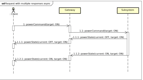
Figure 13: Synchronous request with multiple response sequence diagram
4.3.4 Request with Stream of Responses
Figure 14: Synchronous stream response sequence diagram
4.4
Other Hardware Control Systems
Throughout this study examples of the Thales use case are used. The results of this study can also be applied in a similar fashion to other hardware control systems. To illustrate this, we use the example of a high precision medical operating table. This table can be controlled by sending commands to the table, the table can be turned on and off and the hight of the table can be adjusted. The different conversation types can be translated for controlling the table:
• Request/response: Request the current hight of the table. The table will respond with one message indicating the current hight of the table.
• Request with fixed amount of responses: Turn on the table, similar to the Thales case a message is emitted when the table is turning on and when the table has turned on.
• Request with steam of responses: Command the table to rise, the table will emit messages about the current hight of the table with a fixed interval.
• Server push: When something is blocking the table a message can be emitted to notify the client that the table is not functioning properly.
4.5
Concluding Remarks
5
Implementation
This chapter describes the implementation of the protocol translations and the API gateway in the service-oriented architecture of Thales. The overall target architecture is described in Section 5.1. The implementation of the API translator component with protocol translations is described in Section 5.2. The implementation of the API gateway is described in Section 5.3. Concluding remarks are given in Section 5.4.
5.1
Target architecture
[image:34.595.58.537.482.672.2]This section describes the target architecture of the proof of concept implementation. The aim of the implementation is to introduce minimal changes to the original asynchronous component-based architecture while implementing a HTTP/REST interface with which the gateway/client can communicate. A diagram of the proof of concept architecture is shown in Figure 15, of which the green elements are the same as in the current existing architecture as shown in Figure 4 in Section 3.1. This means that the existing components are unchanged and still communicate using asynchronous messaging with a DDS. The proprietary API gateway component is replaced with an API translator component, which is indicated in yellow in Figure 15. This API translator component translates incoming HTTP/REST communications to internal messages. A HTTP/REST server is implemented in the API translator component which can be accessed by the API gateway. The blue elements in Figure 15 indicate the elements which communicate using HTTP/REST. For this research the Kong API gateway is used,which is justified Section 5.3.
The following sections describe the implementation process of the different new elements of this architecture. These sections describe the implementation of the API Translator component as well as the installation and configuration of the Kong API gateway.
Figure 15: Target architecture
5.2
API translator component
server block in Figure 15. This component handles the translations of the conversation types as described in Chapter 4. This section starts by describing the OpenAPI descriptions used to generate the server stub code and follows with the implementation of each conversation type in the translator component.
5.2.1 API Descriptions and Code Generation
Client and server side code can be generated by using an API description. For REST APIs this is commonly achieved by using OpenAPI descriptions [33]. Using this format, a REST API can be formally described, including its endpoints, operations and message schemas. An example OpenApi definition is described in Appendix A. An OpenAPI specification enables server and client code generation. For this project, the server stub is generated and is integrated in the API translator component. Customers can use the OpenAPI definition to generate client stub code in their language of choice, which facilitates the client side implementation and makes them less error prone. Due to the readability of the OpenAPI specification, it can also be an asset to the API documentation. Tooling is available to generate documentation based on the OpenAPI specification [40].
There are multiple server libraries written in C++ for which server stubs can be generated. Initially the choice was made to generate code for the Restbed library [14], which is an open source HTTP/REST server library written in C. Restbed was chosen as it supports a high number of features, but unfortunately it proved to be a challenge to integrate with the Thales architecture. This was mainly due an error in the library that occured with the configuration of Thales for which was not a solution at the time. Eventually the switch was made to the Pistache library [32], which proved to be significantly easier to integrate in the Thales architecture. An added benefit of Pistache is that is has no external dependencies and is developed with the aiming at high performance. Performance is not addressed in this chapter, but overall performance tests are described in Chapter 6.
5.2.2 Integrating Generated Server Code
The first step of the implementation was to integrate the generated server code into the Thales component-based architecture of Thales. During start-up of the system, the HTTP server is started by the API translator component. The generated server code provides skeleton functions which were implemented in this study. The implementation of the skeleton transforms incoming requests to messages to other components, or returns values based on (previous) messages. The API component should only provide basic transformations from REST to internal messages. Other features like logging, security and tracing are provided by the API gateway, of which the implementation is described in Section 5.3.
Listing 1: Generated code stub examples void D e f a u l t A p i I m p l : : p e r i o d i c t a s k i d t a s k u p d a t e g e t (
const i n t 3 2 t &i d ,
const P i s t a c h e : : O p t i o n a l<i n t 3 2 t> &v e r s i o n , P i s t a c h e : : Http : : R e s p o n s e W r i t e r &r e s p o n s e ) {
void D e f a u l t A p i I m p l : : p e r i o d i c t a s k i d t a s k s t a t e p a t c h ( const i n t 3 2 t &i d ,
const T a s k s t a t e p a t c h &t a s k S t a t e P a t c h , P i s t a c h e : : Http : : R e s p o n s e W r i t e r &r e s p o n s e ) {
5.2.3 Request/Response Implementation
The first implementation of a synchronous conversation is that of blocking request/response messaging. This means the client sends a request to the HTTP server and blocks until a response is received from the HTTP server. In this case the HTTP server always stores the latest version of the systemState, so that the state be directly returned. This is schematically shown in Figure 16. The state component emits the systemState to the API translator component, which stores this state in memory. This memory object is accessible by the HTTP/REST server, which can send the state as a response to the GET request.
[image:36.595.56.546.101.254.2]An alternative to this implementation is that the API translator component does not store the systemState in memory. In this case, the systemState should be requested from the state component when a GET request is received from the client. After a request from the client is received, a message is emitted to the state component to request the systemState. After a while the systemState is received by the API translator component and it is then sent to the client. The client is blocked while this communication takes place.
Figure 16: Request response implementation
5.2.4 Server push Implementation
[image:36.595.100.483.494.637.2]/api/sys-version of the systemState is already higher than than 4, the response is returned directly. If this is not the case, the response is blocked until the systemState is at the desired version. It is possible that the systemState does not change for a while and a timeout occurs on the connection. In this case the client will start a new request to receive version 4.
The server has to keep the connection open and wait for the systemState to change to the desired value. The implemented approach uses a condition variable with a lock to block the connection until the value has changed. The code for this approach is shown in Listing 2. This shows the request thread waiting for the modification id to be larger or equal than the requested version ’v’. The main thread notifies the request thread that the systemState has changed.
Listing 2: Long poll lock example
// Request thread
if( a p i . p l a t f o r m t a s k U p d a t e c o n d i t i o n v a r i a b l e . w a i t f o r ( l k ,
s t d : : c h r o n o : : d u r a t i o n<int>(60) ,
[this, v ]{return a p i . p l a t f o r m t a s k U p d a t e . m o d i f i c a t i o n i d >= v ;}) ){
r e s p o n s e . se nd ( P i s t a c h e : : Http : : Code : : Ok , g e t T a s k U p d a t e S t r i n g ( ) ) ;
} else {
// handle timeout }
// main thread
s y s t e m S t a t e c o n d i t i o n v a r i a b l e . n o t i f y a l l ( ) ;
In this design, the value is returned if the version of the value is higher than the requested value. This means that when version 3 is requested, a newer version (e.g., version 5) can be returned. This is a design choice, as in this case the newest version is always the most relevant. In a system where older versions are still relevant it is of course necessary to store and retrieve these past versions. This can also be very important if all versions need to be received by a client to allow for correct processing of all the information.
5.2.5 Request with Multiple Responses Implementation
Figure 17: Request with multiple responses implementation
Listing 3: powerCommand patch void D e f a u l t A p i I m p l : : powercommand patch (
const S t a t e p a t c h &s t a t e P a t c h ,
P i s t a c h e : : Http : : R e s p o n s e W r i t e r &r e s p o n s e ) {
a p i . sendPowerCommand ( s t a t e P a t c h . g e t T a r g e t S t a t e ( ) ) ; r e s p o n s e . se nd ( P i s t a c h e : : Http : : Code : : Ok) ;
}
5.2.6 Request with Stream Responses Implementation
The request with a stream of responses implementation is based upon the periodic task example, and the architecture for this implementation is shown in Figure 18. This conversation starts with a PATCH request to a task with a specific id. There are multiple predefined tasks, which can all individually be controlled by providing their id in the URL. There are two GET requests implemented, where one GET request is used to get the current state of the task. This indicates if the task is currently running or not. The other GET request is to get a taskUpdate for a specific task. In our example only one taskUpdate can be requested at a time. It is also possible to design a system in which multiple task updates can be returned using a single request. Once a task is enabled with a PATCH request the task will emits taskUpdates with a fixed interval.
Figure 18: Request with stream responses implementation
[image:38.595.104.486.577.711.2]updated. When the task is enabled, the taskUpdate message is emitted with a regular interval. For this proof of concept, this is simulated by a thread which emits a message every 4 seconds, of which the code can be seen in Listing 4. This code sets a random number in each message to simulate a changing value. A simple client can be created to test this implementation, which is a bash script with a loop that increases the version id, as can be seen in Listing 5. Sample output of this client is shown in Listing 6.
Listing 4: Task update thread void Task : : t a s k e x e c u t o r ( ) {
while( t a s k s t a t e . c u r r e n t s t a t e == platform ON ) {
t a s k s t a t e m u t e x . l o c k ( ) ;
t a s k u p d a t e . m o d i f i c a t i o n i d += 1 % INT MAX ; t a s k u p d a t e . t a s k v a r i a b l e = rand ( ) % 1 0 0 ; t a s k s t a t e m u t e x . u n l o c k ( ) ;
this−>p l a t f o r m t a s k u p d a t e s e n d T a s k U p d a t e ( t a s k u p d a t e ) ; s t d : : t h i s t h r e a d : : s l e e p f o r ( s t d : : c h r o n o : : s e c o n d s ( 4 ) ) ;
} }
Listing 5: Task update client for i in {0 . . 1 0 0 0 0}
do
c u r l h t t p : / / l o c a l h o s t : 8 0 0 0 / unauth / t a s k /1/ t a s k u p d a t e ? v e r s i o n=$ i done
Listing 6: Task update client output
{" task_id ": 1 , " task_variable ": 9 6 , " modification_id ": 2} {" task_id ": 1 , " task_variable ": 6 , " modification_id ": 3} {" task_id ": 1 , " task_variable ": 6 5 , " modification_id ": 4} {" task_id ": 1 , " task_variable ": 6 6 , " modification_id ": 5}
5.3
API Gateway
5.3.1 Installation
[image:40.595.55.540.303.482.2]The API gateway, management interface and database are running in Docker containers. For the Kong API gateway the open source management interface called Konga [34] is used. It is also possible to configure the Kong API gateway directly using the provided HTTP/REST API. The overall architecture is shown in Figure 19. This shows a simplified version of the component-based architecture on the right side with the new API translator component. Components in the component-based architecture can also be run as Docker containers, which allows for the whole system to run in Docker. The Kong API gateway communicates with a Postgres database to store its configuration and is accessible by two APIs on port 8000 and 8001. Kong can be configured using the API accessible on port 8001 and the client-facing API is accessible at port 8000. Konga communicates with the API on port 8001 to configure Kong. Konga provides a website on port 1337 which can be accessed with a browser. This website can be used to configure Kong.
Figure 19: Overall architecture
5.3.2 Configuration
Figure 20: Routes and services configuration
5.3.3 Security
Both Tyk and Kong provide a similar approach to security. In both, clients can be configured, and this configuration can be used to authenticate and authorize requests. They offer support for different kinds of authentication methods, such as: basic authentication (username/pass-word), key authentication and OAuth. For this example, key authentication was implemented to authenticate and authorize request. Key authentication requires a valid API key to be pro-vided within requests. An authentication key should be propro-vided in an URL parameter, such as for example: example.comapistate?key=some key. The API gateway then validates this API key on every request that passes through the gateway. In both Kong and Tyk, it is also possible to configure security certificates to encrypt traffic using SSL certificates. Both API gateways provide security features which are fully handled by the API gateway and fully transparent to the server.
Figure 21: Accessible routes for a client
5.3.4 Monitoring/Logging/Tracing
Both Kong and Tyk have in depth monitoring and logging features. Both provide plug-ins to log data to external services. Examples of available logging services (in Kong or Tyk) are file, TCP, HTTP or a service like Loggly. Monitoring plug-ins are also available, like Galileo, Datalog and Prometheus. Both management interfaces of Kong and Tyk provide a dashboard to get a quick indication of the state of the API gateway.
Most API gateways provide limited support for request tracing. Tyk does not support tracing features out of the box, but Kong does. To enable tracing in Kong, a Zipkin tracing service needs to be running. A Docker container is available with the zipkin tracing service, which works out of the box. The URL of the zipkin tracing service can be configured in the Kong tracing plug-in, which is everything needed to configure tracing. Figure 22 shows an example trace of a GET request to the state service. This trace shows the various stages the request passes through and the total time of the request. A sample ratio can be set, which only samples a percentage of the requests. This is useful to reduce delays when a lot of requests pass the gateway.
Figure 22: Zipkin trace example
5.3.5 Request/Response Transformation
[image:42.595.186.414.514.632.2]can only perform remove, rename, replace, add and append operations on the body, headers or query string.
Content-based transformations in the Kong gateway are only available with the enterprise plug-in. This reduces the applicability of the transformations in the free version significantly, since it is for example not possible to make changes based on request content. An example use case could be that internally the responses ’OK’ and ’NOK’ are used, but the customer requests that these responses should be ’successful’ and ’unsuccessful’, respectively. In Tyk this can be configured using the GO templates, in Kong this is not possible with the free version of the plug-in. It is possible to add the rule ’if a field called target state exists, set the value to ’successful”, but not ’if a field called target state exists and the value is ’OK’, change it to ’Successful’.
5.3.6 Request Composition
Tyk offers request composition which can be programmed in JavaScript files while Kong does not provide any request composition functionality. Ideally, request composition should be configurable, but in practice this is not available in open-source tooling. Both programming in Tyk or programming in C++ provide the disadvantage of programming over configuration which can introduce programming errors.
5.4
Concluding remarks
6
Results
In this chapter, the synchronous implementation is evaluated on several factors. The first factor is suitability, i.e. whether the new implementation addresses (most of) the challenges described in Section 3.2. The second factor is performance, in which benchmark tests have been executed to determine the performance of the new implementation. Lastly, design choices are discussed with possible alternative approaches to the problem. Section 6.1 describes the solutions for the different challenges, Section 6.2 analyses the performance of the system and Section 6.3 discusses the alternatives to the chosen solution.
6.1
Solutions to Challenges
Section 3.2 introduced the list of challenges with the current proprietary API gateway imple-mentation. These challenges have been tackled with the new API gateway impleimple-mentation. Below we discuss to what extend the implementation solves the challenges.
• Asynchronous client-facing and proprietary API:This study has introduced a syn-chronous API as an alternative to the currently asynsyn-chronous API. Using HTTP/REST as the communication protocol allows for widely available open-source tooling to be used to design and support the API. Examples of tooling that was used during this research are: the API gateway, OpenApi specifications, Server and client code generation, HTTP server framework in C++ and the benchmarking tooling. Client code generation allows for customers to easily generate HTTP client code in almost any language or framework of choice, which can reduce a large amount of implementation time.
The main challenge of the design for the synchronous API is to handle data pushed from the server to the client using synchronous methods. This was needed in multiple conversation types, specifically in the ’server push’ conversation type, but also in the ’request with multiple responses’ conversation type. There are several synchronous and asynchronous methods for pushing data from a server to the client. For this research the ’long polling’ method was chosen but other technologies like WebSockets or SSE are available alternatives for pushing data from the server to the client, but support for these technologies is limited in API gateways.
• User adaptations: User adaptations can now be configured instead of programmed by using the Kong Request and Response transformer plug-ins. Depending on the API gate-way, there is a limit to the number of changes that can be made to the requests. In case of the Kong API gateway, changes can be made to the body, header and query string us-ing the Remove, Rename, Replace, Add and Append methods. The Kong gateway only provides transformations based on the message payload for enterprise customers. The Tyk API gateway provides more in depth transformations by applying a template-based method using GO templates. The Kong API gateway has the advantage that transfor-mations can be configured using the GUI whereas in the Tyk API gateway knowledge about the GO template language is required.

![Figure 2: Netflix API gateway usage [25]](https://thumb-us.123doks.com/thumbv2/123dok_us/9651861.467196/10.595.172.420.594.741/figure-netix-api-gateway-usage.webp)
![Figure 3: Lyft using Envoy Proxy [30]](https://thumb-us.123doks.com/thumbv2/123dok_us/9651861.467196/12.595.59.573.451.697/figure-lyft-using-envoy-proxy.webp)