FE Magnetic Field Analysis Simulation Models based
Design, Development, Control and Testing of An Axial
Flux Permanent Magnet Linear Oscillating Motor
1
Govindaraj T
,
2Dr. Debashis Chatterjee
,
3Prof. Dr. Ashoke K. Ganguli
Abstract- Development, finite element(FE) analysis of magnetic field distribution, performance, control and testing of a new axial flux permanent magnet linear oscillating motor (PMLOM) along with a suitable speed and thrust control technique is described in this paper. The PMLOM can perform precision oscillation task without exceeding the given limit on allowable average power dissipation. The use of new powerful permanent magnet materials such as Neodymium-Iron-Boron alloys can greatly improve the performance of electrical machines. Also its performance parameters, such as the force, current etc. are experimentally assessed. The objective of this paper is to determine the forces for aluminium mover embedded with rare earth permanent magnet experimentally and analytically through FEMM software and develop a microcontroller based IGBT Inverter for its control.
Index Terms- Axial flux machine, finite element analysis, microcontroller based IGBT inverter, permanent magnet linear oscillating motor, rare earth permanent magnet.
I. INTRODUCTION
Many analytical and numerical techniques have been developed for the analysis of the end zones of electrical machine. The 2-D finite element method involves important computational means many efforts have been undertaken in order to use 2-D finite-element method FEMM.This paper presents different methodologies based on 2-D geometries using analytical solutions, This method has been implemented in conjunction with various geometry optimization techniques as it provides very fast solutions and has exhibited very good convergence with gradient free algorithms.
Manuscript received March 15, 2009.
1Govindaraj T is Ph.D. Research scholar with the Department of Electrical Engineering, Jadavpur University, Kolkatta 700 032, India (Phone 91 9865494551, E-mail ID:
[email protected], [email protected])
2 Dr. Debashis Chatterjee is with the Department of Electrical Engineering, Jadavpur University, Kolkatta 700032, India (Email ID:
3 Prof. Dr. Ashoke K. Ganguli is with the Department of Electrical Engineering, Jadavpur University, Kolkatta 700032, India (Email ID:
Interior permanent magnet motors are widely applied to the industry because of many advantages. Also the characteristics of magnetic materials are important to the performance and efficiency of electrical devices. Tradeoffs between accuracy, robustness and speed are central issues in numerical analysis, and here they receive careful consideration. The principal purpose of the work is to evaluate the performances of the PMLOM models when implemented in the FEM analysis of electrical machines. The developed methods are applied in a 2-D in-house FEM code, specialized for the design and analysis of electrical machines. The FEM simulations and the analysis on axial flux PMLOM, and the numerical results are validated experimentally. The techniques developed for the calculation of integral parameters involve particular assumptions and simplifications and present specific advantages.
LINEAR motors are finding increasing applications in different specific areas like high-speed transport, electric hammers, looms, reciprocating pumps, heart pumps etc.[1]-[7]. They are also well suited for manufacturing automation applications. Therefore, design of energy efficient and high force to weight ratio motors and its performance assessment has become a research topic for quite a few years. The permanent magnet linear oscillating motors (PMLOMs) are one of the derivatives of the linear motors in the low power applications having the advantage of higher efficiency. They can be supplied with dc or ac voltages [4]-[7] of which, the dc motors are having better efficiency due to the absence of the core losses.
although different other works [4], [7], and [8] dynamically estimate the inductance through FEM and field analysis [10] for getting the correct results. In this paper, the machine under consideration is an axial flux machine and the mover is having a non-magnetic structure, which is aluminium. Also the rare earth permanent magnets used in the mover are having a relative permeability nearly equal to unity and therefore the magnetic circuit under consideration will be unsaturated due to major presence of air in the flux path. Hence, consideration of constant inductance is quite errorless for such kind of machines, which also conforms to the experimental data shown later. Finally the machine is analyzed with the help of the field equations and solved for forces and resultant flux densities through FEMM [10] backed by suitable experimental results. A controller using PIC16F877A microcontroller has been developed for its speed and thrust control for successful implementation in the proposed application.
II. MACHINECONSTRUCTION
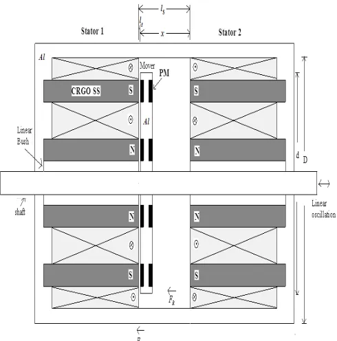
The construction of the prototype PMLOM is shown in Fig. 1 below. Also the dimensional details of the motor are shown in Fig. 2. There are two concentric coils on the surface of the stators connected in such polarities that the fluxes for both the coils aid each other to form the poles in the iron parts. The formation of the N and the S poles of the electromagnet of the stator are shown in the Fig. 2.
The mover consists of aluminium structure embedded with rare earth permanent magnets with the polarities as shown. The force developed will be attractive on one side and simultaneously repulsive on the other side. These two forces act in the same direction to enhance the total force on the mover, assisting the linear oscillation of the mover cyclically.
Fig. 1. Construction details of the developed PMLOM (i) Stators to be mounted on both sides of the mover and
[image:2.612.317.562.60.308.2](ii) the mover (iii) the PMLOM machine
Fig. 2. Dimensional details of the developed PMLOM
Al – Aluminium material PM-N42 Permanent Magnet
Attraction Force
F
A and Repulsion ForceF
RCoil 1 – aa’ and bb’ Coil 2 – cc’ and dd’
III. DETERMINATION OF TOTAL FORCE
Determination of the Attraction Force
Consider the Electromagnet and permanent magnet system in Fig. 2, Let us find the magnetic force between the electromagnet and permanent magnet poles,
F= Force between the Electromagnet and permanent magnet, N;
B= Flux density in the airgap,
Wb m
2;A= Area of magnetic pole,
m
2;If one of the poles is moved by a distance of
dx
, Work done = Fdx
.This work done is equal to the change of energy stored in magnetic field.Change in energy stored in magnetic field
= energy density
×
change in volume=
2
0
1
2
B
A dx
µ
×
=2
0
1
2
B
A dx
2
0
1
2
B
F dx
A dx
µ
∴
=
(2)2 2 0 0
1
0.051
2
B
B
or
F
A N
A kg
µ
µ
=
=
(3)
Hence from above, Force per unit area
2 2 2 2 0 0 (4)
1
0.051
2
mB
B
P
N m
kg m
µ
µ
=
=
The flux density in the airgap ,B, depends upon the mmf of the exciting winding and the permanent magnet. Let
AT
be the total mmf of the exciting winding. A portion of this mmf is required for the airgap and the rest for the iron parts of the magnetic circuit. LetAT
g be the mmf required for the airgapand
AT
i for the iron parts.H l
c m be the mmf of the permanent magnet.Now, 0 g g
AT
B
l
µ
=
, (5)where
c
H
= Coercivity of the Ring type Rare Earth Permanent Magnetm
L
=axial length of permanent magnet7
0
4
10
H m
µ
π
−=
×
g
l
= Axial airgap lengthx
= displacement of the mover at any point of time∴
From the (3), the Force(
)
2 20 0 0
1
1
2
2
g g g gAT
A
AT
F
A N
l
l
µ
µ
µ
=
=
(6)If there is no saturation in the iron parts, the mmf required for them is small and therefore
g
AT
=
AT
(7)This gives:
(
)
1(
)
2g c m c m
AT
=
AT
+
H l
+
AT
+
H l
(8)2 2
0 0 (9)
1
0.051
2
A g gAT
AT
F
A N
A kg
l
l
µ
µ
=
=
Referring to Fig. 2(a) and Fig. 2(b), when the polarities are opposite, the MMFs of primary coil and secondary PM assist each other, but when the polarity is the same, the MMfs of primary coil and secondary PM oppose each other. In these
machines the flux density,
B
can be increased to 1 tesla without saturating the core, in which case the force density becomes 57lb in
2 or4 10
×
5N m
2). Clearly this level of force density is very high. Permanent magnets, as an MMF source, yield a high air gap flux density and simplify the power supply system.Determination of Repulsion Force
Now, considering the repulsion force, we have the polarities of the currents reversed as shown in Fig. 2(b). The fluxes in the airgap are predominately radial. Qualitatively, it may be seen from Fig. 2(b) that we now have a force of repulsion between the coil and the permanent magnets. For a small airgap and for a uniform flux density in the airgap a simple magnetic circuit approach yields the magnetic stored energy.
Now
(
)
1(
)
2g c m c m
AT
=
AT
−
H l
+
AT
−
H l
(10)
2 0
1
2
RAT
F
A N
x
µ
=
(11)
IV. SIMULATIONANDEXPERIMENTALRESULTS
The proposed scheme is simulated under FEMM4.2 environment, which provides a finite element analysis. The machine specification used for both simulation and experiment is given in Table I.
The magneto static fields are provided by Maxwell’s equations
H
J
∇ ×
=
(12)0
B
∇ ⋅
=
(13) whereH
is magnetic field intensity,B
is magnetic flux density andJ
is the current density of the magnetic field. Subject to a constitutive relationship between B and H for each material:
B
=
µ
H
(14) Whereµ
denotes material permeability. Boundary conditions that must be satisfied at the interface between two materials having finite conductivities are,(
1 2)
ˆ
0
n
×
H
−
H
=
(15)(
1 2)
ˆ
0
n B
⋅
−
B
=
(16) Since the divergence of the curl of any vector must always be zero, it follows from (13) that there exists a so-called magnetic vector potential A such that,B
= ∇ ×
A
(17) Substituting (14) and (17) into (12) and taking a curl on both sides yields1
A
J
µ
∇ ×
∇ ×
=
(18)
Then,
A
=
Az
ˆ
(20) Thus, (18) reduces to,1
A
J
µ
−∇ ⋅
∇
=
(21)The above equation (21) may be written in the expanded form as,
1
A
1
A
J
x
µ
x
y
µ
y
∂
∂
∂
∂
+
= −
∂
∂
∂
∂
(22)This equation (22) represents the scalar Poisson equation.
FEMM retains the form of (18), so that magnetostatic problems with a nonlinear B-H relationship can be solved. The advantage of using the vector potential formulation is that all the conditions to be satisfied have been combined into a single equation. If A is found, B and H can then be deduced by differentiating A. The form of (18), an elliptic partial differential equation, arises in the study of many different types of engineering phenomenon.
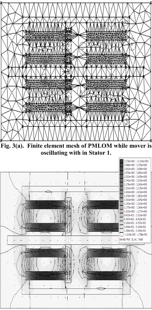
Fig. 3(a) shows the FEM mesh configuration for the PMLOM Prototype. Fig. 3(b) shows the Magnetic flux plotting of PMLOM while mover is oscillating within Stator 1, at 1 Hz, 4Amps. Figure 3(c) is the corresponding flux plotting of the machine while mover is oscillating within Stator 1, at 0 Hz. Fig. 3(d) illustrates the finite element analysis of the PMLOM at the axial airgap. Thus, the geometries of the mover and stator have been accurately discretized with fine meshes. Symmetry was exploited to reduce the problem domain to half of the axial cross section of the overall motor. The halved longitudinal cross section of the motor has created the calculation area, with Dirichlet boundary conditions (Fig. 3(d)). Thus, the magnetic field has been analyzed. For the calculations, material linearity of the NdFeB permanent magnet (
µ
r =1.048) was supposed. Its coercive force wasassumed to be
H
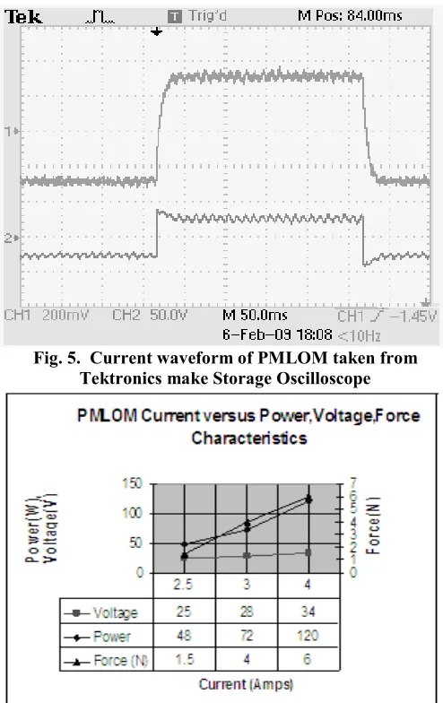
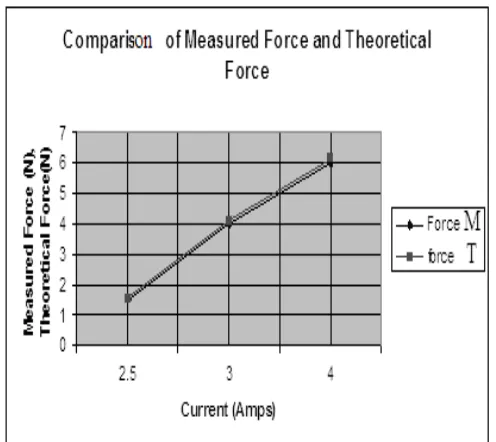
c= 925 KA/m and the magnetization vector direction were adopted for the calculations. Very small air gaps compared with the main motor dimensions between permanent magnets and ferromagnetic rings were neglected due to very small magnetic permeability of the permanent magnets, it is acceptable. The finite-element mesh (Fig. 3(d)) is dense in the air gap between stator cylinder sleeve and the mover. The fine mesh is also used near the edges of ferromagnetic parts where the magnetic field is expected to vary rapidly (Fig. 3(d)). In order to predict the integral parameters of the PMLOM, it is necessary to analyze the magnetic field distribution in the stator and mover. Obviously, it is possible to optimize the construction by making changes in the stator and mover geometries. The improvements of the structure result from knowledge of the magnetic field distribution. The presented results have been obtained for one variant of the motor construction. The control block diagram along with the experimental set-up power electronic control circuit is shown in Fig.4. Here the thrust control is provided with the help of phase controlled ac supply which can vary the input voltage. The frequency control is provided with the helpof a low cost and commercially available microcontroller PIC16F877A. The set-up is reliable and provides a scope for portability to any remote place. Fig. 5 shows the plot of the input voltage and current of the machine at 5 Hz. From which the assumption of constant inductance for the machine can be well validated. Fig.6 shows the characteristics plot of input power, voltage and force as a function of current for the machine taken at a frequency of 1 Hz. Fig. 7 shows Force at different axial airgap length. The Force observed by measurement is compared with the theoretical Force value and shown in fig. 8.
Fig. 3(a). Finite element mesh of PMLOM while mover is oscillating with in Stator 1.
[image:4.612.317.564.192.696.2]Fig. 3(c). Magnetic flux plotting of PMLOM while mover is oscillating with in Stator 1, at 0 Hz.
Fig. 3(d). Finite element Magnetic flux plotting at upper and lower part of the airgap while mover oscillates within
[image:5.612.51.295.51.497.2]stator 1.Now Mover is attracted to the Stator 1
[image:5.612.315.562.74.466.2]Fig. 4. Power Circuit of PMLOM
Fig. 5. Current waveform of PMLOM taken from Tektronics make Storage Oscilloscope
Fig. 6. Measured Coil current versus Power (W).Voltage (V), Force (N) Characteristics of PMLOM
Axial Airgap versus Force
0 2 4 6 8 10 12 14 16 18 20
3
3.5 44.5 55.5 66.5 77.5 88.5 99.59.5 98.5 87.5 76.5 65.5 54.5 43.5 3 Airgap (mm)
F
o
rce
(N
[image:5.612.62.282.541.698.2])
Fig. 8. Comparison of measured Force Versus Theoretical Force
TABLEI. PMLOMDESIGNPARAMETERS Rated Input Voltage 70V
Rated input power 175 watts
Stroke length 10 mm Outer Diameter (Stator) 85 mm
Stator core type CRGO Silicon Steel Thickness of lamination 0.27 mm
Stator length 60 mm
Number of turns in Coil aa’,cc’ 1000
Number of turns in Coil bb’,dd’ 500
Coil resistance 18 ohms
Slot depth 50 mm
Permanent Magnet Type Rare Earth N42, Nd-Fe-B Permanent Magnet Length 2 mm
Coercivity 925000 A/m Remanence 1.3 T Outer diameter (Mover) 65 mm
Shaft diameter 8 mm
Coil Inductance 0.18 Henry
V. CONCLUSIONS
A simple control method along with the development of an axial flux PMLOM suitable for low frequency and short stroke application is presented. Analytical solution to the forces and determination method of the integral parameters of a PMLOM are shown. Finite element method with FEMM4.2 is used for the field analysis of the different values of the exciting current and for variable mover position. Computer simulations for the magnetic field distribution, forces are given. To obtain experimentally the field distribution and its integral parameters, a physical model of the motor together with its electronic controller system has been developed and tested. The Prototype has been operated in the oscillatory mode with small loads at low frequency up to 5 Hz. The theoretically calculated results are compared with the measured ones and found a good conformity.
REFERENCES
[1] M. Athans and P. L. Falb, Optimal Control. New York: McGraw Hill, 1966.
[2] H. D. Chai, Electromechanical Motion Devices. Upper Saddle River, NJ: Prentice Hall, 1998.
[3] W. H. Hayt, Engineering Electromagnetics. New York: McGraw Hill, 1989.
[4] G. Kang, J. Hong, and G. Kim, “Design and analysis of slotless-type permanent-magnet linear brushless motor by using equivalent magnetizing current,” IEEE Trans. Ind. Appl., vol. 37, no. 5, 2001, pp. 1241–1247. [5] S. A. Nasar and I. Boldea, Linear Electric Motors. Englewood Cliffs, NJ: Prentice-Hall, 1987.
[6] B. Tomczuk and M. Sobol, “Influence of the supply voltage on the dynamics of the one-phase tubular motor . with reversal motion,” in Proc. 39th Int. Symp. Electrical
Machines—SME’2003, Gdansk/Jurata, Poland, Jun. 9–11, 2003, pp. 417–426
[7] N. Sadowski, R. Carlson, A. M. Beckert, and J. P. A. Bastos, “Dynamic modeling of a newly designed linear actuator using 3D edge elements analysis,” IEEE Trans.
Magn., vol. 32, no. 3, May 1996, pp. 1633–1636. [8] D. G. Taylor and N. Chayopitak, “Time-optimal position control of electric motors with steady-state temperature constraints,” in Proc.IEEE Int. Symp. Industrial Electronics, Montreal, QC, Canada, Jul. 2006, pp. 3142– 3146.
[9] S. Vaez-Zadeh and A. Isfahani, “Multi-objective design optimization of air-core linear permanent-magnet synchronous motors for improved thrust and low magnet consumption,” IEEE Trans. Magn., vol.42, no. 3, 2006, pp. 446–452.
[10] Finite element Method Magnetics, Version 4.2 User’s