Abstract - Degenerative neuromuscular diseases as muscular dystrophy may severely reduce the autonomous mobility of the subject’s limbs. Most subjects can recover some autonomy by means of external devices mounted on their wheelchairs. The helping devices can be active - generally motor driven - or passive. Sometime the active devices require a driving action of the contralateral upper limb. Following a specific request of some people, as first step of the research a simple and passive helping device has been designed, built and tested on subjects affected by muscular dystrophy (MD). The preliminary tests demonstrate that the prototype can increase the subjects’ upper limbs range of motion and that it is well accepted by the dystrophic patients.
Index Terms – counterweight, exoskeleton muscular
dystrophy, passive devices.
I. INTRODUCTION
Some degenerative neuromuscular diseases, such as dystrophy, affect muscles strength and force the subjects, few years after the appearance of the symptoms, to use power wheelchairs. In fact, not only the legs’ muscles become too weak to sustain the upper body weight during walking, but also the upper limbs’ become soon inadequate to power an ordinary wheelchair. At a certain stage of the evolution of the pathology, due to the lack of muscular strength, the upper limbs are not able to counterbalance gravity action, thus the subjects can only act, at the most, by moving the arm horizontally when it supported by a plane. The forced immobility produces a faster degeneration of the muscular structure. The recovery of some active mobility of the arm is then important both to carry out some autonomous daily activity and, to execute exercises working as self physiotherapy.
Assistive systems may help subject in this task: they can be active, that means in general motor driven, or passive. Some active system require to be driven by the controlateral limb - e.g. by replicating its movement or by means of an handled joystick – , originating unnatural movements [1] [2].
The present research was originated by the request of an organization – U.I.L.D.M. - , for the development of a passive system, at least for the preliminary stage. Most UILDM affiliated, up to now, prefer to avoid any motor driven device except for the electrical wheelchair on which they are forced to live.
Manuscript submitted March 21, 2008. All the authors are with the Department of Mechanics , Politecnico di Milano The corresponding author is Matteo Cocetta, ph.+390223998454 ([email protected]). The authors would like to thanks the members of UILDM (Unione Italiana Lotta alla Distrofia Muscolare) for the very effective cooperation .
Therefore, aim of the first part of the research is the development of a passive device as simple as possible, capable to enhance the upper limb mobility by acting against the gravity action. The device must be mounted on the frame of the subjects wheelchair.
II. PRELIMINARY TESTS FOR THE EVALUATION OF THE SYSTEM REQUIREMENTS
For what it concerns the classification of the level of impairment of the dystrophic subjects, presently the literature directly related to the analysis of the upper arm activity is very poor, all the classifications of the disease level and of the need of assistance is generally made evaluating the leg activity ( Vignos scale).
Therefore for the present research it was useful to set up a specific test to check the residual arm capability, to understand the strategies adopted by the subject affected by M.D. in order to better employ the scarce mechanical resources still available and to verify the influence of the apparatus under development.
The test set up includes a motion capture system used for tracking subjects’ upper body and arms (provided by infrared markers) and a wireless EMG system used to monitor the activity of some muscles.
A set of simple movements of shoulder and elbow has been acquired to classify the subjects and understand the requirements for the helping apparatus.
The Vignos Scale class 10 M.D. subjects have been sub classified in three new groups (tab.1) considering both the EMG activity and the joints’ range of motion.
TABLE 1: SUB-CLASSIFICATION OF M.D. PATIENT OF CLASS 10(VIGNOS SCALE)
initial intermediate advanced
EMG present small activity absent
Mobility present absent absent
To know the trunk kinematics and dynamics is essential to understand the arm performance.
The kinematic analyses show that some patients use the upper trunk and the scapula-clavicle complex to overcome the range of motion of the other joints of the limb, that is often too small even to perform very simple everyday actions.
Looking to the muscular activity it is evident, for instance, that some subjects activate the deltoid instead of the biceps to rise an handled object from a table, where the elbow is leaned. Consequently, for the design of any helping device it
A Passive Support To Motion Capability Of
Elbow angle (deg.) Torque
(Nm)
B C A
B1 C1 is important to let the shoulder free of any constraint.
[image:2.595.74.291.72.155.2]a b
Figure 1: EMG signals of bicep (a) and deltoid (b) of a MD subject during a hand lifting exercise
Another aspect of MD is the pathological deformation of the trunk due to the incorrect posture of the subject, loaded by head and arms weight. The permanent deformation of the chest involves serious breathing problems. Therefore, decreasing the arm weight transmitted to the shoulder, by means of an external device, it is profitable also by the breathing point of view.
III. TEST AND ASSISTIVE APPARATUS SET UP
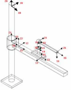
Starting from a kinematic model of the human arm [3] with 7 degrees of freedom - 5 d.o.f. for shoulder, and 2 d.o.f. for elbow -, a linkage system was designed to be coupled in parallel with the arm, avoiding to add constraints to the scapula-clavicle complex (Fig. 2). With this approach the device directly acts on the elbow, providing the counterweight force and couple for balance, leaving patience’s shoulder and trunk free to move. Thus the residual force becomes adequate to move the weight-compensated arm in its natural working volume, without any limitation of the motion due to the external device. The linkage includes two sliding (for horizontal and vertical translations) and one revolute pair. Weight compensation at the elbow is achieved by a spiral spring at the revolute pair, for the forearm torque, and by a counterbalance moving in vertical to compensate the whole arm weight. In order to balance the system, forces and couples have been evaluated as function of the arm position in space neglecting the inertia actions [4], which are very small in the range of motion typical of this application. The counterbalancing force F2 and the counterbalancing torque Mc (fig.3) can be simply obtained as follow:
F
F
F
F
V
+
2=
1+
3+
4 (1)0
)
sin(
)
AB
AC
(
F1
-)
sin(
AC
V
ϑ
ϑ
=
(2)thus, for balancing vertical actions:
4 3 1 2
AC
AB
-AC
-1
F
F
+
F
+
F
=
(3)and, analogously for balancing elbow torque:
)
sin(
CF
F
)
sin(
CD
F
M
C=
3ϑ
+
4ϑ
(4)The forearm counterbalancing torque (Fig.4 - blue line A)
[image:2.595.366.491.96.253.2]is only function of the elbow angle θ, otherwise counterbalance weight is independent from the arm position and both of them are functions of the subject weight .
[image:2.595.349.505.283.384.2]Figure 2: exoskeleton kinematic model
Figure 3: simplified scheme of loading actions on the arm
Figure 4: torque at the elbow
For the first prototype a spiral spring has been designed to follow approximately the torque diagram and the vertical guide has been equipped with little masses counterbalancing, through a cable and a pulley, the subject arm and the sliding structure weight.
Fig. 4 line B shows the torque exerted by the spring, line C the same with a spring preload, line B1 and C1 show instead, in both cases, the residual torque that the subject must exert to move the forearm.
While counterweights can be easily adjusted on patients’ weight and skill, spring action can only be tuned by varying the preload thanks to its adjustable support. Major variations of the torque can only be obtained by changing the spring.
[image:2.595.318.522.412.559.2]Figure 5: spring calibration: –blue continuous lines (B) not preloaded spring torque, dashed lines (C) preloaded springs torque (with 30° and 10° pre-adjustment) and red line required torque
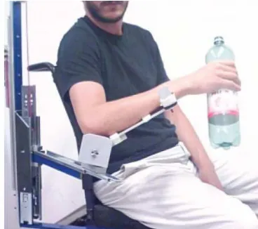
Figure 6: first prototype mounted on a wheelchair
IV. TESTING THE DEVICE
The first prototype of the developed device (Figure 6) has been tested with some patients to evaluate its effectiveness for helping them to move the arm and to handle simple objects for daily tasks (e.g. bring a glass to the mouth). The analyzed parameters are the changes produced by the external device to the joints’ excursions and to the trajectories followed by the hand to complete a task .
Test protocol set the exercise procedure that are executed by the patients seated in front of a table on a modified wheelchair without any initial training. Every task is executed three consecutive times, starting from simple movements of a single joint, to more complex exercises as to take a glass of water from a table and bring a it to the mouth. Markers on upper body (arm and trunk) are acquired by an infrared motion capture system together with the EMG signals of the most important muscles. Therefore the system’s kinematics could be reconstructed and correlated with the timing of muscular activity.
For the first series of tests a performance gain index was also extrapolated by comparing the results with the preliminary tests obtained without using the assistive device.
V. RESULTS OF THE TESTS WITH THE ASSISTIVE DEVICE
The results show that: the assistive device can increase the autonomy of people affected by M.D., the subject’s motion skills increase test after test and, moreover, in most cases the trunk posture improves.
In the following paragraph the results of some tests are displayed in terms of joint’s range of motion -r.o.m.- and of quality of the trajectory followed. (fig. 7 and 8).
[image:3.595.51.235.280.443.2]Figure 7: Example of arm joints excursion
Figure 8: Example of hand trajectory without and with the external device
All the tested dystrophic subjects are different, requiring a specific analysis and a specific adjustment of the assistive device nonetheless some preliminary rough indications can be withdrawn for all the group, considering that all the tested subjects are also using the wheelchair for a few years. The following example refer to a specific subject.
A. Exercise 1
Target movement Shoulder rotation to bring the forearm to the chest starting from a position where the elbow angle is 90° Involved muscles Deltoid , pectorals et al.
[image:3.595.305.490.321.429.2](fig.9 blue lines - where major trunk excursions are needed to the subject for overcoming the inadequate arm motion capability). With regard to the elbow movements, the helping device (Fig.10 red line) allows to move the joint more naturally and with a better repeatability if compared to the free arm case (Fig.10 blue line ).
[image:4.595.49.511.135.394.2]Figure 9: Exerc.1 - Upper trunk flexion and lateral bending
Figure 10: Exerc.1 - Elbow flexion
B. Exercise 2
Target movement Elbow flexo - extension Involved muscles Biceps, triceps
[image:4.595.49.293.421.550.2]The data collected during three consecutive repetitions of the movement show in all subjects a fast improvement of the performance, both for the r.o.m.(fig.12) and for the trajectory smoothness. The test of subject without any preliminary training show the ease of the device use (fig.11).
Figure 11: ex. 2 – Joints excursion with the device
Figure 12: exerc. 2 – Comparison of elbow max excursion
C. Exercise 3
Target movement Shoulder abdo-adduction Involved muscles Deltoid , pectorals triceps
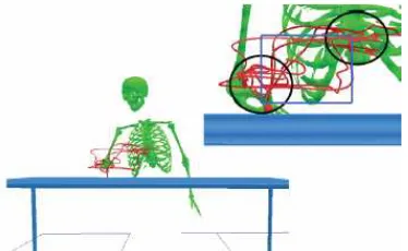
During this exercise the patient was asked to follow with the hand a rectangle in the frontal plane (fig.13 - blue line). Without the device the subject was unable to complete the task, while, with the assistive device the exercise was completed, even in presence f if two zones of indecision (fig.13 – black circles )
Figure 13: Exerc. 3 – Following a prescribed rectangular trajectory
D. Exercise 4
[image:4.595.306.493.489.604.2]Figure 14: joints laws of motion during drinking task
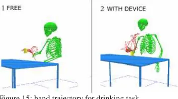
Figure 15: hand trajectory for drinking task
This particular task allows to verify overall the improvement of self-sufficiency obtained only by means of the assistive device. People most severely affected by M D, as most of the subjects tested for the present research, are unable to raise a glass from the table without any assistance. By means of the simple weight compensating system they can drink by themselves (Figure 15). Moreover a relevant correction of the trunk posture and an increase of mobility could be detected by analyzing the evolution of the joint law of motion . The graphs of the joint’s law of motion (Fig. 14) show ranges of variation similar to the physiologic ones. The kinematic analysis of the drinking movement with the device (fig.16 – dark blue line) shows that the trunk movement is kept much lower than the values recorded during the unsuccessful attempt to drink without help (fig.16 – light blue line). This can be interpreted as a corrective action for the body that allows more physiological movements.
Figure 16: trunk kinematics with (dark blue) or without (light blue) the assistive device during drinking task or drinking attempt .
VI. CONCLUDING REMARKS
The comparison of the tests performed with and without the prototype of the assistive device purposely designed for M.D. subjects highlights the relevant contribution that even this simple and passive device can produce to the upper limb
performance and consequently to the subject autonomy. The gravity action, counterbalanced by the exoskeleton system is in fact, for some people, the main obstacle to the course of many simple but important manual operations.
The kinematics and the EMG analyses are effective to optimize the assistive device parameters and the subjects residual capacity .
The present work is only a preliminary analysis of the assistive needs of M.D. subjects’ upper arm and shows one simple example of passive helping device to be mounted on the wheelchair. Its main features are to be simple and easy to use and not to add constraints to the natural movements.
The evolution of this passive system can lead new very useful products very profitable for dystrophic people. This system can be effective even when the residual force of the patient is low. Nonetheless when the force is rather null an active servo assisted device is needed. In this case, another problem to be solved would be the choice of the apparatus’ driving signal.
REFERENCES
[1] Perry, J.C.; Rosen, J.; Burns, S., "Upper-Limb Powered Exoskeleton Design," Mechatronics, IEEE/ASME Transactions on , vol.12, no.4, pp.408-417, Aug. 2007
[2] Kiguchi, K.; Tanaka, T.; Watanabe, K.; Fukuda, T., "Exoskeleton for human upper-limb motion support," Robotics and Automation, 2003.
Proceedings. ICRA '03. IEEE International Conference on , vol.2, no.,
pp. 2206-2211 vol.2, 14-19 Sept. 2003
[3] Keith Kubicek and Barbara Woolford, Anthropometry and biomechanics, Man-Systems Integration Standards Revision B, July 1995
[4] R. F. Chandler, C. E. Clauser, J. T. McConville, H. M. Reynolds, and J. W. Young. Investigation of inertial properties of the human body. Technical Report DOT HS-801 430, Aerospace Medical Research Laboratory, Wright-Patterson Air Force Base, OH, March 1975.
[5] Rocon, E.; Ruiz, A.F.; Pons, J.L.; Belda-Lois, J.M.; Sanchez-Lacuesta, J.J., "Rehabilitation Robotics: a Wearable Exo-Skeleton for Tremor Assessment and Suppression," Robotics and Automation, 2005. ICRA
2005. Proceedings of the 2005 IEEE International Conference on ,
vol., no., pp. 2271-2276, 18-22 April 2005
[6] Rahman T., Ramanathan R., Stroud S., Sample W., Seliktar R., Harwin W., Alexander M., Scavina M. 2001. Towards the Control of a Powered Orthosis for People with Muscular Dystrophy. IMechE Journal of Engineering in Medicine, Vol 215 Part H, pp 267-274. [7] Carignan, C.; Liszka, M.; Roderick, S., "Design of an arm exoskeleton
[image:5.595.48.291.547.674.2]