Abstract—Micro/nano positioning stages play an essential role in micro/nano precision technology, so the design and development of a new six-axis micro positioning stage are presented in this research. Based on Steward’s theory, the stage adopts negative Poisson’s ratio with flexure hinges. Since each of the axes is a planar mechanism structure, the stage is fabricated out of aluminum with the micro machining - a simple and well - developed fabrication technique for cost down and batch production. The stage consists of a top plate and a base plate, two hexagons of which the diameters are respectively 22 mm and 95.2 mm with a distance of 21.6 mm in between, and six trapezoid amplifiers, each of which is connected to the base plate at an angle of 30º. Each amplifier consists of three layers – two inner layers of symmetrical flexure hinges and one outer layer of non-symmetrical flexure hinge.
In this research, the stress, strain and amplification are calculated with the software of SolidWorks Ansys@. In experiment, each amplifier is driven by a piezoelectric transducer (PZT), and the displacements are measured with a laser displacement sensor and recorded for comparison of the single-axis amplifier with the six-axis stage. The results show that the amplification of the displacement of a single-axis amplifier is 15 times, that the horizon translation, the vertical translation, the tilt angle and the rotational angle are 50 μm, 50 μm, 0.5º and 0.5º respectively, and that the displacement resolution and the rotational resolution are 15.6 nm and 2.7 μrad respectively. It is obvious that the six-axis stage of this research, indeed, retains the features of high amplification and minimization, and is a novel and low-cost six-axis micropositioning stage.
Index Terms—Six-axis Micropositioning Stages, Negative Poisson’s Ratio, Flexure Hinge, Steward’s Stage.
I. INTRODUCTION
Along with the progress in industry technology, the development of micro/nano technology has become of great interest to precision technology, especially in fields like electron, communication, assembly, testing, and so on. However, it is hard to develop micro/nano technology through traditional series servo systems. Therefore, the design of a nano mechanism of high speed moving, high resolution and long travel as well as the adoption of a suitable actuator will definitely improve the precision of the stage.
Positioning stages, which play the role of loading and positioning an object, are generally expected to maintain a certain degree of stability so as to avoid making any noise in
K. H. Lin is with the Department of Mechanical Engineering, Ching Yun University Chung Li, Taiwan 320 (e-mail: [email protected])
Y. H. Hu is with the Department of Mechanical Engineering, Nanya Institute of Technology Chung Li, Taiwan 320 (She is corresponding author, fax: 886-3-4384670, e-mail: [email protected]).
vibration. The stages also need to retaincertain features such as high precision, long travel, mutil-DOF and high wideband control. In the application of micro/nano technology, the PZT, a device of small size, high resolution and high precision [1], is now the most frequently used device in the positioning system. However, since its motion range is very small, it cannot satisfy the requirement for long travel in many cases [2].
According to the literatures in the past decades, the ways to design precise positioning stages are roughly categorized as follows. One way is based on the multi-linkage mechanism theory, which is to make the stage move on an XYθ stage, with a device that connects a bar to a joint [3], such as a two-axis flexure hinge,or to make the stage move in 2-DOF, with a four-bar flexure parallel mechanism [4] to control the movement of the stage.In 2006, Chu [5] and his group, using a flexure hinge and a parallel elastic mechanism, succeeded in making a novel long-travel piezoelectric- driven linear nanopositioning - 50 μm in moving range and 10 nm in resolution. Another way is based on the kinematics theory, which is to use the magnetic field effect engendered by four sets of coils and four sets of magnets to control the kinematical motion – 100 mm in XY moving range, 200 nm in linear resolution, and 0.2” in rotational resolution.
No matter how many documents or records have shown efforts in designing and developing micropositioning stages, most of them are confined only to the development ofplanar motion stages integrated with XYθ.In this research, a six-axis micropositioning stage with 6-DOF is being designed and fabricated, based on Stewart’s theory of “A Platform with Six Degrees-of-Freedom” [7]. The concept of this design is derived from the material traits of the negative Poisson’s ratio [8] and the flexure hinge mechanism [9], trying to make a six-axis mechanism of negative Poisson’s ratio with flexure hinges [10]. It is a parallel mechanism of high stiffness, which can offer 6 degrees of freedom, with its size controlled under 100 mm x 100 mm x 30 mm, its linear resolution at 15.6 nm, and its rotational resolution at 2.7 μrad. Constructed with six parallel single-axis amplifiers, the stage does not add up the error from each single-axis amplifier and, therefore, is able to satisfy the requirement for high precision. Besides, with each of its amplifiers consisting of three layers – two inner layers of symmetrical flexure hinges and one outer layer of non-symmetrical flexure hinge [11], when actuated by the PZT, the stage can be used as a micro displacement stage of high precision. Finally, with the help of a commercial software package (SolidWorks Ansys@), we get to analyzekinematics and measure deformations based on the finite elements [12], and to calculate the amplification in numerical simulation and experiment. By comparing the
The Design, Analysis and Fabrication of
a Six-Axis Micropositioning Stage
deformation of numerical solutions, analytical solutions and experiment results in the algorithm of the six-axis stage, this research demonstrates the precision of the stage.
II. THE DESIGN OF THE SIX-AXIS STAGE
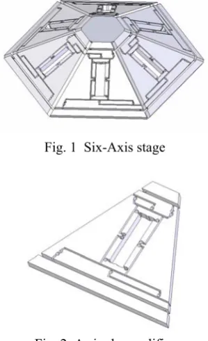
[image:2.595.372.474.194.288.2]As shown in Fig. 1, the six-axis stage designed in this research, with six PZT actuators driving the mechanism of negative Poisson’s ratio with flexure hinges, can generate a force to push all of the six amplifiers toward the center, minimize the gaps between the PZT actuators and the amplifiers, promote the precision of the mechanism and expand its displacement. It consists of a top plate (a hexagon of 22 mm in diameter and 3mm in height), a base plate (a hexagon of 95.2 mm in diameter and 3 mm in height), and six piezoelectric-driven displacement amplifiers which, respectively symmetrical to either of their neighboring ones, are all connected to the edges of the top and the base plates and meet the base one at an angle of 30º. The distance between the top plate and the base plate is 21.6 mm. Each of the amplifiers, as shown in Fig. 2, is a trapezoid, of which the shorter parallel side connected to the top plate is 12 mm, the longer parallel side connected to the base plate is 56 mm, the height is 44 mm and the thickness is 3 mm. Since each of the amplifiers consists of three layers – two inner layers of symmetrical flexure hinges and one outer layer of non-symmetrical flexure hinge, the three-layered amplifier mechanism can not only enlarge the amplification and enhance the spatial utilization ratio, but also minimize its frame size so as to achieve high amplification.
Fig. 1 Six-Axis stage
Fig. 2 A single amplifier
III. THE ALGORITHM OF THE SIX-AXIS STAGE
In this paper, the motion of the six-axis stage is discussed based on the global coordinate system (as shown in Fig.3). The system adopts two local coordinate frames: a base frame B and a plate coordinate frame P. Frame P consists of six
connection points (
P
i=
[
P
ixP
iyP
iz]
for і = 1 ~ 6) thatjoin the amplifiers to the top plate, whereas Frame B consists of six other connection points (
B
j=
[
B
jxB
jyB
jz]
for j [image:2.595.305.549.342.503.2]= 1 ~ 6) that join the amplifiers to the base plate. We use three translations and three rotations to make (x, y, z, α, β, γ) to indicate the relativity vector V of each point to Frame P and Frame B. Thus, we get the rotation matrix R as shown in Algorithm (1), where C = cos, S = sin, and the matrix {P} is included in
[ ]
Vρ.Fig. 3 A schematic diagram of the measurement global coordinate system. ⎥ ⎥ ⎥ ⎦ ⎤ ⎢ ⎢ ⎢ ⎣ ⎡ = ⎥ ⎥ ⎥ ⎦ ⎤ ⎢ ⎢ ⎢ ⎣ ⎡ ⋅ ⋅ − ⋅ + ⋅ ⋅ ⋅ − ⋅ ⋅ ⋅ ⋅ + ⋅ ⋅ ⋅ − ⋅ ⋅ ⋅ = ⎥ ⎥ ⎥ ⎦ ⎤ ⎢ ⎢ ⎢ ⎣ ⎡ − ⎥ ⎥ ⎥ ⎦ ⎤ ⎢ ⎢ ⎢ ⎣ ⎡ − ⎥ ⎥ ⎥ ⎦ ⎤ ⎢ ⎢ ⎢ ⎣ ⎡ − = = 33 32 31 23 22 21 13 12 11 1 0 0 0 0 0 0 1 0 0 0 0 0 0 1 r r r r r r r r r c c s c s s c c s s c c s s s c s s s c s c c s s s c c c c s s c c s s c c s s c R R R R γ γ γ Z Y X γ β γ β β γ α γ β α γ α γ β α β α γ α γ β α γ α γ β α β α γ β β β β α α α α (1)
Through the available coordinate trans- formation, we can get the translation vector of the amplifiers
L
ias:6 ~ 1 ] [ ] [ ] [ ] [ ]
[Li = R ⋅ Pi +V − Bi for i= (2)
where the displacement li as:
6 ~ 1
2 2
2 + + =
=
= L L L L for i
li i x y z (3)
IV. RESULTS AND DISCUSSION
A. Final StageResults of simulation and experiment on a single-axis amplifier
In this research, we use the software of SolidWorks@ to design and illustrate the mechanism and the software of ANSYS@ to simulate the analysis of a numerical scheme with finite elements on an unstructured grid. Fig. 4 shows the deformation of each single- axis amplifier when given a force of 10 N in the numerical simulation. The line indicates the location of the amplifier before deformation and the image shows the new location after deformation. In this single-axis amplifier simulation, the number of the elements is 347,235.
[image:2.595.93.243.432.678.2]To the single-axis amplifier, we suppose the longer parallel side of the trapezoid to be the fixed base (as shown in
Fig. 4). The force goes with uniform distribution from the center to the input points on the flexure hinge of the inner layer. (See B1 ~ B4 in Fig. 4. B1 and B2 are the input points
before deformation, while B3 and B4 are the ones after deformation.) The force increases from 1N ~ 20N, and the deformation is calculated every time after an increase by 1N. In Fig. 4, Point C on the lower left and Point D1, D2 on the
upper right are all output points. However, since the output point on the lower left is connected to the fixed base (see Point C in Fig. 4), its deformation is so small that it can be neglected. We only need to calculate the different values between D1 and D2, seeing that D1 is the output point before
deformation while D2 is the one after deformation. By calculating the differences between B1 and B3, B2 and B4,
and D1 and D2, we can get the displacement between the PZT and the amplifier. Nevertheless, we also calculate the linear deformation of the PZT as well as the spatial deformations of the amplifier at different forces, so that we can use them for the transformation of the six-axis stages later.
Fig. 4 The deformation at 10N in simulation In experiment, to promote the six-axis stage accuracy, each axis of the mechanism is fabricated out of aluminum (7075), using the micromachining system, of which the rotational speed of the spindle is 40,000 rpm, and the depth of cutting of each time is 0.05mm. Fig. 5 shows the single-axis amplifier in experiment. We place into the amplifier an NEC TOKIN AE0505D16 PZT of an appropriate size that gets the PZT perfectly stuck between the contact points at both ends without causing any deformation to the amplifier to supply voltages ranging from 0 to 100 V to the input points via the center, trying to enable the amplifier to extend outwards and generate various displacements. We use an image measuring system with resolution of 1μm to repeat each of the measuring processes at different voltages three times and record the displacements of the input and the output respectively, —each time with an increase of 10 voltages, so as to calculate the amplification. However, since the lower/bottom part of the mechanism (see Point A in Fig.5) is a fixed base, the displacement of Point C near the base is too small to measure even though the force goes with uniform to
both of the contact points (see Points B1 and B2 in Fig. 5).
Therefore, the displacement measuring end is the joining part of the flexure hinge. (See Point D in Fig. 5)
Each time, by capturing images, we measure the displacement at the upper part of the flexure hinge and calculate the relationshipbetween the PZT and the amplifier.
Fig. 5 A single-axis amplifier with a PZT in experiment
Fig. 6 indicates the difference between the simulation and experiment on a single-axis amplifier. The figure shows, when the input are respectively 5, 10 and 15 μm, we get the simulation deformations as 68.5, 137 and 205.5 μm, whereas we get the experiment deformations as 73, 153 and 233 μm. That is, with the same inputrange from 0 μm ~ 15 μm, for a single-axis amplifier, the average deformation results taken from the simulation and experiment are respectively 13.7 and 15 times as much, with an error of about 8.6%. We also see the results showing that, in the simulation, the ratio of the input forces to the input translations is 0.991387 μm/N, and that, in the experiment, the ratio of the input voltages of the PZT to the input transformation is 0.13 μm/V. Based on this, we can not only calculate the relationship of the input forces, the voltage and the elongation, but also set the parameters for the simulation and experiment of the six-axis stages.
0 50 Voltage(V) 100
0 100 200
D
e
for
m
at
io
n(
μ
m)
0 5 Force(N) 10 15
Experiment-Input Experiment-Output Simulation-Input Simulation-Output
Fig.6 The results of the input and output displacements of a single-axis amplifier in simulation and experiment
B1
D2
C
Before After
B2 B3
B4
D1
A
A
B1
B2
C
B. Results of simulation and experiment on a six-axis stage
Since the six-axis micro mechanism designed in this research is to be applied to the precise micropositioning systems, such as optical fiber alignment system. With such a micro adjustment device, the maximum vertical translation, horizontal translation, tilt angle and rotational angle here are set as 50 µm, 50 µm, 0.5º, and 0.5º. Applying these parameters to Eq. (1) ~ (3), we get the calculation of the displacements of each amplifier (as shown in Table 1).
Table 1 The displacements of each amplifier Vertical
translation 50 μm
Horizontal translation
50 μm
Tilt angle
0. 5°
Rotational angle
0. 5° 1staxis 154.8577 122.7628 123.8897 203.6697 2nd axis 154.8596 161.0910 119.4709 86.6524 3rdaxis 154.8614 151.4423 140.5646 203.6726 4th axis 154.8614 151.4423 149.6574 86.6553 5thaxis 154.8581 161.0899 170.9690 203.6712 6th axis 154.8577 122.7628 166.2962 86.6512 To compare their numerical solutions, analytical solutions and experiment results, we calculate the relationship from Fig.6 through interpolation and get the deformations as shown in Table 1. After that, we transform the deformations from Table 1, we obtain the resultant forces and voltages of the six-axis stages in simulation and experiment as shown in
Table 2 and Table 3.
Table 2 The input forces of the six-axis stage in simulation Vertical
translation 50 μm
Horizontal translation
50 μm
Tilt angle
0. 5°
Rotational angle
0. 5° 1staxis 11.4118 9.0466 9.1297 15.0088 2nd axis 11.4119 11.8711 8.8040 6.3856 3rdaxis 11.4120 11.1601 10.3585 15.0090 4th axis 11.4120 11.1601 11.0285 6.3858 5thaxis 11.4118 11.8710 12.5990 15.0089 6thaxis 11.4118 9.0466 12.2547 6.3855
Table 3 The voltages of the PZT in experiment Vertical
translation 50 μm
Horizontal translation
50 μm
Tilt angle
0. 5°
Rotational angle
0. 5° 1st axis 83.302 66.037 66.643 109.559 2ndaxis 83.303 86.655 64.266 46.612 3rd axis 83.304 81.464 75.613 109.560 4thaxis 83.304 81.464 80.504 46.641 5th axis 83.302 86.654 91.968 109.560 6thaxis 83.302 66.037 89.455 46.612
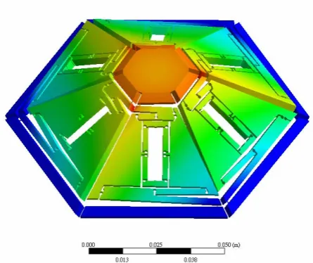
With the input forces shown in Table 2, we then analyze the numerical simulation of the six-axis stage. We apply fine meshes to the parts where flexure hinges are located so as to perform finer analysis and medium meshes to the others. The number of meshes is totally 649,457. Of the six-axis stage, the fixed planes are the base plates (shown as the blue parts), and the measure planes are the top plates (the red parts—red
suggests where bigger displacement takes place). In simulation, each of the six input forces of the amplifiers goes with uniform distribution from the center to the contact points on the flexure hinges of the inner layers, as that of a single-axis stage does, only this time with a downward load of 1N added to each of the top plates. Fig. 7 ~ 10 show the simulated deformations of the six-axis stages respectively with varied vertical translations, horizon translations, tilt angles and rotational angles.
Fig. 7 Simulated deformations of the six-axis stages with varied vertical translations
Fig. 8 Simulated deformations of the six-axis stages with varied horizon translations
Fig. 10 simulated deformations of the six-axis stages with varied rotational angles
Fig.11 shows a six-axis mechanism in experiment. Each of the amplifiers has a PZT placed in the center; the base plate is the fixed plane and the top plate is the measure plane. When supplied with the voltages stated in Table 3, each of the PZT actuates its amplifier to extend outward so that the top plate can move to the expected position.
Fig. 11 The six-axis stages in experiment
[image:5.595.47.275.370.513.2]We set a laser displacement sensor on a small coordinate measuring machines(CMM) and mark the symmetric points on the top plate of the stage. Then four different motion deformations of the stages are measured after each PZT is supplied with the voltages shown in Table 3.Table 4 shows all the expected results and the errors in simulation and experiment respectively.
Table 4 The comparison between the results and errors in simulation and experiment
Vertical translation
Horizontal translation
Tilt angle
Rotational angle
Expected results 50 μm 50 μm 0. 5° 0. 5° Simulated results 49.4 μm 44.8 μm 0.462° 0.45°
Simulated errors 1.2 % 10.4 % 7.6 % 10 % Experimental results 49.28 μm 44.7 μm 0.447° 0.442° Experimental errors 1.44 % 10.6 % 10.6 % 11.6 %
The results in both simulation and experiment show that, except that the errors in the vertical translations are under 1.5%, all of the other errors are around 10%. The reason might be that there is no restriction on the directions of displacement with a single-axis amplifier, whereas with the six-axis stages, the vertical, horizon and rotational displacements altogether need to keep the top plate horizontal, the tilt displacements need to make the top plate tilt symmetrically and no interference from the six amplifiers is allowed with one another. All these cause restriction onto the amplification and, therefore, make it hard to reach the expected range. However, when applied to manufacturing in the future, a linear scale will be built into this mechanism, and the errors in displacements can be better controlled so as to promote its precision.
V. CONCLUSION
With the mechanism of negative Poisson’s ratio with flexure hinges, this research designs and fabricates a six-axis mechanism for simulation and experiment. This mechanism consists of a top plate, a base plate and six amplifiers. The top plate is a hexagon of which the diameter is 22 mm and the thickness is 3 mm, and the base plate is a hexagon of which the diameter is 95.2 mm and the thickness is 3 mm, with a distance of 21.6 mm between the two plates. Each of the amplifiers consists of three layers—two inner layers of symmetrical flexure hinges and one outer layer of non-symmetrical flexure hinge. The stage is manufactured of aluminum (7075) through micromachining.
Both of the results in simulation and experiment on a single-axis amplifier show that, with inputs from 0~15 µm, all of the amplifications are about 15 times with error under 8.6%, that the relation between the forces and the inputs is 0.991387 µm/N, and that the relation between the voltages and the inputs is 0.13 µm/V. Yet, the results in simulation and experiment on the six-axis stages show that, with the vertical translation, horizon translation, tilt angle and rotational angle respectively at 50 μm, 50 µm, 0.5º and 0.5º, only the error in vertical translation is under 1.5%, that the errors of all the other motions are about 10%, and that, with the mechanism being 100 mm x 100 mm x 30 mm, the deformation resolution is up to 15.6 nm and the rotational resolution 2.7 µrad. This indicates that the six-axis stage of this research, indeed, retains the features of high amplification and minimization. Our next target will be the application of the long travel nano stage in future.
ACKNOWLEDGMENT
[image:5.595.46.293.667.755.2]REFERENCES
[1] Q. Yao, J. Dong and P. M. Ferreira, “Design, analysis, fabrication and testing of a parallel-kinematic micropositioning XY stage,” Mechine tools and manufacture, Vol. 47, pp. 946-961, 2007.
[2] W. J. Kim, S. Verma and H. Shakir, “Design and precision construction of novel magnetic-levitation- based multi-axis nanoscale positioning systems”, precision Engineering, Vol. 31, pp. 337-350, 2007. [3] Y. Wu and Z. Zhou, “An XYθ mechanism actuated by one actuator”,
Mechanism and Machine Theory, Vol. 39, pp. 1101-1110, 2004. [4] H. H. Pham and I. Chen, “workspace and static analyses of 2-DOF
flexure parallel mechanism”, Seventh International Conference on Control, Automation, Robotics and Vision, pp. 968-973, 2002. [5] C. L. Chu and S. H. Fan, “A novel long-travel piezoelectric-driven
linear nanopositioning stage”, Precision Engineering, Vol. 30, pp. 85-95, 2006.
[6] W. Gao, S. Dejima, H. Yanai, K. Katakura, S. Kiyono and Y. Tomita, “A surface motor-driven planar motion stage integrated with an XYθZ surface encoder for precision positioning”, Precision Engineering, Vol. 28, pp. 329-337, 2004.
[7] Stewart, D., A Platform with Six Degrees - of - Freedom, Proc. Inst. Mech. Eng., Vol. 180, No. 1, pp. 371-386, 1965.
[8] Sigmund, O., Tailoring materials with prescribed elasticproperties, Mechanics of Materials Vol. 20, pp. 351- 368, 1995.
[9] Trease, B. P., Moon, Y. M. and Kota, S. Design of large-Displacement Compliant Joints, Trans. of the ASME, Vol. 127, pp.788-798, 2005. [10] Lin, K. H., Hu,Y. H. Huang, C. M. and Fu, C. J, Design and Numerical
Simulation of Piezoelectric Micro-Platform, Journal of Ching-Yun University, Vol. 26, No. 1, pp. 25-34, 2006.
[11] Sigmund, O., Tailoring materials with prescribed elasticproperties, Mechanics of Materials Vol. 20, pp. 351- 368, 1995.
[12] Gao, P and Swei, S. M., A six-degree-of -freedom micro-manipulator based on piezoelectric translators, Nanotechnology, Vol. 10, pp. 447-452, 1999.