Abstract—In this paper, a methodology for solution of transient thermal problem is presented using finite-element method. A vertical hollow circular cylinder is heated up to a specific temperature using moving induction heating, and the heated parts then quenched by moving water-air spray. The effects of natural convection with air on the both inner and outer surfaces of cylinder, and also radiation of outer surface of cylinder with ambient, on cooling process are taken into account.
The transient thermal conduction equation is solved to obtain temperature distribution produced by the moving heat source in work-piece over time with considering of moving free and forced (due to spray) convection boundary conditions. This procedure includes temperature-dependent properties.
For quenching of work-piece, a specific kind of atomized spray cooling is used. Spray cooling using a mixture of water and air with different mass fractions; hence, with spray cooling, one can raise or lower the cooling rate by increasing or decreasing the amount of liquid in the mixture.
Keywords— water-air spray, cooling process, finite-element method, vertical hollow cylinder, temperature distribution
I. INTRODUCTION
uenching from high temperatures is usually performed on steel to produce high strength levels. However, in medium carbon, high carbon, and alloy steels, these rapid cooling rates may lead to formation of cracks. Spray cooling offers an attractive alternative to uncontrolled rapid quenching for thermal processing of steels, and widely used in today’s industrial operations including surface hardening, melting, brazing, welding, forging and other similar applications. It is used in a variety of engineering and materials processing applications in the automotive, aerospace and some others. With spray cooling, one can raise or lower the cooling rate by increasing or decreasing the amount of liquid in the mixture. When work-piece is heated to a specified temperature, it must be quenched. The quality of cooling is a specified problem by itself, and is a complex process. Because, as said before, hardness of steel after heat treatment depends on the time of
H.Shokouhmand, Professor of School of Mechanical Engineering, College of Engineering, University of Tehran, Tehran, Iran ( e-mail: hshokoh@ ut.ac.ir). S.Ghaffari, M.S. student School of Mechanical Engineering, College of Engineering, University of Tehran, Tehran, Iran (corresponding author to provide phone: 00989125031913; e-mail: sghaffari@ ut.ac.ir).
cooling. So, cooling of heated body is an important and sensitive part in heat treatment, and should be studied carefully. Spray cooling using a mixture of water and air was found useful in controlling the cooling rate of hot medium-carbon steel bars. With spray cooling, one can raise or lower the cooling rate by increasing or decreasing the amount of liquid in the mixture. The atomized spray consists of small liquid droplets in a conical jet of air. In this application, water is the liquid of choice because of its low cost. However, many literatures have been made for single-phase cooling [1-3], papers for spray-cooled surface at a high temperature are so limited. Because, at the high temperatures flow becomes multi-phase, and the heat-transfer relations are not well established as they are in single-phase flow. In the other words, Spray cooling is a new discussion in high-heat flux cooling[4]. Buckingham and Haji-Sheikh [5], described the heat transfer characteristics of a spray-cooled surface of cylinder at a high temperature before the onset of surface wetting phenomena. Experimental heat flux data are presented for different liquid mass fractions, and at surface temperatures up to 1000 C. Thomas and Haji-Sheikh [6], presented finite-element modeling and experimental verification of spray-cooling process in a steel cylinder from an initial temperature of 1273K. They also demonstrated the prediction of quench cracks with commercial finite-element analysis (FEA) using available information on a complex heat-transfer phenomenon like spray cooling. The temperature fields predicted by the model are used as an input for the thermal-stress model to predict the occurrence of quench cracks.
In this publication, the analysis of cooling process of a heated cylinder which is heated up using moving heat induction is investigated. It means, the magnetic field is first simulated by means of solution of maxwell’s electromagnetic field equations, and the moving heat source is obtained from this magnetic field.
The review of the previous works showed that some studies were conducted on analysis of moving induction heating problem to investigate temperature distribution during the heating process and they didn’t engage in subsequent quenching process sufficiently. However, according to the authors’ knowledge, there is no study of thermal analysis of moving induction heating with prefect investigation of cooling process. The coupled magnetic and thermal problem in a vertical hollow circular cylinder must be solved, because the material properties in the induction heating depend on the temperature.
Thermal Analysis Of Cooling Process Of A
High-Temperature Vertical Hollow Cylinder
Using A
Water-Air Spray
H.Shokouhmand, S.Ghaffari
*Th ve
Th m at of Si sy in
A
To du m cu th w in
1
µ
W cu co fr Th EF sh
A Fo co A
1
µ
A
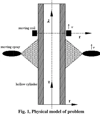
he basic arra ertical hollow
he inductor m moving spray m
t the same vel f the heated pa ince this inve ymmetric, the n fig.2.
A. Analysis o
o evaluate th uring inductio magnetic vecto urrent flowing he maxwell’s e with the approp n cylindrical co
1 (
1
2 2
∂ ∂ + ∂ ∂
r A r r
A
µ
Where
A
is th urrent density onductivity an equency ofω
he boundary FGHIJE suffi hown in fig.20 =
A
or the arrange oil of strength
) ,
( 2
1 R z A
A i =
, ( 1
1 0
z R A
r i
∂ ∂
µ
) , (
2 R z A
A O =
II. GOVER
[image:2.595.82.250.133.325.2]angement of cylinder is de
Fig. 1, Physic
moves at a velo moves with a s locity with it art.
estigated arran domain of so
of electro-mag
he heat sourc on heating, it or potential i g through the
electro-magne priate bounda o-ordinates be
2 2 2
− ∂ ∂ +
r A z
A r A
he magnetic v y,
µ
is the nd for a sinusof
π
ω
=
2
.y condition iciently distan
[7-8], holds: ement shown i
S
J , the other
) , (Ri z
( 1
) A2
r z
∂ ∂ =
µ
) , (3 RO z
RNING EQUATIO
moving indu epicted in Fig.
al model of prob
ocity of
v
alo specific distanto assure con ngement may olution can b
gnetic field:
es generated t is first nece in the induction co etic field equa ary conditions ecomes:
)−i
ωσ
A+Jvector potentia permeability oidal source cu
along the nt from the cy
in Fig. 2 and f boundary con
) , (Ri z
ONS
uction heatin .1.
blem
ong the cylind nce to the indu nsequent fast y be consider e modeled as
within the m essary to obt -piece relevan oil. For this p ations must be s. It for our p
0 = S
J
al,
J
S is the y,σ
is the urrent with aartificial bo ylinder and in
for a delta-fun nditions are
ng of a
der. The uctor at cooling red
shown
material tain the nt to a purpose, e solved problem (1)
source electric angular
oundary nductor (2) nction
(3) (4)
(5)
1
µ
W
µ
Th
g&
W po
B
Th du qu co he str C
ρ
Sin ord C
ρ
W spe Ce eli the
C
r
W co
, (
2 R z
A
r O
∂ ∂
here the subsc
0
µ
is the permeF
herefore heat s
* 2
2 1
AA
σ
ω
=here
A
* is th otentialA.B. Analysis of
he calculation uring the m uenching requ nvection and at conduction rength
g
&
is exp k t T Cp ∂ =∇∂ .(
nce our probl dinates can be r r t T
Cp ∂
∂ = ∂
∂ 1
here
k
is t ecific heat. eramic rings w iminate heat l ere is no heatC. Boundary
: −
=Ri k
here
T
∞ is nvection heat1
) 3
0
A r
∂ ∂ =
µ
[image:2.595.313.542.144.354.2]cripts represen eability of air.
Fig. 2, Domain o
source can be
he complex con
of thermal field
n of the temp moving induc uires a solut
radiation bo n equation fo pressed as [9]
g T k∇ )+ &
lem is axi-sym e written as:
z r T kr
r ∂
∂ + ∂ ∂
) (
thermal condu were attached loss and they transfer from
conditions fo
) , ,
( =
∂ ∂
r t z R T i
ambient tem t transfer coef
) , (RO z
nt the regions
of solution of pro
expressed as:
njugate of the
d
perature distr ction heating tion of the h undary condi or a solid wit
:
mmetric, Eq.(
g z T k∂∂ )+ &
(
uctivity,
ρ
d to both end y works as inlines AB and
or internal surf
( )
1[ ( ,= hc T Ri
mperature and fficient with a
shown in fig.
oblem
e magnetic vec
ribution in cy g and subs heat equation itions. The tra th a heat sou
8) in cylindri
is density, ds of the cylin
nsulators. The CD.
rface
] ) ,t −T∞
z
d
( )
h
c 1 is n air as shown in(6)
2; and
(7)
ctor
ylinder sequent n with ansient urce of
(8) cal
co-(9)
p
C
isnder to erefore,
Th
(
hD
Th by m by co on su ea re he th re co co
+
r
h
W ou th he St an Th su qu
+
r
Th re
he convection
)
W [image:3.595.130.241.123.301.2]hc 1=20 /
Fig. 3, Pr
D. Boundary
he cooling pro y three differe main parts in c y moving coo onvection with n reduction o urface of cylin ach time step: egion that isn’
eat transfer co han natural con esult in for the
onvection ca onditions for t
, , ( [
:
+
− =
t z R T h
k R
O r
O
( ( 2
= T RO
r
σε
Where
( )
h
c 2 i uter surface d he details.T
jeat transfer co tefan–Boltzma nd
ε
is the mhe cylinder s ubjected to nat uenching proc
, , ( [
:
+
− =
t z R T h
k R
O r
O
he initial cond egions of cylin
n coefficient K m2. .
resentation of B
y conditions fo
ocess on outer ent forms. The cooling proce oling ring. So h adjacent air of temperatu nder can be d
the region ex t influenced b oefficient due nvection heat e region expos an be negle
this region are
] )
) , , (
∞
− ∂ ∂
T r
t z R T
k O
) ) , ,z t +T∞2
O
is forced conv due to spray c is the jet st oefficient that ann constant material emissi
surface regio tural convecti cess:
] )
) , , (
∞
− ∂ ∂
T t
r t z R T
k O
dition for the t nder is:
for air cooli
oundary conditi
for external su
r surface of cy e most import ess is forced c me other mec and radiation ure of work-p
divided into tw xposed to cool by cooling ring
e to cooling r transfer coef sed to cooling ected. Theref e:
( )
2[ (= hc T RO
) , , (
)(T RO z t +
vection heat tra ooling that is tream tempera t is defined b
that is 5.67
ivity coefficien on not expos
ion with air du
( )
[ ()
1
= hc T RO
temperature fi
ing was assum
ions in problem
rface
ylinder is esta tant of them t convection pr chanisms are n that have les
piece. Hence wo different p ling ring, and g. Forced con ring is much fficient with a g the effect of
fore, the bo
] ) , ,z t −Tj O
)
∞
+T
ansfer coeffic discussed lat ature,
h
ris ra by Eq.(12).σ
8
. 10
7× − Wm
nt.
ed to cooling uring the heat
] ) , ,z t −Tj O
ield within the med as
ablished that has roduced natural ss effect e, outer
parts in the dry nvection greater ir. As a f natural oundary (11)
(12) cient for ter with adiation
σ
is the4 2
. − −
K
g were ting and
(13)
e whole
T
Th can is the ste exp
E d
Th co at ph flo exp use for
BE
No wa co
By on W ma pro reg wh en bo co fro of sin Th ev [9]
0
)
0
,
,
(
r
z
=
T
he calculation n be carried o attached to th e same mesh c ep, the positio
posed to natur
E. Evaluation due to spray c
he atomized nical jet. Sinc
high tempera hase flow. In a
ow heat trans perimental re ed for obtaini r outer surfa
X
ETE
1
/
4
′′
ozzle Inc.[6], ater in an ann nical spray. S
F
y increasing o ne can increas With presenting ass-flow rate ocess during s gions:
1) Radiatio
hen surface te nergy evaporat oundary layer ol the surface om the cylind
air and wate ngle-phase mo he heat-transf
aluated using ]:
0
of the temper out in a movin he moving co can be used a n of coil, posi ral convection
n of forced co cooling
spray consist ce spray cooli atures, the he addition, nume sfer is very c elations for sp ing forced co ace due to s
PR
XA
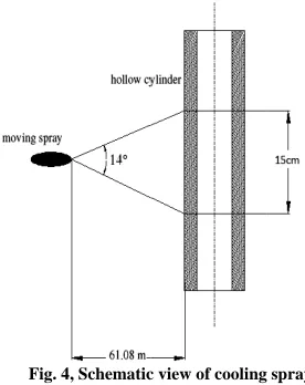
150
which intern nular region w
[image:3.595.350.488.377.551.2]chematic view
Fig. 4, Schematic
or decreasing t se or decrease g
X
, that is d to the air-m spray coolingon-dominated
emperature be tes all of the w and the mixtu e by convect der is by radia er vapor as s odel can pred fer coefficient equation for s
rature field w ng co-ordinate oil, where
λ
=
at each time st ition of movin n must be updnvection heat
ts of small l ing process fo eat transfer e erical investig complicated. T
pray cooling p nvection heat pray cooling
B
manufact nally mixes c within the no w of nozzle isc view of cooling
the amount of e the cooling defined as the mass-flow rate can be divide
region:
ecomes high water droplets ure of air and v
ion. In this r ation and conv said before in dict the conve t at the stagn single-phase f
ithin the work e system
(
r
,
λ
vt
z
−
=
. Thetep. So, in eac ng spray and r dated.
t transfer coeff
iquid droplet or heated part establishes in gation of multi Therefore, av process of ste t transfer coef g. With consi tured in Bet compressed a ozzle to form shown in fig.
g spray
f liquid in the rate at the s e ratio of the e. The heat-tr ed into three s
enough that r s before reach
vaporized wat region, heat tr
vection to a m n Eq.(23). He
ection heat tr nation point c flow over a cy
(14) k-piece
)
λ
that erefore, ch time regionsfficient
ts in a occurs
multi-i-phase vailable eel are fficient idering te Fog air and
a fine .4.
e spray, urface. water-ransfer pecific
radiant ing the ter will ransfer mixture ence, a ransfer.
R h − W R In th is di Bi th ai
(
T
te [1T
Th wT
In dr tra re be at hC W A re bo po h0 W eq C ou tra foco
h
(
10 256 . 3 82 [ 2 9 0 , O m R R k × − = − Where Reynold(
a m u 1Re =
ρ
0n above equati he viscosity an density of a istance of cyli ird et al. hermophysical
ir and water c
)
,
,
(
R
Oz
t
T
+
mperature, an 11]:
T
T
j=
∞+
5
°
his condition where
T
maxis cmax
125
T
=
+
2) Convect
n the convec roplets mainly ansfer to the each the surfa
egins when
T
(
t the stagnation5 0 , 10 9 . 1 C × =
Where
k
a is th3) Transiti
A transition re egion, the dro
oundary layer oint in this reg
+ =hR,0 hma
0 (
Where
h
maxis qualsT
max.onsequently, uter surface du ansfer coeffic ollows, [6]:
(
04
2
cos
os
1
5
.
0
1
[
C
h
−
+
=
θ
θ
(
Re Pr)
0030 . 0 81 . 2 33 . 0 m m× +
ds number
Re
)( )
m
T R X 2 0
µ
+ions
k
m,µ
m nd prandtl num air,u
0is max inder,T
sat is t [10] presen l properties oonsidered at m
2
/
)
j
T
+
, wnd can be obt
C
n occurs wh calculated by[ 3
33
.
0
X
tion-dominate ction domina y takes place droplets is b ace of the cyl)
,
,
(
R
Oz
t
<
T
n point in this
0 5 2 ) , , ( ( R t z R T ka o
hermal conduc
ion region:
egion is betw oplets evapora r. The heat-tra gion is approx
− − − h h e h max m 0 ax )
the value of
forced conve ue to spray co cient at the st
)
(
2)
18
.
0
1
)]
4
4
1
(
1
Z
C
C
B
−
−
−
(
)
] Pr Re 14 2 m m× me
is definedsat O T t z R T( , , )
and
Pr
mare t mber of mixtu ximum veloci the saturation nted a methf mixture. Al mean film tem where
T
j itained by the
hen
T
(
R
O,
z
5]:
ed region:
ated region, e in the boun by convection linder and boi
max
T
. The hea s region can be7 . 0 84 . 0 )
) Tj X
−
−
ctivity of air. ween two abo ate partially b ansfer coeffici ximated by [6]
⎜⎜ ⎝ ⎛ − − − a O R T T
T t z R T h max max 0 , max ( ,,)
0 ,
C
h
in Eq.(19ction heat tra ooling can be agnation poin
)
+
)
33 . 0 m by: thermal condu ure, respective ity of nozzletemperature. hod for ob lso, all prope mperature that is the jet following eq
max
)
,
t
T
z
−
isthe evaporat ndary layer an n and water d il away. This at-transfer coe e calculated b
75
ove regions. before they en
ient at the sta ]:
⎟⎟ ⎠ ⎞
x
9) when
T
(
R
ansfer coeffici evaluated from nt for each re
(15)
(16)
uctivity, ely.
ρ
a e at thebtaining erties of t equals stream quation, (17) large, (18) tion of nd heat droplets s region efficient by [6]: (19) In this nter the gnation (20)
)
,
,
z
t
R
o ient for m heat-gion as (21) In B C W 0θ
⎪ ⎩ ⎪ ⎨ ⎧ X X In Sin−
Sin bo pro sim the he cal an ov Th co [12 ob app en Th pe ob Th ag Th co an cy to Eq.(21): 0 . 0 385 . 0 − = 0 cosθ
= Where,0 =1.995−0.0
= = 4 0 0 X X X X X
Eq.(21),
Z
is nce domaiZ
cm
5
.
7
≤
≤
nce this prob oundary cond
oblem remain milar sprayer a e cylinder. A
at-transfer co lculated by in nd dividing by ver the circumf he governing nditions are s 2]. After di btained from propriate boun ntire space is m
he numerical rformed for btained result homas et al.
reement.
Fig. 5, Compa
he finite-elem mplete heat nd subsequent ylinder with th
fig.2. 0 0426X 0 016X > < 4 4 X X
s distance from in of sp
cm
5
.
7
≤
. blem is axi-s ditions,θ
m ns in axi-symmare placed sym s a result, Fo oefficients ove ntegrating Eq
y
π
/
2
, and ference of cyl g equations solved by emp iscretization, m the governdary conditio modeled by iso III. RESULT
l solution is the spray coo ts and those [6], As obser
arison between n
ment procedur treatment cyc t quenching he following g
m stagnation p pray is
15
c
symmetric in must be elim metric case. I mmetrically tw or this reason er the range o .(21) from θ d this averagelinder. with app ploying the fin the finite-el rning equatio
ons for each e oparametric E
T AND DISCUSS
s validated oling of poin e presented rved in Fig.5
numerical and ex
re was appli cle including
in an AISI geometry spec
point along cy
cm
, wen geometry a minated so th In this proble wo different s n the average of
0
<
θ
<
π
0
=
θ
to θ=
e value is sp propriate bou
nite-element m lement formu on with ap element, wher Eight-node elem
SION
by a comp nt “A” betwe experimental , they are in
xperimental wor
ed to simula both heating 4140 steel h cifications acc (22) (23) (24) (25) ylinder. have and all hat the em two sides of of the
2
/
π
isR R
Th co J Si de ob Fi po th co th co 25
Fi to in co te te an th Fi sp af Fi th 20
mm R
R mm Ri
; 45
; 12
= =
∞
he current den oil of finite cro JS 1.5 10
10
× =
ince material ependent, the btained from [ ig. 6 shows th ositions. The c he same veloc
ooling is
15
c
he spray coolin [image:5.595.315.533.102.287.2]oil center. The 5°C that is the
Fig. 6, G
ig. 7 shows th o cooling proc n fig.6. In thi ooling, natura mperature o mperature is nalysis of each hat point.
ig. 8 shows d pray cooling a fter beginning
ig. 9, 10 and 1 he axial cut thr
00s respective
mm L
mm RO
; 40
; 20
= =
nsity and other oss-sectional a
f m A/ 2; =
l properties e material pro
[13]. he cylinder an
coil and coolin ity of
v
=
2
.
cm
as said beng band locate e cylinder is as e ambient temp
Geometry of cylin
he calculated ess of six poin s figure the c al convection of each poin
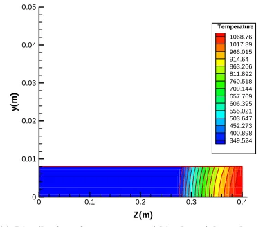
depicted. In h point begins distribution of along the ext of the proces 11 shows dist rough the cyli ely.
a a
mm
R 22 ;
2 1
3
= = =
∞ ∞
r field current area hold:
Hz
50
of work-piec operties of A nd the coil and ng ring move
s
mm
/
5
. Th efore, with theed at a distanc ssumed to be perature.
nder with initial
temperature-nts of cylinder cooling proce
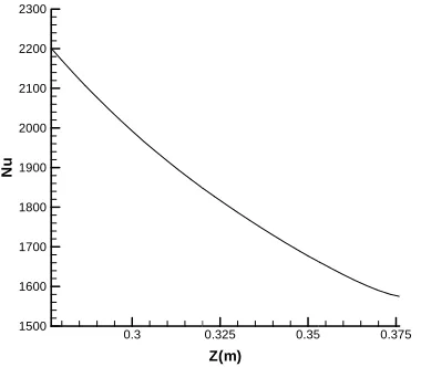
and radiation nt after rea n the other s while the mo f the Local Nu ternal surface ss.
tribution of th inder at the tim
mm mm R
20 26
; 4=
t applied to 4
ce are tempe AISI 4140 st
d their relative along the cyli he width of th
e upper boun ce of
2
cm
be at initial tempposition of coil
time curves r r which are sp ess relevant to is investigate aching at sp words, temp oving spray ap usselt number of cylinder he temperature
me of 100s, 15 m;
4 ×
erature-teel are
e initial inder at he spray ndary of low the perature
relevant pecified o spray ed. The pecified perature pproach r due to at 180s e within 50s and
Fiig. 7, Temperatu
[image:5.595.327.517.329.495.2]Fig. 8 Distribut surf
Fig. 9, Distribu
T
e
m
p
er
a
tu
re(K
)
10 400 500 600 700 800 900 1000 1100
Nu
1500 1600 1700 1800 1900 2000 2100 2200 2300
y(
m
)
0 0 0.01 0.02 0.03 0.04 0.05
ure-time historie
tion Nu due to sp face at 180s after
ution of temperat cylinder at
T
00 200
0.3
0.05
es at six points d
pray cooling alon r beginning of th
ture within the a the time of 100s
Time(s)
300
Z(m)
0.325 0.35
Z(m)
0.1
epicted in previo
ng the cylinder o he process
axial cut through s
400
Point "A Point "B Point "C Point "D Point "E Point "F
5 0.375
0.15
1093.52 1040.49 987.467 934.443 881.418 828.394 775.37 722.345 669.321 616.296 563.272 510.248 457.223 404.199 351.174
Temperature
ous fig.
outer
h the
[image:5.595.322.522.542.713.2]Fig. 10, Distribution of temperature within the axial cut through the cylinder at the time of 150s
Fig. 11, Distribution of temperature within the axial cut through the cylinder at the time of 200s
At the beginning of cooling stage, since the temperature is high, the heat transfer coefficient due to spray cooling is relevant to radiation-dominated region, and gradually with decreasing of temperature the heat transfer coefficient is evaluated by transient region and convection-dominated region equations. Therefore the heat transfer coefficient due to spray cooling increases with passing the time. Consequently, the slope of the temperature-time curve increases with time until the moving spray completely traverses the specified point. Then cooling of cylinder happens only by natural convection with air. And since the heat transfer coefficient of natural convection is so lower than the heat transfer coefficient due to spray cooling, cooling of cylinder occurs at a much lower rate. This process finishes at the moment when the temperature of the any points of cylinder decreases below
C Tfinish =100° .
IV. CONCLUSION
The spray cooling process of vertical hollow circular cylinder which is heated at specified temperature using moving
induction heating is investigated. . Available experimental relations for spray cooling process of steel are used for obtaining forced convection heat transfer coefficient for outer surface due to spray cooling. Solution to this problem described by the coupled Maxwell’s equation (for magnetic analysis) and Fourier’s equation (for thermal analysis) with temperature-dependent properties and time-variable boundary conditions. The effects of natural convection with air and radiation on the both internal and external surfaces of cylinder have been taken into account.
The simulation procedure can be used as a useful tool in induction coil design and in the selection of process parameters. The temperature distribution within work-piece at different times and temperature-time curve for different points are presented and discussed in this paper.
REFERENCES
[1] Woodbury, K. A, The Determination of Surface Heat Fluxes During
Spray Quenching of Aluminum Using an Inverse Technique, ASME Paper No 91. (1991).
[2] F Mueller, H. R., and Jeschar, R., Heat Transfer During Water Spray Cooling of Non-ferrous Metals, Z. Metallkunde, Vol. 74, No. 5 (1983)
pp. 257-264.
[3] Woodbury, K. A., 1991, "The Determination of Surface Heat Fluxes Duringpray Quenching of Aluminum Using an Inverse Technique,''
ASME Paper No.91-WA-HT-12.
[4] Yang, J., Pais, M. R., and Chow, L. C, 1993, "Critical Heat Flux Limits in secondary Gas Atomized Liquid Spray Cooling," Exp. Heat Transfer, No. Vol. 6, 1, pp. 55-67.
[5] P. Buckingham, A. Haji-Sheikh, Cooling of High-Temperature Cylindrical Surfaces Using a Water-Air Spray, Journal of Heat Transfer Transactions of the ASME 117 (1995) 1017-1028.
[6] Thomas, M. Ganesa-Pillai, P.B. Aswatch, K.L. Lawrence and A. Haji- Sheikh, Analytical/Finite-Element Modeling and Experimental, Metallurgical and material transactions A 29A (1998) 1485-1498. [7] Ivo Dolezel, Jerzy Barglik, Bohus Ulrych, Continual induction hardening of axi-symmetric bodies, Journal of Materials Processing Technology 161 (2005) 269–275
[8] K.F. Wang, S. Chandrasekar, and Henry T. Y. Yang, Finite-Element Simulation of Moving Induction Heat Treatment, Journal of Materials Engineering and Performance 4 (1995) 460–473.
[9] Frank P. Incropera, David P. DE Witt, Introduction to Heat Transfer, 4th
Edition John Wiley & Sons, Ltd, New York, 2002.
[10] Bird, R. B„ Stewart, W. E., and Lightfoot, E. N., Transport Phenomena, John Wiley & Sons, Ltd, New York, 1960.
[11] G. E. Totten, C. E. Bates, N. A. Clinton, Hand book of Quenchants and Quenching Technology, ASM International, First printing, 1993. [12] R.W. Lewis, P. Nithiarasu, K.N. Seetharamu, Fundamental of the Finite Element Method for Heat and Fluid Flow, John Wiley & Sons, Ltd, New York, 2004.
[13] M. F. Rothman, High-temperature property Data: Ferrous alloys, ASM International, Metal Park Ohio.
Z(m)
y(
m
)
0 0.1 0.2
0 0.01 0.02 0.03 0.04 0.05
1077.46 1025.51 973.555 921.601 869.647 817.693 765.738 713.784 661.83 609.876 557.921 505.967 454.013 402.059 350.104 Temperature
Z(m)
y(
m
)
0 0.1 0.2 0.3 0.4
0 0.01 0.02 0.03 0.04 0.05
[image:6.595.71.261.314.478.2]