(QJLQHHU
5HFRQQDLVVDQFH
Headquarters,
Department of the Army
By Order of the Secretary of the Army:
DENNIS J. REIMER
General, United States Army
Chief of Staff
Official:
JOEL B. HUDSON
Administrative Assistant to the
Secretary of the Army
DISTRIBUTION:
Active Army, Army National Guard, and US Army Reserve: To be distributed in accordance with
Change 1
Headquarters
Department of the Army
Washington, DC, 1 3 July1998
Engineer Reconnaissance
1.
Change FM 5-170, 5 May 1998, as follows:
Remove Old Pages
Insert New Pages
5-31 through 5-34
5-31 through 5-34
References-1 and References-2
References-1 and References-2
2.
A bar (
I
) marks new or changed material.
3.
File this transmittal sheet in front of the publication.
DISTRIBUTION RESTRICTION: Approved for public release; distribution is unlimited.
By Order of the Secretary of the Army:
DENNIS J. REIMER
General, United States Army
Chief of Staff
Administrative Assistant to the
Secretary of the Army
DISTRIBUTION:
Active Army, USAR, and ARNG: To be distributed in accordance with the initial distribution
Figure 5-26. Sample Ford Reconnaissance Report (back)
recon and pick up divers when the operation is completed. Helicopters may be used to drop teams in the water or place teams on the far shore if the situation permits. Engineer light diving teams routinely conduct river recons at night.
To assist underwater recon teams in maintaining direction, weighted lines (transverse lines) may be placed across the bottom of the water obstacle. Buoys or other floating objects are attached to the lines to indicate the survey area for the underwater recon team(s). When the current is greater than 1.3 meters per second, underwater recon personnel will have difficulty maintaining a position along the line selected. To assist divers, another transverse line, parallel to the original line and with lateral lines connecting both lines, may be placed upstream.
Bottom conditions are easily determined during periods of good visibility and when the water is clear. However, under blackout conditions or when the water is murky, the recon is much slower because swimmers must feel their way across. If the tactical situation permits, diver’s may use underwater lanterns.
Environmental conditions (such as depth, bottom type, tides and currents, visibility, and temperature) have an effect on divers, diving techniques, and equipment. The length of time that divers can remain underwater depends on water depth, time at depth, and equipment used. When conducting a recon in a current, swimmers expend more energy, tire more easily, and use their air supply more quickly. In water temperatures between 73° and 85°F, divers can work comfortably in their swimsuits, but will chill in one to two hours if not exercising. In water temperatures above 85°F, the divers overheat. The maximum water temperature that can be endured, even at rest, is 96°F. At temperatures below 73°F, unprotected divers will be affected by excessive heat loss and become chilled within a short period of time. In cold water, the sense of touch and the ability to work with the hands are affected. Air tanks vary in size and govern how long divers can operate. Extra tanks should be available for underwater recon teams, and the facilities to recharge equipment should be located close enough to respond to team requirements.
Units complete a river-recon report to transmit important information about the river’s loca tio n, n ear- and far- shore ch ar acteri stics, and river characteristics. The information is recorded on DA Form 7398-R as shown in Figures 5-27 and 5-28, pages 5-33 and 5-34.
FERRY RECON
Ferries are considered obstructions to traffic flow and are indicated by the abbreviation “OB” in the route-classification formula. Ferryboat construction varies widely and ranges from expedient rafts to ocean-going vessels. Ferries differ in physical appearance and capacity depending upon the water’s width, depth, and current and the characteristics of the traffic to be moved. Ferries may be propelled by oars; cable and pulleys; poles; the stream current; or steam, gasoline, or diesel engines.
CIVILFERRIES ANDFERRYSITES
Figure 5-28. Sample River Reconnaissance Report (back)
SA
MP
SOURCES USED
These are the sources quoted or paraphrased in this publication.
Army Publications
DA Pam 738-750. Functional Users Manual for the Army Maintenance Management System
(TAMMS). 1 August 1994.
FM 1-114. Tactics, Techniques, and Procedures for the Regimental Aviation Squadron. 20 February 1991.
FM 5-71-2. Armored Task-Force Engineer Combat Operations. 28 June 1996. FM 5-71-3. Brigade Engineer Combat Operations (Armored). 3 October 1995. FM 5-71-100. Division Engineer Combat Operations. 22 April 1993.
FM 5-114. Engineer Operations Short of War. 13 July 1992.
FM 5-250. Explosives and Demolitions. To be published within 6 months. FM 5-446. Military Nonstandard Fixed Bridging. 3 June 1991.
FM 6-20-40. Tactics, Techniques, and Procedures for Fire Support for Brigade Operations (Heavy). 5 January 1990.
FM 6-30. Tactics, Techniques, and Procedures for Observed Fire. 16 July 1991. FM 17-95. Cavalry Operations. 24 December 1996.
FM 17-95-10. The Armored Cavalry Regiment and Squadron. 22 September 1993. FM 17-98. Scout Platoon. 9 September 1994.
FM 20-32. Mine/Countermine Operations. To be published within 6 months. FM 21-26. Map Reading and Land Navigation. 7 May 1993.
FM 34-1. Intelligence and Electronic Warfare Operations. 27 September 1994. FM 34-2. Collection Management and Synchronization Planning. 8 March 1994.
FM 34-2-1. Tactics, Techniques, and Procedures for Reconnaissance and Surveillance and
Intelligence Support to Counterreconnaissance. 19 June 1991.
FM 34-130. Intelligence Preparation of the Battlefield. 8 July 1994.
FM 71-1. Tank and Mechanized Infantry Company Team. 22 November 1988.
FM 71-2. The Tank and Mechanized Infantry Battalion Task Force. 27 September 1988. FM 71-3. The Armored and Mechanized Infantry Brigade. 8 January 1996.
FM 90-13. River Crossing Operations. 30 September 1992.
FM 90-13-1. Combined Arms Breaching Operations. 28 February 1991. FM 100-5. Operations. 14 June 1993.
FM 100-7. Decisive Force: The Army in Theater Operations. 31 May 1995. FM 100-16. Army Operational Support. 31 May 1995.
FM 101-5. Staff Organization and Operations. 31 May 1997. FM 101-5-1. Operational Terms and Graphics. 30 September 1997.
Standardization Agreements
STANAG 2010. Military Load Classification Markings. 18 November 1980.
STANAG 2021. Military Computation of Bridge, Ferry, Raft and Vehicle Classifications. 18 September 1990.
STANAG 2027. Marking of Military Vehicles. 18 December 1975.
STANAG 2253. Roads and Road Structures. 29 January 1982. STANAG 2269. Engineer Resources. 14 May 1979.
DOCUMENTS NEEDED
These documents must be available to the intended users of this publication.
Department of the Army Forms
DA Form 1248. Road Reconnaissance Report. 1 July 1960. DA Form 1249. Bridge Reconnaissance Report. 1 July 1960. DA Form 1250. Tunnel Reconnaissance Report. 1 January 1955. DA Form 1251. Ford Reconnaissance Report. 1 January 1955. DA Form 1252. Ferry Reconnaissance Report. 1 January 1955. DA Form 1711-R. Engineer Reconnaissance Report. May 1985.
DA Form 2028. Recommended Changes to Publications and Blank Forms. 1 February 1974. DA Form 2404. Equipment Inspection and Maintenance Worksheet. 1 April 1979.
DA Form 2408-14. Uncorrected Fault Record. June 1994. DA Form 7398-R. River Reconnaissance Report. June 1998.
READINGS RECOMMENDED
These readings contain relevant supplemental information.
Army Publications
FM 3-4. NBC Protection. 29 May 1992.
FM 3-5. NBC Decontamination. 17 November 1993. FM 3-19. NBC Reconnaissance. 19 November 1993.
Field Manual Headquarters
No. 5-170 Department of the Army
Washington, DC,
ENGINEER RECONNAISSANCE
Table of Contents
Page
Preface... vi Chapter 1. Introduction... 1-1
Organization... 1-1 Missions ... 1-1 Characteristics, Capabilities, and Limitations ... 1-2 General Organizational Characteristics ... 1-2 Engineer Recon Team Capabilities ... 1-2 Engineer Recon Team Limitations ... 1-3 Platform-Specific Capabilities ... 1-4 Command and Support Relationships ... 1-5 Attached ... 1-5 Operational Control (OPCON)... 1-6 Direct Support (DS) and General Support (GS)... 1-6
Chapter 2. Intelligence Preparation of the Battlefield and Reconnaissance and
Surveillance Planning ... 2-1
Intelligence Preparation of the Battlefield (IPB) ... 2-1 R&S Planning... 2-4
Chapter 3. Tactical Reconnaissance ... 3-1
Purpose and Fundamentals... 3-1 Recon Techniques... 3-3 Mounted Recon ... 3-4 Dismounted Recon ... 3-5 Recon by Fire ... 3-5 Indirect Fire ... 3-6 Direct Fire ... 3-6 Aerial Recon ... 3-6 Stealth Versus Aggressive Recon ... 3-7
DISTRIBUTION RESTRICTION: Approved for public release; distribution is unlimited.
____________________________
Route Recon ... 3-7 Critical Tasks ... 3-8 Techniques... 3-8 Example of a Route Recon ... 3-9 Zone Recon ... 3-21 Critical Tasks ... 3-21 Techniques... 3-21 Example of a Zone Recon ... 3-22 Area Recon ... 3-32 Critical Tasks ... 3-32 Techniques... 3-32 Example of an Area Recon... 3-33
Chapter 4. Engineer Recon Team and Obstacle Reconnaissance... 4-1
Personnel and Equipment... 4-1 Training ... 4-1 Equipment ... 4-2 Vehicles ... 4-2 Communications Equipment ... 4-2 Weapon Systems ... 4-2 Additional Equipment ... 4-2 Engineer Recon Team ... 4-2 Dismounted Element ... 4-3 Mounted Element... 4-3 Obstacle and Restriction Recon... 4-3 Detection ... 4-4 Area Security and Recon ... 4-4 Obstacle Recon ... 4-5 COA Selection ... 4-5 COA Recommendation/Execution... 4-7 Examples of Obstacles/Restrictions... 4-7 Employment Concepts... 4-17 Integrated as Part of the Brigade Intelligence-Collection Effort ... 4-17 Assigned Brigade NAIs in a TF’s AO ... 4-18 Working Under a TF’s Control ... 4-18 Support Considerations... 4-19 Responsibilities ... 4-22
Chapter 5. Route Classification ... 5-1
Chapter 6. Combat Support ... 6-1
Indirect-Fire Support ... 6-1 Mortar Support ... 6-1 Capabilities ... 6-2 Limitations... 6-2 Available Munitions ... 6-2 Field Artillery... 6-2 Capabilities ... 6-3 Limitations... 6-3 Available Munitions ... 6-3 Fire-Support Team... 6-4 Fire-Request Channels ... 6-4 Engineer Recon Team Working Under Brigade Control ... 6-4 Engineer Recon Team Working in a TF’s Area or Under TF Control ... 6-6 Engineer Recon Team Working with a Cavalry Squadron or
Under Troop Control ... 6-7 Air Defense... 6-10 Passive Air Defense ... 6-10 Attack Avoidance ... 6-10 Damage-Limiting Measures... 6-10 Active Air Defense... 6-10 Air Support ... 6-11 Ground Surveillance Radar ... 6-12 Capabilities and Limitations ... 6-12 Employment ... 6-13 Chemical ... 6-13 Capabilities and Limitations ... 6-13 Employment ... 6-14
Chapter 7. Combat Service Support ... 7-1
Wounded Soldiers ... 7-9 Soldiers Killed in Action... 7-10 Prisoners ... 7-10 Prisoners of War ... 7-10 Captured Enemy Documents and Equipment ... 7-14 Civilians ... 7-14
Appendix A. Metric Conversion Chart... A-1 Appendix B. Bridge Classification ... B-1
Bridge Signs ... B-1 Width and Height Restrictions... B-2 Classification Procedures ... B-2
Appendix C Sample Reconnaissance OPORD... C-1 Appendix D. Engineer Recon ... D-1 Appendix E. Signs ... E-1
Military Route Signs ... E-1 Hazard Signs... E-2 Regulatory Signs... E-3 Light Line ... E-3 Bridge/Raft Signs ... E-3 Rectangular Bridge Signs ... E-4 Guide Signs ... E-7 Directional Disks... E-7 Headquarters and Logistical Signs ... E-7 Casualty Evacuation Route Signs ... E-8 Unit Direction Arrow ... E-9 Military Detour Signs ... E-9 Road Markers in Areas of Heavy Snow ... E-9 Vehicle Signs ... E-9 Sign Lighting ... E-11
Appendix F. Military Load Classifications ... F-1
Requirement for Classification Numbers ... F-1 Procedures for Vehicle Classification... F-1 Temporary Procedure for Vehicle Classification ... F-1 Expedient Procedure for Wheeled-Vehicle Classification ... F-1 Expedient Procedure for Tracked-Vehicle Classification ... F-2
Field Manual (FM) 5-170 describes how engineer recon teams support and augment a maneuver battalion or brigade’s recon effort. It is designed as an engineer extension of FMs 17-95 and 17-98. This manual serves as a guide for both brigade and task force (TF) engineers, as well as for subordinate leaders (especially recon team leaders) in planning, integrating, and conducting recon operations. It also serves as a guide for the brigade and TF staffs and subordinate maneuver commanders on the organization, capabilities, and employment of engineer recon teams.
This manual sets forth the principles of conducting engineer recon activities supporting a maneuver brigade or TF. It addresses engineer tactics, techniques, and procedures (TTP) that highlight critical principles. However, the TTP are intended to be descriptive rather than prescriptive; they are not a replacement for the TTP and standing operating procedures (SOPs) that are unique to the supported unit.
FM 5-170 is fully compatible with Army doctrine as contained in FM 100-5 and is consistent with other combined-arms doctrine. This is not a stand-alone manual. The user must have a fundamental understanding of the concepts outlined in FMs 100-5, 100-7, 100-16, 71-1, 71-2, 71-3, 17-95, 17-98, 5-71-100, 5-71-2, 5-71-3, 34-1, 34-2, 34-2-1, 34-130, 90-13, 90-13-1, 101-5, and 101-5-1. This manual also implements Standardization Agreement (STANAG) 2269, Engineer Resources, Edition 3; STANAG 2027, Marking of Military Vehicles, Edition 3; STANAG 2253, Roads and Road Structures, Edition 4; STANAG 2174, Military Routes and Route/Road Networks, Edition 4; STANAG 2154, Regulations for Military Motor Vehicle Movement by Road, Edition 6; and STANAG 2010, Military Load Classification Markings, Edition 5.
Appendix A contains an English to metric measurement conversion chart.
The proponent of this publication is Headquarters, United States (US) Army Engineer School (USAES). Send comments and recommendations on Department of the Army (DA) Form 2028 directly to Commander, USAES, ATTN: ATSE-TD-D, Fort Leonard Wood, Missouri, 65473-6650.
Introduction
Combat power is generated by combining the elements of maneuver,
firepower, force protection, and leadership within a sound plan and then
aggressively, violently, and flexibly executing the plan to defeat an enemy.
The key to using combat power effectively is gathering information about
the enemy and the area of operations (AO) through recon. A recon provides
current battlefield information that helps a commander plan and conduct
tactical operations. A recon greatly enhances maneuver, firepower, and
force protection when properly executed.
ORGANIZATION
Engineer recon elements may consist of an engineer platoon, squad, team, or other element. During military operations, the engineer may be called on to assist the maneuver force during recon missions. These missions are normally executed by engineer recon teams, which are organized according to unit SOPs. (See Chapter 4 for a complete discussion of the engineer recon team.) Engineer recon teams may operate independently; however, they normally augment cavalry scout platoons; mechanized, wheeled, or dismounted scout platoons; or other maneuver units directly involved in recon operations. The most prominent scout platoon in a force is the high-mobility, multipurpose wheeled vehicle (HMMWV) scout platoon.
If an engineer recon team is to augment a maneuver scout element, the team should be task-organized with equipment that is compatible with the supported maneuver recon force. The engineer team may use its own vehicle or ride in the vehicles of the scout, cavalry, or infantry unit it supports. It may move mou n ted or di smou nt ed, depen din g on its cu rren t equ ipmen t, organization, command and control (C2) structure, and enemy situation.
MISSIONS
An engineer recon team's primary mission is collecting tactical and technical information for the supported or parent unit. The team must be able to perform this mission mounted or dismounted, during the day or at night, and in various terrain conditions.
A tactical recon is conducted in a high-threat environment and is a combined-arms effort to—
• Collect information about the enemy’s location and obstacles and the terrain within the AO.
• Conduct limited marking of obstacles, routes, and demolition work.
A technical recon is conducted in a low-threat environment. It may or may not be a combined-arms effort to collect engineer-specific technical data on a point or area target or route (see Chapter 5).
CHARACTERISTICS, CAPABILITIES, AND LIMITATIONS
An engineer recon team normally conducts operations as part of a larger combined-arms force. This team has capabilities and limitations that must be considered when they are employed.
GENERAL ORGANIZATIONAL CHARACTERISTICS
Characteristics of a typical recon team include the following:
• The engineer recon team usually depends on both the parent and supported unit for combat support (CS) and combat service support (CSS).
• The scout platoon may perform a recon of two routes simultaneously (for trafficability only) if the engineer recon team is performing a recon with a HMMWV scout platoon.
• The engineer element will assist in reconning a zone 3 to 5 kilometers wide when working with a scout platoon during a zone recon mission. Mission, enemy, terrain , troops, and time available (METT-T) conditions may increase or decrease the zone’s size.
• The engineer recon team must train and rehearse in detail with the unit it supports to ensure that all soldiers understand the recon TTP.
ENGINEER RECON TEAM CAPABILITIES
An engineer recon team has the following capabilities. It—
• Increases the supporting unit’s recon capability concerning complex mine and wire obstacle systems, enemy engineer activities, and details of mobility along a route.
• Provides detailed technical information on any encountered obstacle.
• Conducts an analysis of what assets will be needed to reduce any encountered obstacle.
• Marks bypasses of obstacles based on guidance from the supported commander. This guidance includes whether to mark bypasses and in which direction the force should maneuver when bypassing an obstacle.
• Assists in gathering basic enemy information.
• Provides detailed technical information on routes (including classification) and specific information on any bridges, tunnels, fords, and ferries along the route.
• Assists in acquiring enemy engineer equipment on the battlefield.
ENGINEER RECON TEAM LIMITATIONS
An engineer recon team has the following limitations:
• Engineer battalions do not have personnel and equipment listed on the table(s) of organization and equipment (TOE) and the modified table(s) of organization and equipment (MTOE) dedicated to conduct a recon (see Figures 1-1 through 1-5, pages 1-3 through 1-7).
• The recon team has a limited ability to destroy or repel enemy recon units and security forces.
• The distance the engineer recon team can operate away from the main body is restricted to the range of communications, the range of supporting indirect fires, and the ability to perform CSS operations.
• The recon team has a limited communications capability. Based on the radio configuration of the vehicle used during the recon and whether the engineer recon team is working under a maneuver element’s Figure 1-1. Engineer battalion, engineer brigade, heavy division
Engineer Battalion, Engineer Brigade, Heavy Division* TOE 05335L000
Cbt Engr 5-0-98-103
Support 1-1-56-58
Equipment Recapitulation
30 - HMMWV 12 - Grizzly 1 - Welding trl
28 - APC 6 - M548 1 - Shop equip org
12 - Wolverine 8 - HEMTT cgo 1 - HYSTRU
21 - ACE 4 - HEMTT POL 7 - M577
12 - MICLIC 3 - MTV trk cgo 2 - MKT
12 - 2½-t trl 2 - M88A1E1 (IRV) 6 - Volcano 9 - LMTV trk cgo 3 - HMMWV/maint 6 - SEE 6 - LMTV trl cgo 1 - HEMMT wrecker 2 - ¾-t trl 4 - Water trl 2 - Water drum 18 - 1½-t trl *The engineer battalion, enhanced brigade, has the same TOE.
HHC 11-0-63-74
[image:20.612.131.505.145.534.2]control, dedicated monitoring of engineer nets may be difficult. However, with the single-channel, ground-to-air radio system (SINCGARS), the recon team should be able to scan critical engineer nets or, at the very least, easily switch to the engineer net to report obstacle intelligence (OBSTINTEL).
• The engineer recon team has very limited obstacle creation and reduction ability. It normally carries only a light basic load of demolitions, according to the unit’s SOP. Obstacle reduction is normally limited to manually reducing obstacles not covered by enemy fires and observation.
PLATFORM-SPECIFIC CAPABILITIES
An engineer recon team depends on its organic equipment and the equipment of the unit it supports. Both the engineers and the supported unit must determine the best combination of equipment based on METT-T.
The two engineer vehicles commonly used in recon operations are the M113A3 armored personnel carrier (APC) and the M998 HMMWV. Both vehicles are effective recon platforms when appropriately employed; however, security must come from the supported unit because the vehicles have limited firepower. The engineer must maximize his vehicle’s capabilities and minimize
Figure 1-2. Engineer battalion, light infantry division Engineer Battalion, Light Infantry Division
TOE 05155L000
Equipment Recapitulation
3 - Volcano 3 - MTV trk cgo 1 - Water trl 1 - HMMWV/maint 1 - MTV wrecker 6 - 40-t trl, LB
3 - TUL 2 - MKT 6 - MET
1 - LMTV trl 57 - HMMWV 3 - MTV trl cgo
6 - Deuce 46 - ¾-t trl 18 - SEE
1 - HYSTRU 2 - KCLFF 3 - MTV dump
6 - Water drum 7 - LMTV trk cgo 33-1-376-410
HHC 18-1-124-143
its limitations. A third type of platform is that of a supported maneuver unit when it provides the engineer space on board its vehicle.
COMMAND AND SUPPORT RELATIONSHIPS
Engineers are task-organized a variety of ways, depending on the mission and current requirements. This task organization drives an engineer recon team’s command or support relationship.
ATTACHED
[image:22.612.129.506.84.468.2]When attached, a recon team is temporarily placed in the unit it supports. The commander of the supported unit exercises the same degree of C2 as he does over his organic units. In this relationship, the recon team receives all of its missions and support from the supported unit, not its organic engineer unit. Additionally, the supported-unit commander may task-organize the recon team as he feels is appropriate.
Figure 1-3. Engineer battalion, corps (mechanized) Engineer Battalion, Corps (Mechanized)
TOE 05435L300
HHC 13-1-146-160
Cbt Engr 5-0-100-105 28-1-446-475
Equipment Recapitulation
27 - APC 6 - M548 3 - HEMTT wrecker
33 - HMMWV 6 - Volcano 1 - Welding trl
18 - 1½-t trl 6 - SEE 3 - HMMWV/maint
12 - MICLIC 6 - Bolster trl 13 - HEMTT cgo
12 - 2½-t trl 2 - M577 4 - HEMTT POL
12 - MTV dump trk 2 - MKT 1 - Shop equip org
3 - 11-t flatbed trl 1 - Lube trl 1 - HYSTRU 20 - LMTV trl cgo 3 - Water trl 5 - ¾-t trl
21 - LMTV trk cgo 18 - ACE 1 - Forklift (atlas)
12 - Wolverine 6 - TUL 3 - M88A1E1
OPERATIONAL CONTROL (OPCON)
In an OPCON relationship, a recon team receives all of its tasking and missions from the supported unit. The supported-unit commander retains the same authority over the recon team as over his organic units and may task-organize the recon team as he feels is appropriate. Logistical support comes from the parent engineer unit unless the engineer battalion has coordinated with the supported unit for certain classes of supply.
DIRECT SUPPORT (DS) AND GENERAL SUPPORT (GS)
[image:23.612.111.486.86.423.2]In a DS relationship, a recon team answers directly to the supported unit’s requests for support. Logistical support is provided by the parent engineer un it, an d th e recon team i s comm anded b y its paren t en gin eer u ni t commander. In a GS relationship, a recon team receives missions and all support from its parent engineer unit.
Figure 1-4. Engineer battalion, airborne division Engineer Battalion, Airborne Division
TOE 05025L000
HHC 17-1-130-148
Cbt Engr 5-0-89-94
Equipment Recapitulation
6 - Volcano 1 - Welding trl 2 - Road grader
6 - Deuce 4 - KCLFF 5 - Water trl
2 - MKT 4 - LMTV trl cgo 1 - Lube trl
30 - ¾-t trl 3 - 2½-cy loader 9 - MTV trk dump 1 - HMMWV/maint 6 - MTV trk tractor 6 - 25-t trl, LB
3 - MTV trl cgo 1 - HYSTRU 10 - LMTV trk cgo
27 - SEE 1 - Forklift (atlas) 57 - HMMWV
1 - MTV wrecker 3 - TUL
Figure 1-5. Engineer battalion, air-assault division Engineer Battalion, Air-Assault Division
TOE 05215L000
HHC 17-1-136-154
Cbt Engr 5-0-89-94
Equipment Recapitulation
59 - HMMWV 2 - MKT 12 - T3 dozer
2 - Water trl 1 - 2½-cy loader 1 - LMTV trl cgo
27 - SEE 1 - HMMWV/maint 1 - MTV wrecker
6 - LMTV trk cgo 6 - 25-t trl, LB 1 - TUL
6 - MTV trk dmp 4 - KCLFF 1 - MTV trl cgo
41 - ¾-t trl cgo 1 - HYSTRU 6 - Volcano
Intelligence Preparation of the Battlefield and Reconnaissance and
Surveillance Planning
An engineer recon team performs several critical tasks in support of the
supported-unit commander’s concept of an operation. The recon team’s
success or failure often results in the force’s success or failure. As part of
the commander’s “eyes” and “ears”, the recon team must maintain
co m mu n i ca t io n w it h t h e ta ct i cal o pe ra t io n s c en t e r (T O C ). Th i s
communication link is critical for the recon team to transmit intelligence
gained to the TOC and for the TOC to pass to the recon team any current
information on the friendly and enemy situations.
The engineer recon team leader must clearly understand the commander’s
intent and know what is expected of his team in each phase of the
operation. Also, he must be given the specific named areas of interest
(NAIs) that his team is to observe and the exact information he is expected
to gather within each NAI. The engineer recon team must be focused on
the NAIs that concern obstacles, mobility, or enemy engineer assets.
However, the team should be prepared to report on non-engineer-specific
information as part of the combined-arms recon effort. The team must be
provided with all of the available information concerning the type of
obstacles they may encounter during the recon.
Th e e ng in ee r reco n t ea m mu st be a pa rt of t he suppo rt ed u nit ’s
re co nn a issan ce an d su rve il lan ce (R & S ) plan . Th is e n su res t h at
commanders get the information they need to fight and win the battle. A
maneuver brigade and its subordinate battalions will produce R&S plans.
The brigade plan will task the subordinate battalions, as well as brigade
assets, and these tasks will be incorporated into each subordinate
battalion’s plan.
NOTE: The R&S plan is developed very early in the planning
process because it is critical to get recon assets into a mission as
early as possible.
INTELLIGENCE PREPARATION OF THE BATTLEFIELD (IPB)
Table 2-1 summarizes the engineer’s participation in the IPB process. The Intelligence Officer (US Army) (S2) and the engineer staff conduct their analysis by applying enemy doctrinal templates (which include obstacle templates) to specific terrain. This becomes a situational template (SITEMP). A SITEMP is basically a doctrinal template with terrain and weather constraints applied. It is a graphic description of an enemy’s disposition should he adopt a particular COA. It shows how enemy forces might deviate from doctrinal dispositions, frontages, depths, and echelon spacing to account for the effects of terrain and weather, and it focuses on specific mobility corridors. A SITEMP is a visual technique. By placing a doctrinal template over a segment of a mobility corridor, the analyst adjusts units or equipment dispositions to depict where they might actually be deployed in the situation. Time and space analysis is important in developing a SITEMP, which is used during the war-gaming process. For further discussion of a SITEMP, refer to FM 34-130.
A SITEMP is the basis for event templating. An event template is a model against which enemy activity can be recorded and compared. It represents a sequential projection of events that relate to space and time on the battlefield and indicates the enemy’s ability to adopt a particular COA. By knowing what an enemy can do and comparing it with what he is doing, it can be predicted what he will do next. This is an important analysis factor in determining the enemy’s posture and movement. Knowing when and where enemy activity is likely to occur on the battlefield will provide indicators of enemy intentions or will verify that projected events did or did not occur.
As the threat visualization process develops, a number of critical locations will become apparent (key terrain and man-made features such as bridges and fords). These areas are important because significant events and activities will occur there. It is within these areas that targets will appear. These areas are designated as NAIs. NAIs must be observed to be effective. Therefore, the number and location of NAIs designated is tied to the unit’s ability to observe them.
NAIs may also be developed when the staff produces the decision-support template (DST). The commander and his staff create a DST during the
Table 2-1. Engineer input to the IPB process
Engineer Input IPB Steps Output
Terrain data DEFINE THE BATTLEFIELD
ENVIRONMENT
Available threat engineer assets
Terrain analysis (OCOKA) DESCRIBE THE
BATTLEFIELD’S EFFECTS MCOO
Threat engineer doctrine
EVALUATE THE THREAT Intel estimate
Engineer HVTs
Threat engineer capabilities
Threat engineer support to each
threat COA DETERMINE THREAT COAS
SITEMP
Listing of HVT
Identify NAIs
decision-making process. A DST graphically represents the projected situation, identifying where a decision must be made to initiate a specific activity or event.
NAIs developed during the IPB and decision-making process are prioritized, and recon assets are tasked to collect information to support the commander’s information requirements (IR). Engineer recon teams should be used for those NAIs requiring engineer expertise.
In the offense, a maneuver unit’s S2, with the engineer staff ’s assistance, will determine how and where an enemy will fight, how enemy direct-fire systems and obstacles are arrayed, and what counterattack routes the enemy is likely to take. The assistant brigade engineer (ABE) and the brigade S2 will also provide input on enemy scatterable-mine (SCATMINE) capability and where the mines may be placed, based on how the enemy is predicted to fight. The ABE and the S2 provide any available information about existing obstacles on the avenue of approach or mobility corridor. The TF S2 and the engineer company executive officer (XO)/engineer platoon leader will incorporate this information into their IPB.
In the offen se, an engin eer recon t eam's primary focus sh ou ld be on OBSTINTEL as discussed in FM 90-13-1, Chapter 2. This includes but is not limited to—
• Obstacle location.
• Obstacle orientation.
• The presence of wire.
• Gaps and bypasses.
• Minefield composition (buried or surface antitank [AT] and antipersonnel [AP] mines and antihandling devices [AHDs]) and depth.
• Mine types.
• The location of enemy direct-fire weapons.
In the defense, a maneuver unit’s S2, with the engineer staff ’s assistance, conducts a terrain analysis to determine an enemy’s avenues of approach. The ABE and the brigade S2 work closely with the TF S2 and the engineer company XO/engineer platoon leader in the TF’s TOC to provide input on enemy engineer assets and enemy engineer COAs and to template the enemy’s obstacle use. A recon team may be focused on—
• Obtaining information about planned routes to be used during counterattacks, repositioning, or retrograde operations.
• Augmenting the TF scouts to identify enemy engineer equipment and activity.
• Observing NAIs where the enemy is expected to employ scatterable minefields.
R&S PLANNING
From an event template and a DST, the S2, in coordination with the Operations and Training Officer (US Army) (S3), prepares a detailed R&S plan that graphically depicts where and when the recon elements should look for enemy activity. The R&S plan must direct specific tasks and priorities to all R&S elements: company teams, scout platoons, engineer recon teams, combat observation and lazing teams (COLTs), ground-surveillance radar (GSR), and patrols. The supported battalion’s S2 translates the R&S plan into operational terms and graphics. During recon operations, the S2 designates NAIs for the engineer recon team. The S3 maintains overall OPCON of the R&S plan; however, the S2 plans and monitors the R&S plan. The engineer recon team leader fu rther refin es the plan to in clude such thin gs as checkpoints as control measures to guide the team's movement to these objectives.
The supported unit’s S2 should brief the recon team leader on the disposition of friendly forces and the unit’s scheme of maneuver. The S2 provides the team leader with the current (and projected) R&S and operational graphics and terrain-index-reference-system (TIRS) points to support additional graphics and fragmentary orders (FRAGOs). If the S3 does not brief the recon team leader, the S2 must ensure that the commander's intent is accurately portrayed as he briefs the team leader. The S2 should plan to employ the recon team throughout the mission’s entire course. He should provide guidance on when to report, what actions to take on enemy contact, and what CS and CSS assets are available. The engineer commander must ensure that specifics concerning obstacles, terrain, and enemy engineer assets that may be encountered are also included in this briefing. The recon team leader should receive the S2’s briefing before he departs the battalion area for his mission. Other options, although less desirable, include receiving this information over the radio or from a messenger sent by the commander.
Th e engin eer staff in either the brigade’s or the TF’s TOC sh ould do everything possible to assist the engineer recon team leader by coordinating with other battlefield operating system (BOS) elements. These types of coordination are discussed in the following paragraphs.
A fire-support element (FSE) stays abreast of what the team is doing while conducting the mission. This ensures that it provides responsive fire support to the recon team. The engineer staff should coordinate with the fire-support officer (FSO) to discuss the recon team’s mission and the unique requirements the team has for fire support. The engineer staff finds out what support is available, where supporting units are located, and what fire-support restrictions exist. The team leader then recommends preplanned targets and target priorities that the FSO will incorporate into a recon team’s fire-support plan. The team leader should depart the FSE with an approved target list and/or preplanned fire overlay.
support. A retrans or relay support must be requested if the mission dictates. The engineer recon team should not perform relay duties as their primary mission; however, it is desirable for each vehicle used by the recon team to have the capability to act as a retrans station.
The engineer staff also coordinates with any additional elements that may be providing support to the recon effort (such as air-defense artillery [ADA], COLT, GSR, and aeroscouts). Ideally, any linkups should occur at the TOC during daylight and in sufficient time to conduct a thorough briefing and rehearsal with elements that the recon team is attached to or elements that are attached to the recon team. During a route recon, the engineer recon team must know the number, type (track or wheeled), and load classification of vehicles to be used on the reconned routes. This information will determine route trafficability and help decide COAs during the recon.
The engineer staff coordinates with the appropriate unit Supply Officer (US Army) (S4) (from the engineer battalion, brigade, or TF) to ensure that a feasible CSS plan is in place and that the recon team leader understands where all of his logistical support will come from. Detailed discussion of CSS and recon operations is in Chapter 7.
The engineer recon team leader should, as a minimum, have the following materials on hand and available to his soldiers:
• Operational graphics.
• R&S graphics.
• The SITEMP, event template, and notes on the current enemy situation.
• The fire-support overlay.
• CSS plan (resupply, casualty evacuation, maintenance, and recovery) and CSS graphics.
• Communications plan.
• Compromise procedures.
• Disengagement criteria.
• Linkup plan.
• Contingency plan for NAI coverage.
Once in the vicinity of these recon objectives, the recon team confirms or denies the templated information. The team—
• Looks for engineer-specific information about the obstacle, such as the obstacle’s composition and any bypasses around it.
• Considers limited obstacle reduction.
• Conducts an analysis of the terrain and soil composition to determine w h et h er m i n e-cl ea rin g b l ad es o r m in e -cle ari n g l in e ch arg e s (MICLICs) will be successful.
Tactical Reconnaissance
Engineers are active participants in recon operations that provide both
maneuver and engineer commanders with information about the terrain,
enemy engineer activity, obstacles, and weather effects within an AO. A
tactical recon normally takes place in a high-threat environment. During a
recon, engineers may assist maneuver units or scouts in reconning the
terrain to determine its effect on maneuverability and the enemy
situation. When the enemy is located, the engineers help determine his
strengths and weaknesses with a focus on enemy engineer activities and
obstacles. A recon team provides the information necessary to allow
combined-arms forces to maneuver against the enemy, attack him where
he is most vulnerable, and apply overwhelming firepower to destroy him.
An engineer recon team ensures that the combined-arms forces have the
freedom to maneuver and the knowledge of where they will encounter
enemy obstacles. This chapter provides basic information on recon
operations. Its focus is on providing the engineers the information needed
to allow them to integrate into a maneuver force’s recon effort. Although
this information is most pertinent to tactical recon missions, the methods
discussed should also be used by squads, platoons, and companies when
conducting technical recons.
PURPOSE AND FUNDAMENTALS
A tactical recon is conducted to gain information forward of friendly lines or to provide current, accurate information about terrain, resources, obstacles, and the enemy within a specified AO. This information provides the follow-on forces with an opportunity to maneuver to their objective rapidly. Engineer recon teams are involved in three types of tactical recon: route, zone, and area. During a tactical recon, engineers may also be involved in various technical recons such as road, tunnel, and bridge recons.
There are six fundamentals common to all successful tactical recon operations. Every engineer leader should keep these fundamentals in mind when planning and executing recon missions.
• Using maximum recon force forward. During a recon, every scout, every engineer, and every pair of eyes make a difference. Engineer recon teams must not be kept in the reserve. They must be employed, executing their portion of recon tasks as soon as possible.
feature, a specific area, or an enemy force; it may be designated by an NAI, a checkpoint, or an objective symbol. A recon team must maintain its orientation toward the objective until the mission is complete. The overall objective for an engineer recon team’s mission is l oc a t e d i n t h e s u p p or t e d co m m a n d e r's p ri o ri t y i n t el l i g en ce requirements (PIR), the R&S plan, and/or the commander's intent paragraph in the operations order (OPORD). It is critical that all recon personnel understand the purpose of a recon mission.
• Reporting all information rapidly and accurately. Commanders base their decisions and plans on the battlefield information that scouts, engineers, and other recon assets find and report. Information loses value over time. Scouts and engineers must report all information exactly as they see it and as fast as possible. They must never assume, di st ort , or ex ag g erat e; i n accu rat e i nf orma ti on i s d an g erou s. Information that an enemy or an obstacle is not in a certain location is just as important as where the enemy or obstacle is.
• Retaining freedom of maneuver. All recon elements must be able to maneuver on the battlefield. If a recon element is fixed by the enemy, the element must regain its ability to maneuver or it can no longer accomplish its mission. Recon teams must continually maintain an awareness of tactical developments. They must employ proper m o v e m e n t t e ch n i q u e s a n d r e a c t t o u n e x p e c t e d s i t u a t i o n s appropriately. When contact is made, the recon team leader must develop the situation and retain the initiative and the ability to continue the mission.
• Gaining and maintaining enemy contact. Recon elements employ sound tactical movement, target-acquisition methods, and appropriate actions to make contact with an enemy, undetected, thereby retaining the initiative and control of the situation. Recon elements use the terrain and weather to their advantage to avoid detection. Examples include selecting covered and concealed routes, moving during rain, avoiding roads and danger areas, and selecting unlikely routes to their objectives. Once scouts find the enemy, they maintain contact using all av ailab le mean s (sen sors, radar, sou nd, and vis ual) u ntil t he commander orders them to do otherwise or as required by their specific instructions.
RECON TECHNIQUES
Recon techniques achieve a balance between the acceptable level of risk and the security necessary to ensure mission accomplishment. This balance is often a tradeoff between speed and security. The faster the recon, the more risk a recon team accepts and the less detailed recon it conducts. A recon team must use all available resources when conducting its mission. The primary tools for any engineer recon team are its senses—particularly, sight, hearing, touch, and smell. Recon equipment supplements and complements these senses. The following are some examples of how these senses are used during recon missions:
• Sight. An engineer recon team looks for—
— Evidence of digging activities, including fighting positions and tank ditches.
— Movement or activity of enemy engineer vehicles.
— Indications of buried mines.
— Emplaced demolition charges on bridges, tunnels, and so forth.
— Obstacle orientation, depth, composition, and width.
— Enemy vehicles and aircraft.
— Helicopter landing zones (LZs).
— Sudden or unusual movement.
— Smoke or dust.
— Engine exhaust fumes.
— Unusual movement of farm or wild animals.
— Activity of the local populace.
— Vehicle tracks.
— Signs or evidence of enemy occupation.
— Recently cut foliage or vegetation.
— Lights, fires, or reflections.
— Muzzle flashes.
• Hearing. An engineer recon team listens for—
— Vehicle sounds indicating construction of survivability positions.
— Exploding demolition charges.
— Running engines.
— Track sounds.
— Voices.
— Metallic sounds, especially sounds indicating wire emplacement.
— Unusual calm or silence.
— Dismounted movement through brush or woods.
— Helicopter rotors.
• Touch. An engineer recon team feels for the presence of trip wires or AHDs.
• Smell. An engineer recon team smells for—
— Cooking food.
— Vehicle exhaust.
— Burning petroleum, oils, and lubricants (POL).
— Decaying food or garbage.
To reduce vulnerability on the battlefield, an engineer recon team rehearses recon techniques in detail. The knowledge and rehearsal of recon techniques, c omb in ed w i th a n un de rs t an di ng of a m is si on 's p ar t icu la r ME TT-T requirements, allow the recon team leader to mix and choose the methods that maximize security and mission accomplishment.
This section discusses several recon methods that have proven to be effective in most situations. They form the foundation for tactical recon. Use common sense when analyzing a given situation and employing or modifying the method based on METT-T.
MOUNTED RECON
Maneuver units frequently employ mounted recons. A fairly detailed recon can be conducted while maintaining speed and momentum. Normally, a mounted recon is used when—
• Time is limited.
• Long distances must be traveled.
• A very detailed recon is not required.
• Enemy locations are known.
• Enemy obstacles are known or not expected.
• Enemy contact is not likely.
DISMOUNTED RECON
A dismounted recon’s primary purpose is to obtain detailed information about terrain features, obstacles, or enemy forces. Engineer recon teams normally conduct a dismounted recon. A dismounted recon is conducted when—
• A detailed recon is required.
• Stealth is required.
• Enemy contact is expected or visual contact has been achieved.
• Vehicle movement through an area is restricted by terrain.
• Time is not limited.
• Security is the primary concern.
Recon teams set up short- or long-duration observations posts (OPs). Dismounted personnel must provide security for each other when moving. They should work together in pairs when operating dismounted. When only one person dismounts, he should never move out of supporting distance of the vehicle.
As a minimum, a recon team should carry the following when dismounted:
• SOPs, to include templated information on anticipated obstacles.
• Personal weapons.
• Communications equipment.
• Signal operating instructions (SOI) extracts.
• Maps.
• A compass.
• Binoculars (night-vision devices [NVDs], if necessary).
• Seasonal uniform and load-bearing equipment.
• A global positioning system (GPS).
• Radios.
RECONBY FIRE
In a recon by fire, a recon element places direct/indirect fire on positions where there is a reasonable suspicion of enemy occupation. The goal is to cause an enemy to disclose his presence by moving or returning fire. Recon elements conduct a recon by fire when enemy contact is expected and time is limited or when they cannot maneuver to develop the situation. This method eliminates any element of surprise the scouts may have had, and it is likely to give the enemy detailed knowledge of their location. However, it may reduce the chance of being ambushed within established kill zones. Recon by fire does not work in all cases. For example, disciplined troops in prepared positions will not react to the scout's fires. Examples of situations in which a recon by fire may be employed include—
• The existence of an obvious kill zone.
• A suspected enemy position that fits the SITEMP.
• Signs of recent activity (tracks, marks, or trash).
• Bunker complexes that may or may not be occupied.
When such evidence exists, the scouts should maneuver to observe from different directions. When the decision is finally made to conduct a recon by fire, weapons should be used in the following priority:
• Indirect fire.
• Dismounted machine gun.
• 25-millimeter (mm) chain gun, MK19, and mounted machine gun.
• Tube-launched, optically tracked, wire-guided missile (TOW).
Engineer recon teams do not normally provide a key weapon system during a recon by fire. They are better employed as an observation asset to the firing team.
A recon by fire does not mean indiscriminately using direct and indirect fires at all wood lines and hilltops in the hopes of causing the enemy to react. The enemy will recognize this for what it is; he will not react to it. This also wastes valuable ammunition.
Indirect Fire
Scouts can employ recon by indirect fire (see Figure 3-1). This technique provides them security because they do not disclose their exact position, and they are all available to observe the effects of fire.
A recon by indirect fire has disadvantages as well. Indirect fire requires more coordination and communication than direct fire. Indirect fire is subject to considerations beyond a recon team’s control such as the supporting unit's Class V supply status, counterbattery threats, and command approval. Also, the effects of indirect fire may obscure a scout's vision.
Direct Fire
Scouts can use their organic weapons to place accurate direct fires on suspected enemy positions. This technique is likely to provoke a rapid enemy response, but it reveals the scout's position. Scouts must work together when employing direct fire. A scout who fires is normally not in the best position to observe because of obscuration and the necessity to move to a covered and concealed position after firing. Another scout must observe for an enemy reaction. The recon leader should also plan on placing indirect fires on suspected positions for use as suppression if the enemy responds in strength.
AERIAL RECON
able to access areas that may be difficult or impossible for ground scouts to reach.
The advantage gained by employing air-cavalry assets is multifaceted and flexible enough to accommodate a broad range of ideas and missions. Refer to FMs 1-114 and 17-95-10 for more complete information.
STEALTH VERSUS AGGRESSIVE RECON
The recon team will use either aggressive or stealth recon techniques, based on METT-T. A stealth approach is time-consuming and emphasizes avoiding contact and engaging the enemy. To be effective, a stealth approach must rely on a dismounted recon and maximum use of covered and concealed terrain. An aggressive recon emphasizes the rapid identification of the enemy's combat power and is characterized by a mounted recon and a recon by fire.
ROUTE RECON
Maneuver units or scouts, augmented by engineers, conduct a route recon to gain detailed information about a specific route and the terrain on both sides of the route that the enemy could use to influence movement. When the commander wants to use a specific route, a maneuver unit or scout platoon with an engineer recon team conducts a route recon. This ensures that the route is clear of obstacles and enemy forces and that it will support his vehicles’ movements. Engineers supporting division cavalry squadrons and armored cavalry regiments will routinely support these units in route recon missions.
CRITICAL TASKS
During a route recon, a recon element must accomplish a specified number of tasks unless directed to do otherwise. Based on time available and the commander's intent, the recon element may be directed to conduct a route recon to acquire specific information only. The recon leader must clearly understand which of the following critical tasks must be accomplished:
• Determining the route’s trafficability. (For further information see Chapter 5.)
• Reconning to the limit of direct-fire range and terrain that dominates the route.
• Reconning all built-up areas along the route (includes identifying bypass routes, construction supplies and equipment, ambush sites, evidence of booby traps, and suitable sites for C2/CSS facilities).
• Reconning all lateral routes to the limit of direct-fire range.
• Inspecting and classifying all bridges on the route.
• Locating fords or crossing sites near all bridges on the route (includes determining fordabilty and locating nearby bypasses that can support combat and CSS units, marking bridge classifications and bypass routes, and being prepared to provide guides to the bypasses).
• Inspecting and classifying all overpasses, underpasses, and culverts.
• Reconning all defiles along the route.
• Locating obstacles along the route. (Cavalry units may be required to clear routes of obstacles. See FM 17-95.)
• Locating bypasses around built-up areas, obstacles, and contaminated areas.
• Reporting route information.
• Finding and reporting all enemy forces that can influence movement along the route.
TECHNIQUES
Because of the number of critical tasks that must be accomplished, a scout platoon with an engineer recon team can conduct a detailed recon of only one route. A scout platoon may be able to handle two routes if the recon is limited to trafficability only. The following discussion outlines one technique of accomplishing all tasks as rapidly and securely as possible.
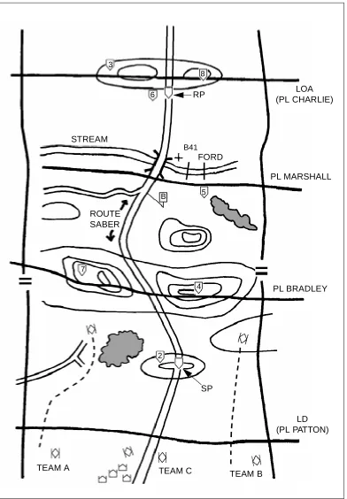
scouts recon all terrain that the enemy could use to influence movement along the route. An LD is drawn from one boundary to the other behind the SP. This allows the platoon to cross the LD and be fully deployed before reaching the route. An LOA or objective is placed beyond the RP on the last terrain feature dominating the route or out to about 3 kilometers (see Figure 3-2, page 3-10).
The recon platoon leader may add additional PLs, contact points, and checkpoints to the graphics he receives from his commander. PLs are used to help control the platoon’s maneuver. The contact points ensure that the teams maintain contact at particular critical points. Checkpoints are used along a route or on specific terrain to control movement or to designate areas that must be reconned. The engineer recon team leader should obtain this information during the scout platoon OPORD briefing.
The recon platoon leader will also coordinate with the FSO and plan artillery targets on known or suspected enemy positions and on dominant terrain throughout the AO. The engineer recon team leader must ensure that this information is included on his overlay.
The recon platoon leader evaluates the METT-T factors and organizes his platoon with an engineer recon team to meet mission needs. He ensures that at least one team is respon sible for recon ning a route. A th ree-team organization is usually the type best suited to recon a route. Team A recons the terrain left of the route, Team B covers the terrain right of the route, and Team C and the engineer recon team recon the route and controls the movement of the other two teams. In this organization, the platoon leader's team has specific responsibility to clear the route (see Figure 3-3, page 3-11). The engineer recon team’s tasks will likely include a technical recon of the route (including bridge load classification and possible locations for employing SCATMINEs).
EXAMPLEOFA ROUTE RECON
The following example of a route recon is for a cavalry scout platoon with an engineer platoon attached.
Figure 3-2. Control measures
LOA (PL CHARLIE)
PL MARSHALL
PL BRADLEY
LD (PL PATTON) STREAM
ROUTE SABER
RP
SP
3
8
5 6
B41
7
4
Figure 3-3. Conducting a route recon
PL MARSHALL
PL BRADLEY
LD (PL PATTON) STREAM
RP
SP
3
8
5 6
B41
7
4
2
LOA (PL CHARLIE)
Figure 3-4. Route recon
LOA (PL CHARLIE)
PL MARSHALL
PL BRADLEY
LD (PL PATTON) STREAM
ROUTE SABER
RP
SP
3
8
5 6
B41
7
4
2 B
FORD
TEAM A
TEAM C
The scout platoon leader is responsible for movement through the zone. He uses checkpoints to control the movement and to focus on obstacles, key terrain, or features that may influence movement along the route. The engineers focus on obstacles that must be located and cleared. Their efforts must focus on specific PIR to ensure that the recon occurs in a timely manner.
Team C should be positioned along the route so that it can observe the route, and one element of the team must physically drive the entire route. Unless the sector is very small or very open, the platoon will move as individual teams. As the sections move to the checkpoints, they maneuver in a zigzag pattern to clear the sector and accomplish all critical tasks of a route recon. The lead teams on the flanks must observe the route and report any restrictions or obstacles that may restrict movement along the route. Visually clearing the route before Team C travels along it provides for better security and allows Team C to concentrate on the critical recon tasks. As the teams maneuver toward the checkpoints, they maintain visual contact with the route (see Figure 3-5, page 3-14).
After both lead teams report "Set" and are in overwatch positions, Team C begins the route recon (see Figure 3-6, page 3-15). As the platoon leader moves along the route, his wingman maneuvers to provide overwatch for the platoon leader and the engineer platoon. As the engineer platoon leader travels along Route Saber, he is normally required to send a route classification of the trafficability at intervals designated by the commander. A route report may be required only if there is a significant or unexpected change in the route's makeup.
As Team C clears the route, the other teams move ahead, clearing and reconning critical and dominant terrain. The platoon leader controls and coordinates the teams’ movements. He must ensure that the flank teams remain far enough forward of Team C to provide security. The flank teams are also assigned responsibility for covering lateral routes. Team A executes a lateral route and uses contact point B to tie with Team C on Route Saber (see Figure 3-7, page 3-16).
The platoon order must address actions on the approach to the stream. In this case, the two flank teams have been given the task of locating bypasses in the form of fords or unmapped bridges. Team B is successful in locating a ford; Team A is not. The engineer platoon sends one squad to checkpoint 5, links up with Team B, and conducts a ford recon. Team B focuses on the steps used for obstacle and restriction recon and continues its mission (see Figure 3-8, page 3-17).
The engineer squad moves back to contact point B and links up with Team C and the rest of the engineer platoon. Team C continues its route recon along the route until it approaches the bridge site. It then executes a bridge recon to establish the bridge’s trafficability. Team A occupies an overwatch position while Team C and the engineer platoon recon the bridge. Team B continues its recon one terrain feature beyond the stream and then occupies a short-duration OP (see Figure 3-9, page 3-18).
Figure 3-5. Route recon (continued)
LOA (PL CHARLIE)
PL MARSHALL
PL BRADLEY
LD (PL PATTON) STREAM
ROUTE SABER
RP
SP
3
8
5 6
7
4
2 B
FORD
TEAM A TEAM C
TEAM B
Figure 3-6. Team C begins route recon
LOA (PL CHARLIE)
PL MARSHALL
PL BRADLEY
LD (PL PATTON) STREAM
ROUTE SABER
RP
SP
3
8
5 6
7
4
2 B
FORD
TEAM A
TEAM C
TEAM B
Figure 3-7. Team A executes lateral route
LOA (PL CHARLIE)
PL MARSHALL
PL BRADLEY
LD (PL PATTON) STREAM
ROUTE SABER
RP
SP
3
8
5 6
7
4
2 B
FORD
B41
TEAM A
TEAM B
Figure 3-8. Team B (with engineers) conducts ford recon
LOA (PL CHARLIE)
PL MARSHALL
PL BRADLEY
LD (PL PATTON) STREAM
ROUTE SABER
RP
SP
3
8
5 6
7
4
2 B
B41
TEAM B TEAM C
Figure 3-9. Team C (with engineers) conducts bridge recon
LOA (PL CHARLIE)
PL MARSHALL
PL BRADLEY
LD (PL PATTON) STREAM
ROUTE SABER
RP
SP
3
8
5 6
7
4
2 B
B41
TEAM C TEAM A
Figure 3-10. Team A crosses the bridge
LOA (PL CHARLIE)
PL MARSHALL
PL BRADLEY
LD (PL PATTON) STREAM
ROUTE SABER
RP
SP
3
8
5 6
7
4
2 B
B41
TEAM C
Figure 3-11. Team C moves to recon LOA
LOA (PL CHARLIE)
PL MARSHALL
PL BRADLEY
LD (PL PATTON) STREAM
ROUTE SABER
SP
3
8
5 6
7
4
2 B
B41
TEAM C TEAM A
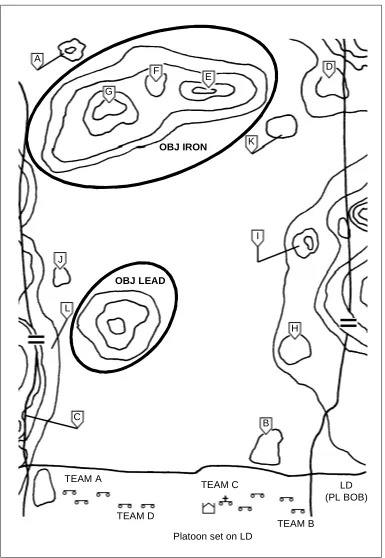
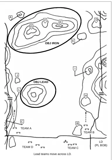
ZONE RECON
Maneuver units and scouts, with the assistance of engineers, conduct zone recon missions to gain detailed information about routes, terrain, resources, and enemy forces within a zone defined by lateral boundaries. Commanders normally assign a zone recon mission when they need information before sending their main-body forces through the zone. The recon produces information about the enemy situation and about routes and cross-country trafficability within the zone. Engineers play a primary role in obtaining route and cross-country trafficability information. This is the most thorough and complete recon mission; therefore, it is very time intensive. It is common for scouts executing a zone recon with engineer assistance to advance at only 1.5 kilometers per hour.
CRITICAL TASKS
During a zone recon, a recon element must accomplish a specified number of tasks unless directed to do otherwise. Th e recon leader mu st clearly understand which of the following critical tasks must be accomplished:
• Reconning key terrain in the zone.
• Inspecting and classifying all key bridges within the zone.
• Locating suitable fording or crossing sites near all bridges within the zone.
• Inspecting and classifying all overpasses, underpasses, and culverts.
• Locating obstacles in the zone; determining how to reduce obstacles (assets and time) when needed. (Cavalry units may be required to clear the zone of obstacles. See FM 17-95.)
• Locating bypasses around built-up areas, obstacles, and contaminated areas.
• Reporting enemy forces in the zone.
• Reporting recon information.
TECHNIQUES
A zone recon is a very time-consuming operation. Unless the orders specify otherwise, all critical tasks listed above are implied in the zone recon mission statement. Commanders who want a faster tempo of operations need to modify the mission statement and ensure that the recon element knows what its primary recon tasks are. For example, the TF commander may have critical bridges that need classification to ensure that the main body can move with freedom. However, he may have two other bridges within the zone that will not be used by the TF and do not need to be classified.
When a recon leader receives a zone recon mission, the order will define the zone by lateral boundaries, an LD, and an LOA or objective. The parent unit may include additional PLs or other graphic control measures within the zone to help control the maneuver of the units.
Th e re con l e ad er an al y z es t h e m is s i on to d et erm i n e w h at mu s t b e accomplished. He analyzes any information about the enemy during the IPB to determine what enemy activity he should expect to encounter. The engineer commander should work with the recon leader, the S2, and the S3 to ensure that engineer recon tasks are identified and that enough engineers are attached to the recon element to accomplish the mission. The engineer commander will help analyze the terrain by—
• Assisting the S2 in map recon.
• Examining aerial photographs.
• Using an automated terrain-visualization tool.
Depending on the type of recon element, the experience of the attached engineer recon team, and METT-T considerations, the element can conduct the zone recon using a two-, three-, or four-team organization. The recon element must deploy to cover the entire zone. It usually operates in a zone it knows very little about, so the COA must allow for flexibility, responsiveness, and security as it moves. The recon leader deploys the scout teams on line across the LD. He uses PLs, checkpoints, contact points, or TIRS points to ensure that the element recons the entire zone and that teams maintain contact with each other. He ensures that scout teams remain generally on line, which prevents significant gaps that a moving enemy could exploit. Scouts and engineers dismount as necessary to gather detailed information, clear danger areas, or move through areas that are not accessible to the vehicles. The element continues to recon the zone until it reaches the LOA or the final recon objective.
EXAMPLEOFA ZONE RECON
The following example of a zone recon is for a battalion scout platoon augmented with an engineer recon team.
Figure 3-12. Scouts and engineers cross the LD
G
H
4
LOA (PL RUN)
PL SALLY
PL DICK
LD (PL SPOT) 3
C
D
E
B
F
J
2
I 1
STREAM
A A
B C
C
FORD
Figure 3-13. Zone recon
G
H
4
LOA (PL RUN)
PL SALLY
PL DICK
LD (PL SPOT) 3
C
D
E
B
F
J
2
I 1
STREAM
A A
B C
C
FORD
Depending on METT-T factors, the platoon leader chooses the movement technique best suited for C2. He may choose to have the teams clear and set at all checkpoints, or he may have them bound through the checkpoints, report clear, and then set at the PLs. If the platoon leader has not assigned teams a particular checkpoint to orient on, the team leaders must plan their own measures to control the movement. They move team elements to contact points to ensure that the move is tied in with that of the other teams. The platoon leader does not allow any element to cross PL Dick until all elements have reported set (see Figure 3-14, page 3-26).
When the platoon is set on PL Dick, the leader gives the teams permission to execute PL Dick and move to PL Sally. The teams immediately begin reconning the stream to their front. Team A and the engineer recon team must execute a bridge recon and recon the stream for possible unmarked fords. They must conduct a ford recon at the known ford in zone.
Once Team C completes its recon of the stream and reports negative results, it moves to the vicinity of contact point 2 and awaits permission to cross the stream at Team B's ford. Team C is also prepared to cross at Team A's bridge, if necessary (see Figure 3-15, page 3-27).
As Team A (with an engineer recon team) and Team B complete their recon tasks at the bridge and ford, they revert to the bounding-overwatch movement technique and continue to recon. Team C moves across the team boundary and prepares to cross the stream at the ford (see Figure 3-16, page 3-28).
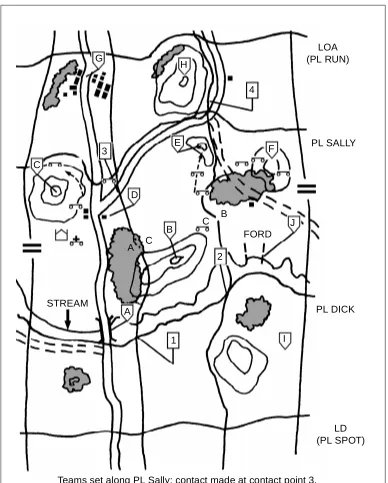
The zone recon continues with Teams A and B clearing checkpoints D and F, respectively. The platoon leader holds the teams at those control measures to allow time for Team C to clear checkpoint B and get on line with the other teams at checkpoint E. This prevents dangerous gaps from developing between the teams (see Figure 3-17, page 3-29).
Once Team C sets at checkpoint E, the platoon leader has all elements on line and set along PL Sally. Teams A and C ensure that they make contact at contact point 3. The platoon leader gives permission for all elements to execute PL Sally and move to and set at PL Run (see Figure 3-18, page 3-30).
Figure 3-14. Teams set at PL Dick
G
H
4
LOA (PL RUN)
PL SALLY
PL DICK
LD (PL SPOT) 3
C
D
E
B
F
J
2
I 1
STREAM
A A
B C
C
FORD
Figure 3-15. Team C completes recon
G
H
4
LOA (PL RUN)
PL SALLY
PL DICK
LD (PL SPOT) 3
C
D
E
B
F
J
2
I 1
STREAM
A A
B C
C FORD
Figure 3-16. Teams A and B complete recon
G
H
4
LOA (PL RUN)
PL SALLY
PL DICK
LD (PL SPOT) 3
C
D
E
B
F
J
2
I 1
STREAM
A A
B C
C
FORD
Figure 3-17. Teams A and B are halted
G
H
4