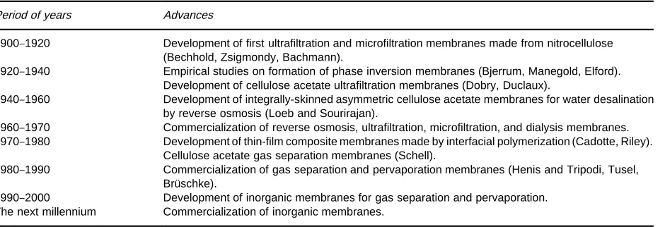
Table 1 Major milestones in the development of membranes for industrial separations
Period of years Advances
1900}1920 Development of first ultrafiltration and microfiltration membranes made from nitrocellulose (Bechhold, Zsigmondy, Bachmann).
1920}1940 Empirical studies on formation of phase inversion membranes (Bjerrum, Manegold, Elford). Development of cellulose acetate ultrafiltration membranes (Dobry, Duclaux).
1940}1960 Development of integrally-skinned asymmetric cellulose acetate membranes for water desalination by reverse osmosis (Loeb and Sourirajan).
1960}1970 Commercialization of reverse osmosis, ultrafiltration, microfiltration, and dialysis membranes. 1970}1980 Development of thin-film composite membranes made by interfacial polymerization (Cadotte, Riley).
Cellulose acetate gas separation membranes (Schell).
1980}1990 Commercialization of gas separation and pervaporation membranes (Henis and Tripodi, Tusel, BruKschke).
1990}2000 Development of inorganic membranes for gas separation and pervaporation. The next millennium Commercialization of inorganic membranes.
should lead to continued development of membrane systems for bioseparations.
See also: II / Membrane Separations: Microfiltration; Ultrafiltration.
Further Reading
Belfort G, Davis RH and Zydney AL (1994) The behavior of suspensions and macromolecular solutions in cross-Sow microRltration.Journal of Membrane Science96: 1. Blatt WF, Dravid A, Michaels AS and Nelsen L (1970) Solute polarization and cake formation in membrane ultraRltration. Causes, consequences, and control tech-niques. In: Flinn JE (ed.)Membrane Science and Techno-logy, pp. 47}97. New York: Plenum Press.
Cheryan M (1997) UltraTltration and MicroTltration Handbook. Lancaster, PA: Technomic.
Ferry JD (1936) UltraRlter membranes and ultraRltration. Chemical Reviews18: 373.
Ho WSW and Sirkar KK (eds) (1992)Membrane Hand-book. New York: Chapman&Hall.
Lonsdale HK (1982) The growth of membrane technology. Journal of Membrane Science10: 81.
McGregor WC (ed.) (1986) Membrane Separations in Biotechnology. New York: Marcel Dekker.
van Reis R and Zydney AL (1999) Protein ultraRltration. In: Flickinger MC and Drew SW (eds)Encyclopedia of Bioprocess Technology:Fermentation,Biocatalysis,and Bioseparation, pp. 2197}2214. New York: John Wiley. Zeman LJ and Zydney AL (1996) MicroTltration and UltraTltration:Principles and Applications. New York: Marcel Dekker.
Membrane Preparation
I. Pinnau, Membrane Technology and Research,
Inc., Menlo Park, CA, USA
Copyright^ 2000 Academic Press
Background
A membrane (Latin,membrana, skin) is a thin barrier that permits selective mass transport. Between 1850 and 1900, membranes were used to derive basic phys-ical principles for gas and liquid transport across a barrier material (see the work of Mitchell, Fick and Graham). In these early studies it was already recog-nized that membranes could be used to separateSuid mixtures. Membranes used at that time included denseRlms of nitrocellulose, natural rubber, and pal-ladium. The Rrst commercial synthetic membranes
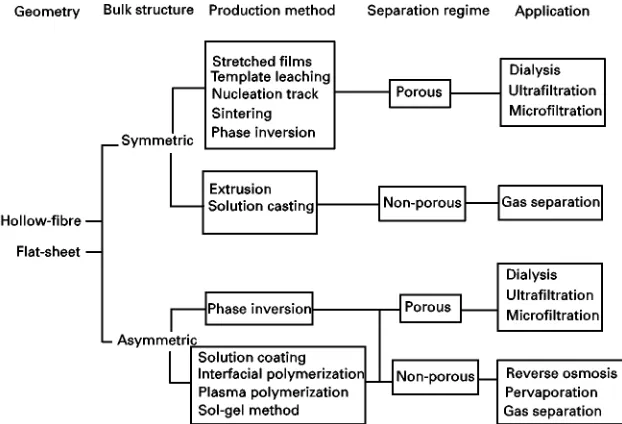
Further-Figure 1 Classification scheme of synthetic membranes based on their geometry, bulk structure, production method, separation regime, and application.
more, methods of efRciently packaging membranes into modules (plate-and-frame, spiral-wound, and hollow-Rbre) were developed during this period. Around 1980, the use of membranes for separations was established as a unit operation process in the chemical process industry. Further optimization of membrane preparation and modiRcation methods from 1980 to 1990 made membrane separations competitive in gas separation and liquid separation applications. The most important production methods that resulted in the commercial use of syn-thetic membranes are listed inTable 1. Recent atten-tion has been directed towards the development of inorganic membranes. Optimized inorganic mem-branes can have signiRcantly better separation properties compared to state-of-the-art polymeric membranes. However, currently the main limitations for large-scale commercialization of inorganic mem-branes are their poor mechanical strength (brittle-ness) and extremely high manufacturing costs.
Membrane Types
Membranes can be distinguished based on their (i) geometry, (ii) bulk structure, (iii) production method, (iv) separation regime, and (v) application, as shown in Figure 1. Most commonly, membranes are pro-duced in Sat-sheet or tubular (hollow-Rbre) ge-ometry. Flat-sheet membranes are either packaged in plate-and-frame or spiral-wound modules, whereas tubular membranes are packaged in hollow-Rbre modules. The choice of the optimum membrane and module type depends on a wide variety of process
speciRc conditions. Although hollow-Rbre modules offer the highest membrane area per module volume ratio, plate-and-frame and spiral-wound modules are also commonly used for large-scale separations be-cause of their better control ofSuid dynamics.
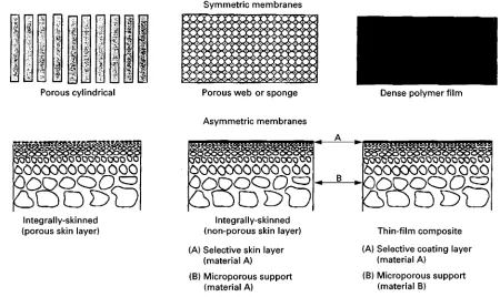
Membranes either have a symmetric (isotropic) or an asymmetric (anisotropic) structure. The structure of a symmetric membrane is uniform throughout its entire thickness, whereas asymmetric membranes have a gradient in structure. The Sux of a Suid through a symmetric membrane is typically relatively low, as the entire membrane thickness contributes a resistance to mass transport. Asymmetric mem-branes consist of two structural elements, that is, a thin, selective layer and a microporous substruc-ture. Typically, the bulk structure (99#%) of an asymmetric membrane is highly porous and provides only mechanical strength. Separation of aSuid mix-ture in an asymmetric membrane is performed in a very thin surface layer, which is typically of the order of 0.1}0.5m thick. The most common sym-metric and asymsym-metric membrane types are shown in Figure 2.
Ideal Membranes for Separations
[image:2.568.129.440.470.682.2]Figure 2 Schematic representation of symmetric and asymmetric membrane structures.
membrane must exhibit at least the following charac-teristics: (i) highSux, (ii) high selectivity (rejection), (iii) mechanical stability, (iv) tolerance to all feed stream components (fouling resistance), (v) tolerance to temperature variations, (vi) manufacturing repro-ducibility, (vii) low manufacturing cost, and (viii) ability to be packaged into high surface area modules. Of the above requirements,Sux and selectivity (rejec-tion) determine the selective mass transport proper-ties of a membrane. The higher the Sux of a brane at a given driving force, the lower is the mem-brane area required for a given feed Sow rate, and, therefore, the lower are the capital costs of a mem-brane system. The selectivity determines the extent of separation, and, therefore, the purity of the desired product.
Typically, porous membranes are used in dialysis, ultraRltration, and microRltration applications. Ideal porous membranes have high porosity and a narrow pore size distribution. Membranes having a dense, selective layer are applied in reverse osmosis, per-vaporation, and gas separation processes. Permeation through dense membranes occurs by a solution/ diffu-sion mechanism. Ideal dense membranes should have a very thin selective layer, because Sux is inversely proportional to the membrane thickness. In addition, the thin separating layer must be pinhole-free, because even a very small area fraction of defects in the mem-brane can cause a signiRcant decrease in selectivity.
Polymeric Membranes
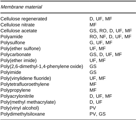
Currently, most commercial membranes are made from polymers. Polymeric membranes can be fab-ricated by a wide variety of methods and fulRll most of the requirements of an ideal membrane listed above. Membranes are made from amorphous as well as semi-crystalline polymers by solution- or melt-processes. A list of commonly used polymers for com-merical membrane separation processes is given in Table 2.
Symmetric Membranes
Dense Symmetric Membranes
Dense symmetric membranes with thicknesses greater than 10m can be made by melt extrusion or solution casting and subsequent solvent evaporation. Because theSuxes of Suids through dense polymer Rlms are very low, this membrane type is rarely used for large-scale separations. Dense symmetric, ion-exchange membranes are used in electrodialysis applications for production of potable water from brackish water.
Porous Symmetric Membranes
Table 2 Polymers used for production of commercial mem-branes
Membrane material
Cellulose regenerated D, UF, MF
Cellulose nitrate MF
Cellulose acetate GS, RO, D, UF, MF
Polyamide RO, NF, D, UF, MF
Polysulfone G, UF, MF
Poly(ether sulfone) UF, MF
Polycarbonate GS, D, UF, MF
Poly(ether imide) UF, MF
Poly(2,6-dimethyl-1,4-phenylene oxide) GS
Polyimide GS
Poly(vinylidene fluoride) UF, MF
Polytetrafluoroethylene MF
Polypropylene MF
Polyacrylonitrile D, UF, MF
Poly(methyl methacrylate) D, UF
Poly(vinyl alcohol) PV
Polydimethylsiloxane PV, GS
MF"microfiltration; UF"ultrafiltration; NF"nanofiltration; D"dialysis; PV"pervaporation; GS"gas separation.
important methods for the production of symmetric porous membranes are: (i) irradiation, (ii) stretching of a melt-processed semi-crystalline polymer Rlm, (iii) template leaching, (iv) temperature-induced phase separation, and (v) vapour-induced phase separation.
Symmetric membranes with a cylindrical pore structure can be produced by an irradiation-etching process. These membranes are often referred to as nucleation track membranes. In theRrst step of this process, a dense polymerRlm, such as polycarbonate or polyester, is irradiated with charged particles, which cause chain scission and leave behind a sensi-tized track of damaged polymer molecules. These tracks are more susceptible to attack by chemical agents than the undamaged, base polymerRlm. In the second step, the Rlm is passed through an etching medium, typically a sodium hydroxide solution. Dur-ing this process, pores are formed by etchDur-ing the partially degraded polymer along the nucleation tracks. Membranes made by this method have a very uniform pore size. The porosity and pore size of nucleation track membranes can be controlled by the irradiation time and etching time, respectively.
Membranes with a symmetric slit-like pore struc-ture can be made from semi-crystalline polymers, such as polyethylene, polypropylene or polytetra-Suoroethylene, using a melt extrusion/stretching pro-cess. In theRrst process step, a highly orientedRlm is formed by melt-extrusion of a semi-crystalline poly-mer and re-crystallization under high stress. The crys-tallites in the semi-crystalline polymerRlm are then
aligned in the direction of orientation. In the second step, slit-like pores, about 200}2500 A> wide, are for-med between the stacked lamellae by stretching the membrane in the machine direction. The pore size of these membranes is determined by the rate and extent of stretching during the second process step. Com-mercial membranes made by the extrusion/stretching process are available from Hoechst}Celanese (Cel-gard威) and W.L. Gore (Gore-Tex威).
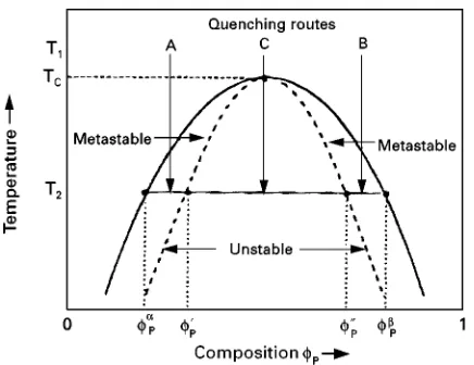
Figure 3 Schematic diagram of a binary polymer-solvent sys-tem with an upper critical solution sys-temperature (UCST).
fraction of solvent-rich phase dispersed in a large volume fraction of polymer-rich phase. The resulting morphology is a sponge- or foam-like porous struc-ture. A thermal quench of solution C passes directly into the unstable region of the phase diagram; there-fore, phase separation occurs by spinodal decomposi-tion. Typically, phase separation by spinodal de-composition leads to an interconnected, porous struc-ture. TheRnal membrane structure depends not only on liquid}liquid phase separation phenomena but also on the kinetics of the thermal quench process and the distribution of the polymer-rich phase at the point of solidiRcation. Typically, a rapid quench rate results in a large fraction of small pores, whereas a slow quench rate produces fewer, but larger pores.
Symmetric membranes with sponge- or web-like pore structures can also be made by a vapour-precipi-tation/evaporation technique. Membranes made by this method are highly porous and are typically used in microRltration applications. In its simplest form of the method, a solution containing polymer, solvents and non-solvents is cast onto a substrate and is then exposed to a water-vapour-saturated air stream. The water vapour induces phase separation in the initially stable polymer solution. After phase separation, the solvent and non-solvent components are evaporated by blowing a hot air stream across the membrane. The porosity and pore size of this membrane type can be controlled by: (i) the polymer concentration in the casting solution and (ii) the composition of the vapour atmosphere. Low polymer concentration, high humidity, and the addition of solvent-vapour to the casting atmosphere lead to membranes with high porosity and large pore size. Because mem-branes made by the vapour-precipitation/evaporation method have an essentially constant polymer concen-tration proRle throughout the entire membrane
thick-ness at the onset of phase separation, the resulting membranes are porous and have a fairly symmetric structure.
Asymmetric Membranes
The most commonly used asymmetric membranes are: (i) integral-asymmetric with a porous skin layer, (ii) integral-asymmetric with a dense skin layer, and (iii) thin-Rlm composite membranes. Integrally-skin-ned asymmetric membranes are typically made by a non-solvent induced phase separation process (im-mersion precipitation) and consist of a thin, selective layer and a porous substructure. Both skin layer and substructure are formed simultaneously during the immersion precipitation process. Porous integral-asymmetric membranes are applied in dialysis, ultra-Rltration, and microRltration applications, whereas integral-asymmetric membranes with a dense skin layer are used in reverse osmosis and gas separation applications. Thin-Rlm composite membranes consist of a thin, selective polymer layer atop a porous sup-port. In this membrane type, the separation and mechanical functions are assigned to different layers in the membrane. This membrane type was originally developed for reverse osmosis applications; however, nowadays thin-Rlm composite membranes are also used in nanoRltration, gas separation, and pervapora-tion applicapervapora-tions.
Integrally-Skinned Asymmetric Membranes
The Rrst integrally-skinned asymmetric membranes were developed by Loeb and Sourirajan in the early 1960s for seawater desalination by reverse osmosis. In the original Loeb}Sourirajan technique, thin-skin-ned (&0.2m) cellulose acetate membranes were made by a four-step process: (i) casting of a multi-component polymer solution, (ii) partial evaporation of a volatile solvent, (iii) immersion of the nascent polymer Rlm into a non-solvent (water), and (iv) thermal annealing of the water-wet membrane. Mem-branes made by this method had waterSuxes orders of magnitude higher than those of thick, isotropic cellulose acetateRlms while maintaining high sodium chloride rejection ('90%). The Loeb}Sourirajan method has been modiRed and applied to a wide variety of polymers other than cellulose acetate. In fact, the Loeb}Sourirajan process is by far the most important method for production of commercial membranes for separations.
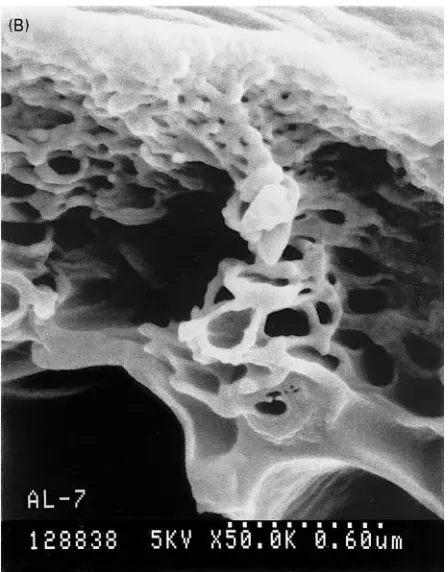
Figure 4 (A) Porous bulk structure and (B) skin layer of an integrally-skinned asymmetric polysulfone membrane made by the immersion precipitation process.
a non-solvent for the polymer but miscible with the solvent, an asymmetric structure with either a porous or non-porous skin layer is formed. The structural gradient in an integrally-skinned asymmetric mem-brane results from a very steep polymer concentration
gradient in the nascent membrane at the onset of phase separation. The structure of a typical mem-brane made by immersion precipitation having a highly porous substructure and a thin skin layer is shown in Figure 4(A) and 4(B). In the immersion precipitation process, phase separation can be in-duced by: (i) solvent evaporation and/or (ii) sol-vent/non-solvent exchange during the quench step. Typically, the formation of membranes made by the immersion precipitation method occurs over a very short time scale, typically less than a few seconds. Most commercial membranes made by the immersion precipitation method are made from multi-compon-ent solutions containing polymer, solvmulti-compon-ent(s), and non-solvent(s) or additives. The porosity, pore size, and skin layer thickness can be modiRed by the addi-tion of non-solvents to the casting soluaddi-tion (e.g. alco-hols, carboxylic acids, surfactants, etc.), inorganic salts (e.g. LiNO3 or ZnCl2, etc.) or polymers (e.g. polyvinylpyrrolidone, polyethylene glycol, etc.). Even very small amounts of these solution additives can have a signiRcant effect on the membrane structure, and hence, its separation properties. The structure of membranes made by immersion precipitation can also be altered by using multi-component quench media. For example, the addition of a solvent to the quench medium results in an increase in the surface porosity and pore size of the membrane. The formation of membranes made by the immersion pre-cipitation process depends on a large number of material- and process-speciRc parameters including:
E choice of the polymer (molecular weight, molecu-lar weight distribution)
E choice of the solvent(s) and additives E composition of the casting solution E choice of the quench medium
E composition and temperature of the casting atmo-sphere
E temperature of the casting solution and quench medium
E evaporation conditions E casting thickness
E casting or spinning speed
E membrane support material (type of woven or non-woven)
E drying conditions.
Thin-Film Composite Membranes
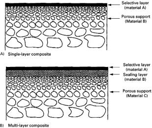
Figure 5 Schematic diagram of (A) single-layer and (B) multi-layer thin-film composite membranes.
performed by the thin top-layer. A multi-layer com-posite membrane (5B) consists of a porous support and several layers of different materials, each performing a speciRc function. Thin-Rlm composite membranes are applied in nanoRltration, reverse osmosis, gas sep-aration, and pervaporation applications. The selective layer can be applied by lamination, solution coating, interfacial polymerization, or plasma polymerization methods. Compared to integrally-skinned asymmetric membranes, composite membranes offer several signif-icant advantages: (i) independent selection of materials from which the separating layer and the porous sup-port are formed, (ii) independent preparation of the separating layer and the porous support membrane, thereby making it possible to optimize each structural element, and (iii) very expensive membrane materials ('1000$/lb) can be used because only a very small amount of polymer is required for the formation of the thin separation layer (&1 g polymer/m2of membrane for a 1-m-thick selective layer).
In most cases, porous, ultraRltration-type mem-branes made by the immersion precipitation process are used as mechanical support for thin-Rlm com-posite membranes. Optimum porous supports for thin-Rlm composite membranes should have the fol-lowing properties: (i) porous support must be chemic-ally resistant against the solvent or solvent mixture from which the thin separating layer is formed and (ii) the porous support should have a high surface porosity and small pore size. High surface porosity is
important because the support should not provide any signiRcant resistance to mass transport in a com-posite membrane. A small pore size is required for the deposition of ultrathin, defect-free coatings.
The two most important methods for the com-mercial production of thin-Rlm composite are based on interfacial polymerization and solution coating methods. TheRrst interfacially polymerized thin-Rlm composite membranes were developed by Cadotte at the North Star Research Institute and represented a breakthrough in membrane performance for reverse osmosis applications. The original interfacial polym-erization process involved soaking a microporous polysulfone support in an aqueous solution of a poly-meric amine and then immersing the amine-impreg-nated membrane into a solution of a di-isocyanate in hexane. The membrane was then cross-linked by heat-treatment at 1103C. The resulting polyurea membrane had better salt rejection than that of an integrally-skinned asymmetric cellulose acetate mem-brane and high waterSux. ModiRcations in the chem-istry of the original interfacial polymerization reaction scheme resulted in further improvement in performance of thin-Rlm composite membranes for reverse osmosis applications.
commercial scale. However, it is generally very difR -cult to produce defect-free thin-Rlm composite mem-branes with a thickness of less than 1m by the solution coating process. These defects are caused by incomplete coverage of surface pores in the support membrane after complete evaporation of the solvent. The difRculty in completely covering surface pores results from penetration of the coating solution into the porous support membrane structure. Because cap-illary forces in the porous membrane tend to pull the thin liquid polymer solution into the bulk support membrane, the coating layer can be disrupted easily. Several methods have been proposed to overcome problems with the formation of the thin, selective layer by the solution-coating process. One method is to use ultrahigh molecular weight polymers for the formation of the selective layer. An alternative ap-proach for eliminating defects in the thin selective coating layer is to fabricate multi-layer composite membranes. These membranes, shown schematically in Figure 5B, consist of: (i) a porous support, (ii) a sealing layer, and (iii) an ultrathin, selective coating. The function of the sealing layer is to plug the pores in the support membrane and to provide a smooth sur-face onto which the thin coating layer can be applied. In addition, the sealing layer helps in channeling the permeating components to the surface pores, thereby rendering the entire surface area available for mass transport. The sealing layer should not provide a sig-niRcant mass transport resistance in a multi-layer composite membrane. Hence, the sealing layer mater-ial should be signiRcantly more permeable than the thin, selective top-layer.
Membrane Modi
\
cation Methods
The development of high-performance polymeric membranes involves the selection of a suitable mem-brane material and the formation of this material into a desired membrane structure. However, it is often necessary to modify the membrane material or the structure to enhance the overall performance of the membrane. Generally, the objectives for modiRcation of pre-formed membranes are: (i) increasing Sux and/or selectivity and (ii) increasing chemical resistance (solvent resistance, swelling, or fouling resistance).
TheRrst reported membrane modiRcation method involved annealing of porous membranes by heat-treatment. Zsigmondy and Bachmann demonstrated in the early 1920s that the pore size of pre-formed nitrocellulose membranes could be decreased with a hot water or steam treatment. Loeb and Sourirajan used the same method to improve the salt rejection of integrally-skinned asymmetric cellulose acetate re-verse osmosis membranes.
During the development of integrally-skinned asymmetric cellulose acetate gas separation mem-branes it was found that water-wet memmem-branes col-lapse and form an essentially denseRlm upon drying. This collapse occurs because of the strong capillary forces within theRnely porous structure during the drying process. This phenomenon can be described by the well-known YoungdLaplace relationship ((p"2/r) in the case of perfect wetting of the liquid in the pores). Hence, the capillary pressure is directly proportional to the surface tension of a liquid, but inversely proportional to the pore radius. If the modulus of the membrane material (in the swollen state) is lower than the capillary force of the liquid in the pore space, the pores will collapse and form a dense polymerRlm. Because water has a very high surface tension, it is often difRcult to dry water-wet membranes without collapsing the membrane structure. An exchange of water with liquids having lower surface tension, such as alcohols or aliphatic hydrocarbons, results in maintaining the original membrane structure upon drying. Typical solvent-exchange methods involve replacing waterRrst with iso-propanol and then withn-hexane. Other methods of eliminating the collapse ofRnely porous membrane structures include freeze-drying and the addition of surfactants to the water prior to drying of the wet membranes.
resistance) and selectivity of membranes for elec-trodialysis, reverse osmosis, pervaporation, and gas separation applications.
Inorganic Membranes
Ceramic Membranes
Microporous ceramic membranes for ultraRltration and microRltration applications can be formed from a variety of metal oxides. SpeciRcally, aluminium and titanium oxides are preferred precursors for the production of ceramic membranes. Because ceramic membranes are chemically inert and can be operated at high temperatures, these membranes offer some signiRcant advantages over polymeric membranes. Pore diameters in ceramic membranes for ultraR ltra-tion and microRltration are in the 0.01 to 10m range and are typically made by a slip coating-sinter-ing process. Other techniques, such as the sol-gel method, produce ceramic membranes with pores in the range of 10 to 100 A>. In the slip coating-sintering process, a porous ceramic tube is made by pouring a dispersion of a coarse ceramic material and a binder into a mould. This mixture is then sintered at high temperature. The resulting porous tube is then coated with a mixture containing very small metal oxide particles and a binder; this mixture is called a slip suspension. Again, the mixture is sintered at high temperature to form a moreRnely porous layer. The slip-coating-sintering method can be used to make membranes with pore diameters between 100 to 200 A>. More Rnely porous membranes can be fab-ricated by the sol-gel technique. First, the metal ox-ide, dissolved in alcohol, is hydrolyzed by addition of excess water. Then, the colloidal polymeric or inor-ganic hydroxide solution is cooled and coated onto a preformed microporous support made by the slip coating-sintering process. The coating must be dried very carefully to avoid cracking of the thin ceramic layer. The Rnal step of the sol-gel method involves sintering of the coating at elevated temperature, typi-cally between 500 and 8003C. In principle, mem-branes made by this process can be used in a variety of applications which require membranes that are stable in harsh environment and at elevated temper-ature. However, reproducibility of the membrane formation process on a large commercial scale is rather poor and the membrane costs are too high for these membranes to be used in any industrial separ-ation process.
Metal Membranes
Metal membranes have been considered for a long time for gas separation applications, speciRcally
hy-drogen separation. Certain noble metals, for example palladium or palladium}silver and palladium}gold alloys, are permeable to hydrogen but essentially im-permeable to all other gases. In the 1950s and 1960s, Union Carbide installed a pilot membrane system containing 25-m-thick, isotropic palladium mem-branes. Because the hydrogenSux through these thick palladium membranes is quite low, the membranes had to be operated at about 4003C. Although the plant generated 99.9% hydrogen, commercialization of this process was economically not feasible because of the extremely high cost of the metal membrane (&$5000/m2). Furthermore, contaminants in the feed stream, such as hydrogen sulRde, poison the metal which results in a dramatic decline in hydrogen
Sux.
Anodic Membranes
Symmetric and asymmetric microporous membranes with a conical pore shape can be made from alumi-nium using an anodic oxidation process. Symmetric aluminium oxide membranes having a porosity of 65% and a pore size of about 200 nm can be made. The surface pores of asymmetric aluminium oxide membranes are about 25 nm. To prepare these mem-branes, a thin aluminium foil is anodically oxidized in an acid electrolyte, such as sulfuric or chromic acid, thereby forming an aluminium oxide. The unaffected fraction of the metal foil is subsequently removed using a strong acid. The pore size of membranes made by anodic oxidation is determined by the voltage and the acid type.
Carbon Membranes
Microporous carbon membranes can be made by compressing ultraRne carbon particles or by pyrolys-ing polymeric precursors. Degradation of the base polymer upon heating leads to carbonization. The pore size and porosity of the pyrolysed membranes depend primarily on the pyrolysis temperature and the pyrolysis atmosphere. Molecular sieve mem-branes made from pyrolysed polyacrylonitrile and polyimide as well as selective surfaceSow membranes made from polyvinylidene chloride-acrylate ter-polymer can have signiRcantly better separation per-formance than polymeric membranes in gas separ-ation applicsepar-ations. The pore sizes of microporous carbon membranes are typically in the 5 to 20 A> range.
Glass Membranes
glass membranes were produced by Corning (Vycor威), Schott, and PPG. Glass membranes are typically made as discs, tubes or hollow-Rbres. To produce microporous glass membranes, a homogene-ous melt consisting of 70 wt% SiO2, 23 wt% B2O3 and 7 wt% Na2O is formed between 1300 to 15003C. Phase separation of the initially homogeneous glass melt occurs by lowering the temperature to about 8003C. One phase consists primarily of insoluble sili-con dioxide. The other phase, rich in alkali borate, can be leached from the heterogeneous glass by treat-ment with a mineral acid. After removal of the alkali borate phase, a microporous silica membrane is formed.
Future Developments
During the past forty years membranes have gained signiRcant importance in a wide variety of industrial separations. Currently, polymeric membranes are most commonly used for commercial applications. However, recent developments on inorganic mem-branes are very promising and such memmem-branes may broaden the separation spectrum of membranes for separations. The wide-spread use of inorganic mem-branes in industrial applications is currently limited by their poor mechanical stability and very high pro-duction costs. If these problems can be solved in future work, inorganic membranes will present a new generation of high-performance membranes for the next millennium.
Further Reading
Baker RW, Cussler EL, Eykamp Wet al. (1991)Membrane Separation Systems}Recent Developments and Future Directions. Park Ridge, NJ: Noyes Data Corporation. Bhave RR (1991) Inorganic Membranes. New York:
Van Nostrand Reinhold.
Burggraaf AJ and Cot L (1996)Fundamentals of Inorganic Membrane Science and Technology. Amsterdam: Elsevier.
Cabasso I (1987) InEncyclopedia of Polymer Science and Engineering, Vol. 9, pp. 509}579. New York: John Wiley and Sons.
Kesting RE (1971) Synthetic Polymeric Membranes. New York: McGraw-Hill Book Company.
Kesting RE and Fritzsche AK (1993)Polymeric Gas Separ-ation Membranes. New York: John Wiley and Sons, Inc. Koros WJ and Pinnau I (1994) In: Paul DR and Yampolskii YP (eds) Polymeric Gas Separation Membranes, pp. 209}271. Boca Raton: CRC Press.
Lloyd DR (1985) Materials Science of Synthetic Mem-branes. ACS Symp. Ser. 269. Washington DC: ACS. Mulder M (1996)Basic Principles of Membrane Technology,
2nd edn, Boston, MA: Kluwer Academic Publishers. Petersen RJ and Cadotte JE (1990) In: Porter MC (ed)
Handbook of Industrial Membrane Technology, pp. 307}348. Park Ridge, NJ: Noyes Publications. Pinnau I (1994)Polym.Adv.Techn., 5, 733.
Strathmann H (1979)Trennung von molekularen Mischun-gen mit Hilfe synthetischer Membranen. Darmstadt: Dr. Dietrich Steinkopff Verlag.
Strathmann H (1990) In: Porter MC (ed) Handbook of Industrial Membrane Technology, pp. 1}60. Park Ridge, NJ: Noyes Publications.
Micro
\
ltration
I. H. Huisman, AMKM, TNO Voeding, AJ Zeist,
Holland
Copyright^ 2000 Academic Press
Introduction
MicroRltration is a separation technique for remov-ing micron-sized particles, like bacteria, yeast cells, colloids, and smoke particles, from suspensions or gases. The process uses membrane Rlters with pores in the approximate size range 0.1 to 10m, which are permeable to theSuid, but retain the particles, thus causing separation. Examples of particles with sizes in the microRltration range are presented inFigure 1. MicroRltration membranes wereRrst commercial-ized in the 1920s, and were at that time mainly used for the bacteriological analysis of water. After 1960 the number of successful microRltration applications
grew rapidly, and nowadays microRltration processes are operated in such different Relds as the biotech-nological, automobile, electronics, and food industry. Examples of applications are the harvesting of bacter-ial and yeast cells, the recovery of latex pigments from paints, and the puriRcation of water for the electronics industry. In the food industry, microR ltra-tion is used in the clariRcation of fruit juices, wine, and beer, in fat removal from whey and in removal of bacteria from milk.