RLS-Adaptive Parallel Interference Cancellation Assisted
Decision-Directed Channel Estimation for OFDM
M. M ¨unster and L. Hanzo1
Dept. of ECS, Univ. of Southampton, SO17 1BJ, UK. Tel: +44-1703-593 125, Fax: +44-1703-594 508
Email:[email protected];http://www-mobile.ecs.soton.ac.uk
Abstract— OFDM systems employing multiple transmit antennas have recently drawn wide interest in the context of both space-time coded- and multi-user space-division multiple access (SDMA) arrangements. A pre-requisite for using coherent detection at the receiver is the availability of reliable channel transfer factor estimates. Robust parallel interference cancellation (PIC) assisted decision-directed channel estimation (DDCE) has been shown in the literature to be also applicable to scenarios, where the number of users is in excess of the number of OFDM subcarriers - nor-malized to the number of Channel Impulse Response (CIR) related taps to be estimated - which imposed a limitation in the context of least-squares as-sisted DDCE techniques invoked in conjunction with multiple transmit an-tennas. In this paper we will demonstrate that the Recursive Least-Squares (RLS) algorithm is applicable to optimizing the predictors’ coefficients on a CIR-related tby-tap basis. Compared to ’robust’, non-adaptive ap-proaches the proposed solution has the advantage of a potentially lower estimation MSE and a higher resilience to erroneous subcarrier symbol decisions.
I. OVERVIEW
The structure of this paper is as follows. In Section II the SDMA sig-nal model as observed on a subcarrier basis in the context of supporting multiple OFDM users with the aid of multiple transmit antennas is out-lined. This is followed in Section III by a review of the PIC-assisted DDCE’s design. In Section IV we will then describe the RLS-based Channel Impulse Response (CIR) related tap prediction filtering to be used in the context of Decision Directed Channel Estimation (DDCE) contrived for single-user OFDM systems and for Parallel Interference Cancellation (PIC) assisted DDCE designed for OFDM systems em-ploying multiple transmit antennas. The assessment of the estimator’s mean-square error (MSE) and the system’s bit error-ratio (BER) per-formance is carried out in Section V. Our conclusions will be offered in Section V-C.
II. THESDMA SIGNALMODEL ON ASUBCARRIERBASIS
In Figure 1 we have portrayed an SDMA uplink transmission sce-nario, where each of thePsimultaneous users is equipped with a sin-gle transmission antenna. By contrast, the receiver uses aP-element antenna front-end. The set of complex signals,xp[n, k],p= 1, . . . , P received by theP-element antenna array in thek-th subcarrier of the
n-th OFDM symbol is constituted by the superposition of the inde-pendently faded frequency-domain signals associated with theLusers sharing the same space-frequency resource. The received signal was corrupted by the Gaussian noise encountered at the array elements. Regarding the statistical properties of the different signal components
The financial support of the European Union under the auspices of the Pan-European TRUST project and that of the EPSRC, Swindon UK is gratefully acknowledged
Receiver
User 1
User 2
User L
Channel
x1
x2
xP HP(L)
H2(2) s(1)
s(2)
n2
nP H(2L)
H1(L) H1(1)
HP(2) H1(2)
n1
H(1)P
H2(1)
[image:1.612.312.563.206.318.2]s(L)
Fig. 1. Schematic of an SDMAuplinkscenario as observed on an OFDM subcarrier basis, where each of theLusers is equipped with a single transmit antenna and the basestation’s receiver is assisted by aP-element antenna front-end. For comparison, in an STC scenario theLtransmit antennas are used for providingL-th order transmit diversity for a single user.
depicted in Figure 1, we assume that the complex data signals(l)
trans-mitted by thel-th user has zero-mean and a variance ofσ2l. The AWGN noise processnpat any antenna array elementpexhibits also zero-mean and a variance ofσ2n, which is identical for all array elements. The frequency-domain channel transfer factorsHp(l) of the different array elementsp= 1, . . . , P or usersl= 1, . . . , Lare independent, stationary, complex Gaussian distributed random variables with zero-mean and unit variance.
III. PARALLELINTERFERENCECANCELLATIONASSISTED
DECISION-DIRECTEDCHANNELESTIMATION
A. A PrioriandA PosterioriChannel Estimates
The complex output signalxp[n, k]of thep-th receiver antenna el-ement in thek-th subcarrier of then-th OFDM symbol is given by:
xp[n, k] = L
i=1
Hp(i)[n, k]s(i)[n, k] +np[n, k], (1)
where the different variables have been defined in Section II. Upon invoking vectorial notation, Equation 1 can be rewritten as:
xp[n] = L
i=1
S(i)[n]H(i)
p [n] +np[n], (2)
where xp[n] ∈ CK×1, H(pi)[n] ∈ CK×1 and np[n] ∈ CK×1 are column vectors hosting the subcarrier-related variablesxp[n, k],
Hp(i)[n, k]andnp[n, k], respectively, andS(i)[n]∈CK×Kis a diago-nal matrix having elements given bys(i)[n, k], wherek= 0, . . . , K−
Channel Tr. Pred.
j-th user’s estimator unit
ˆ
Hapr(1)[n]
x[n]
ˇ
s(1)[n] L
i=1
i=j
ˆ
Hapr(L)[n]
ˇ
s(j)−1[n]
˜
Hapt(j)[n]
ˇ
s(1..L)[n] Hˆapr(j)[n+ 1] ˇ
[image:2.612.50.293.69.201.2]s(L)[n]
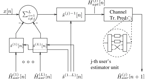
Fig. 2. Illustration of the PIC-assisted channel transfer function estimation-or prediction block, associated with thej-th user and any of theP receiver antenna elements. The PIC process is described by Equation 3.
H(j)[n]of ’true’ channel transfer factors between thej-th user’s
sin-gle transmit antenna and thep-th receiver antenna can be obtained by subtracting all the(L−1)vectors of interfering users’ estimated sig-nal contributions from the vectorxp[n]of composite received signals of theLusers, followed by normalization with thej-th user’s diagonal matrix of detected complex symbolsˇS(j)[n], yielding:
˜
H(j)
apt[n] = ˇS
(j)−1[n]
x[n]−
L
i=1
i=j
ˇ
S(i)[n] ˆH(i)
apr[n] , (3)
where for simplicity’s sake we have omitted the receiver antenna’s in-dexp. The PIC process based on Equation 3, has been further illus-trated in Figure 2. In Equation 3,Hˆ(apri) [n]∈CK×1denotes thei-th user’s vector of complexa priori(apr) channel transfer factor esti-mates predicted during the(n−1)-th OFDM symbol period for the
n-th OFDM symbol, as a function of the vectors ofa posteriori chan-nel transfer factor estimatesH˜(apti)[n−n´]associated with the previous
Ntap[t] number of OFDM symbols, which is formulated as:
ˆ
H(i)
apr[n] =f H˜apt(i)[n−1], . . . ,H˜
(i)
apt[n−N
[t]
tap]
. (4)
We will further elaborate on the specific structure of the predictor in the next section.
B. A PrioriChannel Prediction Filtering
The channel transfer function prediction along the time-direction follows the philosophy of the 2D-MMSE channel transfer function es-timation approach proposed by Liet al.[1], which in turn is based on the rank-reduction assisted 1D-MMSE channel estimation scheme proposed by Edforset al.[2].
• In a first step, in order to obtain thei-th user’s vector ofa pri-orichannel transfer factor estimates for the n-th OFDM sym-bol period during the(n−1)-th OFDM symbol period, which is denoted byHˆ(apri) [n], the vector ofa posteriorichannel trans-fer factor estimates H˜(apti)[n−1]is subjected to a unitary lin-ear inverse transform U˜[f](i)H ∈ CK×K, yielding the vector
˜
h(i)
apt[n−1]∈CK×1of CIR-relateda posterioritap values:
˜
h(i)
apt[n−1] = ˜U[f](i)HH˜
(i)
apt[n−1]. (5) From a statistical point of view the optimum unitary transform to be employed is the Karhunen-Loeve Transform (KLT) [1, 2] with
respect to the Hermitian spaced-frequency correlation matrix of a posteriorichannel transfer factor estimates, which is given by R[f](i)
apt =E{H˜
(i)
aptH˜
(i)H
apt }, when assuming the wide-sense sta-tionarity ofH˜(apti)[n]. However, for practical reasons we assume here the employment of an arbitrary unitary matrixU˜[f](i), which could be the DFT matrixWor one of the ’robust’ transforms pro-posed by Li [3].
• In a second step linearNtap[t]-tap filtering is performed in the time-direction separately for those K0 number of CIR-related components ofh˜(apti), for which the variance is significant. This is achieved by capitalizing on the current vectorh˜(apti)[n−1]and the vectorsh˜(apti)[n−n´],´n= 2, . . . , N
[t]
tapof the previous(N
[t]
tap−1) number of OFDM symbols. As a result, in the case ofestimation filtering[1] an improved estimatehˆ(apti)[n−1]ofh(i)[n−1]is obtained, although this technique was not employed here. By contrast, in case of theprediction filteringemployed here, ana prioriestimatehˆ(apri) [n]∈CK×1ofh(i)[n]is obtained. In math-ematical terms this can be formulated as:
ˆ
h(i)
apr[n] = K0−1
l=0
I(i) 1 [l]
N[tapt]
´
n=1
˜
c(prei)[´n−1, l]˜h(apti)[n−n´](6)
=
K0−1
l=0
I(i)
1 [l]h˜(apti)[n−1]˜c(prei)∗[l], (7) where the l-th sparse unity matrix I(1i)[l] ∈ CK×K, l
∈ {0, . . . , K0 −1}, exhibits a single unity entry only at the spe-cific diagonal position, for which the variance of the associated CIR-related tap in the frame ofKCIR-related taps is significant. Furthermore, in Equation 6 the variable˜c(prei)[´n−1, l] ∈ C de-notes the(´n−1)-th CIR-related tap prediction filter coefficient associated with thel-th significant CIR-related tap. In the context of the more compact notation of Equation 7, the matrixh˜(apti)[n−
1] ∈ CK×Ntap[t] is defined as h˜(i)
apt[n−1] = (˜h
(i)
apt[n−
1], . . . ,h˜(apti)[n−N
[t]
tap]), while the vector˜c
(i)
pre[k] ∈ CN [t]
tap×1
is defined as˜c(prei)[l] = (˜c(prei)∗[0, l], . . . ,˜c(prei)∗[Ntap[t] −1, l])T.
• In a last stepthe vector of CIR-related a prioritap estimates
ˆ
h(i)
apr[n] is transformed back to the OFDM frequency-domain with the aid of the unitary matrixU˜[f](i), yielding the vector of a priorichannel transfer factor estimatesHˆ(apri)[n]for then-th OFDM symbol period:
ˆ
H(i)
apr[n] = ˜U[f](i)hˆ(apri) [n]. (8) This vector ofa priorichannel transfer factor estimates is in turn employed in the detection stage during then-th OFDM symbol period. Upon substituting Equation 5 into Equation 7 and by substituting the result into Equation 8 we obtain the following relation between the vector ofa priorichannel transfer factor es-timates derived for then-th OFDM symbol and the vectors ofa posteriorichannel transfer factor estimates of the pastNtap[t] num-ber of OFDM symbols:
ˆ
H(i)
apr[n] = K0−1
l=0
T(i)
1 [l]H˜(apti)[n−1]˜c(prei)∗[l], (9) whereT(1i)∈CK×Kis given by:
T(i)
Note thatH˜(i)
apt[n−1] ∈CK×N [t]
tapis defined asH˜(i)
apt[n−1]=
( ˜H(i)
apt[n−1], . . . ,H˜
(i)
apt[n−N
[t]
tap]).
After having described the process of generating the vectors ofa posteriorianda priorichannel transfer factor estimates in Sections III-A and III-B, we will embark in Section IV on the task of optimizing the vectors˜c(prei)[l],l= 0, . . . , K0−1of predictor coefficients.
IV. RLS-BASEDADAPTATION OF THECIR-RELATEDTAP
PREDICTORCOEFFICIENTS
In [4] it was demonstrated that the vectors˜c(prei)[l],l= 0, . . . , K0−1
of predictor coefficients can be optimized off-line based on the con-cepts of ’robustness’ as proposed by Liet al.[1] for the single-user scenario, upon taking into account the recursive structure of the esti-mator. However, in order to further improve the estimator’s perfor-mance, a viable approach is adapt the predictor coefficients on a CIR-related tap-by-tap basis, using the recursive least-squares (RLS) algo-rithm. The application of the RLS algorithm to the specific prediction task encountered will be described in the following1.
Recall that the l-th CIR-related tap’s vector ˜cpre[n, l]|opt ∈ CNtap[t]×1 of optimum predictor coefficients is determined by the Wiener equation [5], namely by:
˜
cpre[n, l]|opt= ˜Rapt[t]−1[n, l]˜r
[t]
apt[n, l], (11) where R˜[aptt] [n, l] ∈ CNtap[t]×N[
t]
tap is the l-th CIR-related tap’s es-timated auto-correlation matrix and ˜r[aptt] [n, l] ∈ CN
[t]
tap×1 is the estimated cross-correlation vector, both of which are valid for the
n-th OFDM symbol period. The estimate R˜[aptt] [n, l] for the n-th OFDM symbol period could be obtained on the basis of the estimate
˜
R[t]
apt[n−1, l]associated with the(n−1)-th OFDM symbol period by evaluating [5]:
˜
R[t]
apt[n, l] =αRLSR˜apt[t] [n−1, l]+(1−αRLS)˜hapt[n−1, l]˜hHapt[n−1, l], (12) where h˜apt[n−1, l] ∈ CN
[t]
tap×1 is defined as the vector ofN[t] tap number of pastl-th CIR-related tap estimates starting with the OFDM symbol index(n−1). Furthermore, in Equation 12 the variableαRLS∈ Rdenotes the so-calledforgetting factor[5]. Similarly, the estimate
˜
r[t]
apt[n, l]for then-th OFDM symbol period can be obtained following the philosophy of Equation 12, yielding [5]:
˜
r[t]
apt[n, l] =αRLS˜r[t][n−1, l] + (1−αRLS)˜h∗apt[n, l]˜hapt[n−1, l]. (13) Instead of explicitly inverting the estimated auto-correlation matrix
˜
R[t]
apt[n]associated with then-th OFDM symbol period, an iterative update strategy based on the matrix inversion lemma - also known as the Sherman-Morrison formula - or Woodbury’s identity [5] can be invoked, which is known from the literature as the RLS algorithm [5]. In the context of our specific CIR-related tap prediction problem the RLS-algorithm is summarized below. Specifically, the so-called Kalman gain vector k[n, l] ∈ CNtap[t]×1for then-th OFDM symbol period is given by [5]:
k[n, l] = (1−αRLS) ˜R
[t]−1
apt [n−1, l]˜hapt[n−1, l]
αRLS+ (1−αRLS)˜hHapt[n−1, l] ˜R
[t]−1
apt [n−1]˜hapt[n−1, l]
,
(14)
1For reasons of space enconomy we have omitted here the index()[i]
p associ-ated with thei-th user and thep-th receiver antenna element.
which is then employed in the process of updating the inverse of the CIR-related taps’ auto-correlation matrix, namely [5]:
˜
R[t]−1
apt [n, l] =
1
αRLS ˜
R[t]−1
apt [n−1, l]−
−k[n, l]˜hHapt[n−1, l] ˜R[ t]−1
apt [n−1, l]
.(15)
Furthermore, the CIR-related tap predictor coefficient vector for the
n-th OFDM symbol period is given by [5]:
˜
cpre[n, l]|opt = ˜cpre[n−1, l]|opt+k[n, l] ˜
hapt[n, l]−
−˜cH
pre[n−1, l]˜hapt[n−1, l] ∗
, (16)
where the term in brackets denotes the prediction error associated with then-th OFDM symbol period. A standard approach for initializing the RLS algorithm [5] is that of assuming an inverse correlation matrix having a diagonal shape defined as:
˜
R[t]−1
apt [0, l] =
1
εRLS,0I, (17)
where the specific choice ofεRLS,0∈Ris less critical in our applica-tion, than the specific value of the forgetting-factorαRLS. A plausible choice for˜cpre[0, l]is for example(1,0, . . . ,0)T, which corresponds to the case of zero-forcing based one-tap prediction.
V. PERFORMANCEASSESSMENT
A. RLS-Adaptive DDCE for Single-User OFDM
In order to demonstrate the applicability of the RLS algorithm to the problem of CIR-related tap prediction in the context of DDCE we will first focus on the single-user scenario. In Figures 3 and 4 we have portrayed the evolution of thea priorichannel estimation MSE versus the OFDM symbol index for an arbitrary time segment commencing with an initial vector of prediction coefficients given by˜c(prei)[0, l] =
(1,0, . . . ,0)T, wherel= 0, . . . , K0−1. Here we have employed the
sample-spaced indoor WATM channel model of [6], where the highest CIR tap delay is given by11Ts. Hence, the number of significant CIR-related taps was chosen asK0 = 12. Furthermore, the CIR-related tap predictor’s range was equal toNtap[t] = 4. Note that for different time segments the specific MSE evolution is potentially different from that of Figures 3 and 4, but obey the same general trend. Here we have investigated the influence of the Kalman forgetting factorαRLS and of the OFDM symbol normalized Doppler frequency on thea priori channel estimation MSE performance. Specifically, in Figure 3 the OFDM symbol normalized Doppler frequency was set toFD= 0.007, while the forgetting factorαRLSwas varied. We observe in Figure 3 that for lower values ofαRLSa faster adaptation is achieved, while the residual error after adaptation is potentially higher, than that achieved with the aid of a forgetting factor of a higher value, although the latter effect is not explicitly visible in Figure 3 due to the limited time span. By contrast, in Figure 4 we have plotted thea priorichannel estimation MSE for various OFDM symbol normalized Doppler frequencies,FD, while keeping the forgetting factorαRLSconstant. As expected, thea prioriestimation MSE is increased in scenarios having a higher OFDM symbol normalized Doppler frequency, while the speed of adaptation was almost identical for the different scenarios. Note that for values of
0 64 128 192 256 OFDM symbol index
-60 -50 -40 -30 -20 -10 0
a
priori
estimation
MSE
[dB]
Fr.-Inv. Fad. SWATM, 1 Rec.-Antenna, 1 User, MPSK
RLS prediction Ideal Ref.
FD=0.007
=0.99
=0.95 =0.9
=0.8
[image:4.612.322.529.45.300.2]=0.7
Fig. 3. Evolution of thea priorichannel estimation MSE observed with the aid of the RLS prediction assisted DDCE in thesingle-reception antenna based single-user scenariofor a specific time-segment associated with the sample-spaced indoor WATM channel of [6], as a function of the OFDM symbol index, parameterized with the forgetting factorα=αRLS, for a fixed OFDM symbol normalized Doppler frequency ofFD = 0.007; the RLS predictor’s startup constant wasεRLS,0= 0.1, theNtap[t] number of CIR predictor taps was equal to four and the SNR at the reception antennas was assumed to be40dB; further-more the number of significant CIR-related taps wasK0= 12and the number of subcarriers wasK= 512.
B. RLS-Adaptive PIC-Assisted DDCE for Multi-User OFDM
Let us now focus our attention on the standard multi-user OFDM scenario of four simultaneous users, each equipped with one transmit antenna, while at the basestation (BS) a four-element antenna array is employed. The channel between each transmitreceive antenna pair -characterized in terms of its sample-spaced impulse response - and the OFDM parameters are fixed to those used by the indoor WATM system of [6]. Two detection techniques are invoked in our study, namely, the MMSE [7–9] and the M-SIC (M=2) [8–10] detection techniques. The corresponding BER- anda priorichannel estimation MSE simulation results - following the initial adaptation6of the predictor coefficients -are portrayed in Figures 5 and 6, respectively.
In the context of the BER performance assessment shown in Fig-ure 5 we observe that with the aid of the imperfect channel esti-mates produced by the RLS-adaptive PIC-assisted DDCE almost the same performance is achieved, as in case of employing ideal channel knowledge. This is particularly true for the powerful M-SIC detection algorithm, which produces relatively reliable symbol decisions and hence also a reliable remodulated reference for the RLS-adaptive PIC-assisted DDCE. By contrast, a slight BER degradation is observed, when using the less powerful MMSE detection scheme, particularly for the range of SNRs up to5dB. For higher SNRs the BER performance is also almost identical to that when using perfect channel estimates.
The benefits of a more reliable remodulated reference used in the RLS-adaptive PIC-assisted DDCE become even more evident from the
6The initial adaptation of the predictor coefficients was observed in Figures 3
and 4. After the adaptation thea priorichannel estimation MSE fluctuates around its specific mean value.
0 64 128 192 256
OFDM symbol index -60
-50 -40 -30 -20 -10 0
a
priori
estimation
MSE
[dB]
Fr.-Inv. Fad. SWATM, 1 Rec.-Antenna, 1 User, MPSK
RLS prediction Ideal Ref.
=0.8
FD=0.1
FD=0.05
FD=0.007
FD=0.01
Fig. 4. Evolution of thea priorichannel estimation MSE observed with the aid of the RLS prediction assisted DDCE in thesingle-reception antenna based single-user scenariofor a specific time-segment associated with the sample-spaced indoor WATM channel of [6], as a function of the OFDM symbol index; parameterized with the OFDM symbol normalized Doppler frequencyFDand for a fixed forgetting factor ofαRLS= 0.8; in both cases the RLS predictor’s startup constant wasεRLS,0= 0.1, theNtap[t] number of CIR predictor taps was equal to four and the SNR at the reception antennas was assumed to be40dB; furthermore the number of significant CIR-related taps wasK0 = 12and the number of subcarriers wasK= 512.
MSE performance results shown in Figure 6. Here we observe a signif-icant MSE reduction, when employing the M-SIC assisted generation of the remodulated reference, rather than that of the MMSE detector. In our specific example, which employs the sample-spaced three-path indoor WATM CIR, all of the channel’s energy is concentrated in three CIR-related taps, namely those at zero, six and eleven sampling pe-riod delays. BY contrast, at all other tap positions within the CIR window of the firstK0 = 12taps, the RLS-based adaptive predictor succeeds in effectively reducing the noise without setting these taps by ’brute force’ to zero. Hence the maximum noise reduction factor is about3/512. Note however again that in the more realistic scenario of a non-sample-spaced CIR in conjunction with employing the unitary DFT matrixWfor transforming the least-squares channel transfer fac-tor estimates from the frequency-domain to the CIR-related domain, the noise reduction is more moderate due to the effects of CIR-related domain leakage as it was discussed by van de Beeket al.[11]. More explicitly, the energy conveyed by the channel is rather spread across the different CIR-related taps.
Finally, let us comment on the specific choice of the forgetting factor ofαRLS= 0.95. As suggested during our investigations of RLS based adaptive prediction-assisted DDCE employed in single-user OFDM systems in Section V, for small values ofαRLS, the predictor may be-come unstable, as a result of which an excessive estimation MSE is ob-served. Our experiments conducted in the context of the PIC-assisted DDCE of Figure 2 further underlined that the appropriate range of
αRLSvalues has to be re-optimized when invoking an imperfect, poten-tially error-contaminated reference. Again, relatively small values of
[image:4.612.59.269.46.300.2]0 5 10 15 20 25 30 35 40 average SNR at the array elements [dB] 10-5
2 5
10-4
2 5
10-3
2 5
10-2
2 5
10-1
2 5
100
BER
Fr.-Inv. Fad. SWATM, 4 Rec.-Antennas, 4 Users, QPSK
RLS prediction
0.95 :
M-SIC
MMSE
[image:5.612.320.524.44.302.2]ideal channel knowledge
Fig. 5. BER versus SNR performance associated with the CIR-related tap-by-tap based RLS-adaptive PIC-assisted DDCE of Figure 23in the con-text of a scenario of four receiver antennas at the BS and four simultaneous users, each equipped with one transmit antenna; the channel between each transmitter-receiver antenna pair is characterized in terms of its sample-spaced impulse response and OFDM parameters by the indoor WATM channel- and system parameters of [6]; the OFDM symbol normalized Doppler frequency wasFD= 0.007; furthermore, the number of significant CIR-related taps was K0 = 12and the number of subcarriers wasK = 512; MMSE- as well as M-SIC (M=2) detection was employed at the receiver and both an ideal, error-free reference and an imperfect, error-contaminated reference was invoked in the DDCE; the RLS-specific forgetting factor was set toα=αRLS= 0.95. A choice ofαRLS= 0.95was deemed reasonable in our application.
C. Conclusions
In this paper the application of the RLS algorithm to adapting the CIR-related tap predictors’ coefficients in the context of PIC-assisted DDCE designed for OFDM systems employing multiple transmit an-tennas was studied. We characterised the influence of the RLS-specific forgetting factorαRLSand that of the channel’s OFDM symbol normal-ized Doppler frequencyFDon the estimator’s convergence properties in the single-user scenario, as shown in Figures 3 and 4. Furthermore, the estimator’s convergence experienced in the context of a multi-user scenario of four transmit antennas and four BS receiver antennas was confirmed in Figures 5 and 6. In the context of the sample-spaced three-path CIR associated with the indoor WATM channel model of [6], the BER performance achieved using the proposed estimator was almost indistinguishable from that when capitalizing on ideal channel knowledge. In the context of a non-sample spaced CIR a similarly good performance is expected upon invoking the ’robust’ transforms proposed by Li [3]. This is in contrast to the performance expected when using the DFT matrixW, which is responsible for the effects of CIR-related domain leakage [11].
REFERENCES
[1] Y. Li, L. J. Cimini, and N. R. Sollenberger, “Robust Channel Estima-tion for OFDM Systems with Rapid Dispersive Fading Channels,”IEEE Transactions on Communications, vol. 46, pp. 902–915, April 1998.
0 5 10 15 20 25 30 35 40
average SNR at the array elements [dB] -60
-50 -40 -30 -20 -10 0
a
priori
estimation
MSE
[dB]
Fr.-Inv. Fad. SWATM, 4 Rec.-Antennas, 4 Users, QPSK
RLS prediction
0.95 :
ideal ref. imperf. ref. M-SIC
MMSE
Fig. 6. A priorichannel estimation MSE versus SNR performance associ-ated with the CIR-relassoci-ated tap-by-tap based RLS-adaptive PIC-assisted DDCE of Figure 25in the context of a scenario of four receiver antennas at the BS and four simultaneous users, each equipped with one transmit antenna; the chan-nel between each transmitter-receiver antenna pair is characterized in terms of its sample-spaced impulse response and OFDM parameters by the indoor WATM channel- and system parameters of [6]; the OFDM symbol normalized Doppler frequency wasFD = 0.007; furthermore, the number of significant CIR-related taps wasK0= 12and the number of subcarriers wasK= 512; MMSE- as well as M-SIC (M=2) detection was employed at the receiver and both an ideal, error-free reference and an imperfect, error-contaminated refer-ence was invoked in the DDCE; the RLS-specific forgetting factor was set to α=αRLS= 0.95.
[2] O. Edfors, M. Sandell, J.-J. v. d. Beek, S. K. Wilson, and P. O. B¨orjesson, “OFDM Channel Estimation by Singular Value Decomposition,”IEEE Transactions on Communications, vol. 46, pp. 931–939, April 1998. [3] Y. Li and N. R. Sollenberger, “Clustered OFDM with Channel Estimation
for High Rate Wireless Data,”IEEE Transactions on Communications, vol. 49, pp. 2071–2076, December 2001.
[4] M. M¨unster and L. Hanzo, “Parallel Interference Cancellation Assisted Decision-Directed Channel Estimation for OFDM Systems Using Mul-tiple TRansmit Antennas,”IEEE Transactions on Wireless Communica-tions, submitted, 2002.
[5] T. K. Moon and W. C. Stirling,Mathematical Methods and Algorithms for Signal Processing. Prentice Hall, 2000.
[6] L. Hanzo, W. Webb, and T. Keller,Single- and Multi-carrier Quadrature Amplitude Modulation. IEEE Press- John Wiley, April 2000.
[7] Y. Li and N. R. Sollenberger, “Adaptive Antenna Arrays for OFDM Sys-tems with Cochannel Interference,”IEEE Transactions on Communica-tions, vol. 47, pp. 217–229, February 1999.
[8] M. M¨unster and L. Hanzo, “Co-Channel Interference Cancellation Tech-niques for Antenna Array Assisted Multiuser OFDM Systems,” in
Proceedings of 3G’2000 Conference, vol. 1, (London, Great Britain), pp. 256–260, IEE, March 27-29 2000.
[9] P. Vandenameele, L. V. D. Perre, M. G. E. Engels, B. Gyselinckx, and H. J. D. Man, “A Combined OFDM/SDMA Approach,”IEEE Journal on Selected Areas in Communications, vol. 18, pp. 2312–2321, Nov. 2000. [10] G. D. Golden, G. J. Foschini, R. A. Valenzuela, and P. W.
Wolni-ansky, “Detection Algorithms and Initial Laboratory Results using V-BLAST Space-Time Communication Architecture,”IEE Electronics Let-ters, vol. 35, pp. 14–16, January 1999.
[image:5.612.57.262.46.301.2]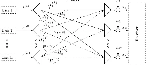
![Fig. 3.Evolution of theaid of the RLS prediction assisted DDCE in thesingle-user scenariospaced indoor WATM channel of [6], as a function of the OFDM symbol index,parameterized with the forgetting factormore the number of significant CIR-related taps wasof subcarriers was a priori channel estimation MSE observed with the single-reception antenna based for a specific time-segment associated with the sample- α = αRLS, for a fixed OFDM symbolnormalized Doppler frequency of FD = 0.007; the RLS predictor’s startupconstant was εRLS,0 = 0.1, the N[t]tap number of CIR predictor taps was equalto four and the SNR at the reception antennas was assumed to be 40dB; further- K0 = 12 and the number K = 512.](https://thumb-us.123doks.com/thumbv2/123dok_us/1013824.616261/4.612.59.269.46.300/prediction-scenariospaced-parameterized-signicant-subcarriers-estimation-symbolnormalized-startupconstant.webp)
![Fig. 6.A prioriCIR-related taps was channel estimation MSE versus SNR performance associ-ated with the CIR-related tap-by-tap based RLS-adaptive PIC-assisted DDCEof Figure 25 in the context of a scenario of four receiver antennas at the BS andfour simultaneous users, each equipped with one transmit antenna; the chan-nel between each transmitter-receiver antenna pair is characterized in termsof its sample-spaced impulse response and OFDM parameters by the indoorWATM channel- and system parameters of [6]; the OFDM symbol normalizedDoppler frequency was FD = 0.007; furthermore, the number of significant K0 = 12 and the number of subcarriers was K = 512;MMSE- as well as M-SIC (M=2) detection was employed at the receiver andboth an ideal, error-free reference and an imperfect, error-contaminated refer-ence was invoked in the DDCE; the RLS-specific forgetting factor was set toα = αRLS = 0.95.](https://thumb-us.123doks.com/thumbv2/123dok_us/1013824.616261/5.612.320.524.44.302/performance-simultaneous-characterized-normalizeddoppler-furthermore-signicant-subcarriers-contaminated.webp)