Abstract—This work studies the mixed convection heat transfer from a vertical plate in bidisperse porous media with constant wall temperature. The two-velocity two-temperature model is used to derive the governing equations. The effects of the mixed convection parameter, the inter-phase heat transfer parameter, the modified thermal conductivity ratio, and the permeability ratio on the heat transfer and flow characteristics have been studied. Results show that an increase in the mixed convection parameter, the modified thermal conductivity ratio, or the permeability ratio can effectively enhance the mixed convection heat transfer of the vertical plate in a bidisperse porous medium. Moreover, the thermal non-equilibrium effects between the f-phase and the p-phase becomes significant as the inter-phase heat transfer parameter or the mixed convection parameter is small.
Index Terms—mixed convection, bidisperse porous
medium, vertical plate, heat transfer.
I. INTRODUCTION
bidisperse porous medium is an extension of a traditional porous medium. It is of much importance because the applications of bidisperse porous medium can be found in bidisperse absorbent for enhancing absorption performance, or in bidisperse capillary wicks of a heat pipe for enhancing heat pipe heat transfer rate. There are a lot of papers on the natural or mixed convection of bidisperse porous media. Nield and Kuznetsov [1] studied the conjugate forced convection heat transfer in bi-disperse porous medium channel. Nield and Kuznetsov [2] used a two-velocity two-temperature model to study the forced convection in a channel for a bi-disperse porous medium. Nield and Kuznetsov [3] examined the problem about the onset of convection in a bidisperse porous medium. Nield and Kuznetsov [4] studied the effect of combined vertical and horizontal heterogeneity on the onset of convection in a bidisperse porous medium. Nield and Kuznetsov [5] studied the natural convection about a vertical plate embedded in a bidisperse porous medium. Rees et al. [6] studied the vertical
Manuscript received November 19, 2014; revised January 10, 2015. This work was supported by the National Science Council of Republic of China under the grant no. NSC 102-2221-E-218-025.
Ching-Yang Cheng is with the Department of Mechanical Engineering, Southern Taiwan University of Science and Technology, Yungkang, Tainan 71005, Taiwan (phone: +886-6-2683734; fax: +886-6-2895877; e-mail: cycheng@ mail.stust.edu.tw).
free convective boundary-layer flow in a bidisperse porous medium. Straughan [7] presented a study on the Nield-Kuznetsiv theory for convection in bidisperse porousmedia. Kumari and. Pop [8] studied the mixed convection boundary layer flow past a horizontal circular cylinder embedded in a bidisperse porous medium. Grosan et al. [9] studied the problem of free convection in a square cavity filled with a bisisperse porous medium. Narasimhan and Reddy [10] studied the natural convection inside a bidisperse porous medium enclosure. Narasimhan and Reddy [11] examined the resonance of natural convection inside a bidisperse porous medium enclosure. Nield and Kuznetsov [12] studied the forced convection in a channel partly occupied in a bidisperse porous medium.
This work studies the mixed convection heat transfer from a vertical plate in bidisperse porous media with uniform wall temperature. The two-velocity two-temperature formulation is used to derive the governing differential equations. The cubic spline collocation method is used to solve the boundary layer equations. The effects of the mixed convection parameter, the inter-phase heat transfer parameter, the modified thermal conductivity ratio, and the permeability ratio on the mixed convection heat transfer characteristics are studied.
II. ANALYSIS
Consider the boundary layer flow due to mixed convection heat transfer from a vertical plate embedded in a bidisperse porous medium. The x coordinate is measured in the axial direction from the leading edge of the vertical plate. The y coordinate is measured in the transverse direction from the surface of the vertical plate. The surface of the vertical plate is maintained at a constant temperature Tw , which is different from the porous medium temperature sufficiently far from the surface of the vertical plate. The velocity of free stream are denoted by U∞.
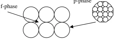
A bidisperse porous medium is a porous medium in which the solid phase is replaced by another porous medium. There are two phases, as shown in Fig. 2. One is the f-phase and the other is the p-phase. In a bidisperse porous medium, the fluid occupies all of the f-phase and a fraction of the p-phase. We denote the volume fraction of the f-phase by φ and the porosity within the p-phase by ε. Thus 1−φ is the volume fraction of the p-phase, and the volume fraction of the bidisperse porous medium by the fluid is φ+
(
1−φ)
ε. HereMixed Convection Heat Transfer from a Vertical
Plate Embedded in a Bidisperse Porous Medium
Ching-Yang Cheng
we denote Tf and Tpas the volume-averaged temperature of
the f-phase and the p-phase respectively. The volume average of the temperature over the fluid is given by
(
)
(
φ)
ε φ ε φ φ − + − + = 1 1 p f F T T [image:2.595.49.256.95.370.2]T (1)
[image:2.595.73.275.432.500.2]Fig. 1. Physical model and coordinates for a vertical plate.
Fig. 2. Sketch of a bidisperse porous medium.
The fluid properties are assumed to be constant except for density variations in the buoyancy force term. The governing equations for the flow, heat transfer near the vertical plate can be written as [5]
0 = ∂ ∂ + ∂ ∂ y v x uf f
(2) 0 = ∂ ∂ + ∂ ∂ y v x up p
(3) ⎟⎟ ⎠ ⎞ ⎜⎜ ⎝ ⎛ ∂ ∂ − ∂ ∂ = ⎟⎟ ⎠ ⎞ ⎜⎜ ⎝ ⎛ ∂ ∂ − ∂ ∂ ⎟⎟ ⎠ ⎞ ⎜⎜ ⎝ ⎛ + x v y u x v y u K K p p f f f f ς μ ς μ 1 y T * g F T F ∂ ∂
+ρ β (4)
⎟⎟ ⎠ ⎞ ⎜⎜ ⎝ ⎛ ∂ ∂ − ∂ ∂ = ⎟⎟ ⎠ ⎞ ⎜⎜ ⎝ ⎛ ∂ ∂ − ∂ ∂ ⎟⎟ ⎠ ⎞ ⎜⎜ ⎝ ⎛ + x v y u x v y u K K f f p p p p ς μ ς μ 1 y T * g F T F ∂ ∂
+ρ β (5)
( )
⎟⎟ ⎠ ⎞ ⎜⎜ ⎝ ⎛ ∂ ∂ + ∂ ∂ y T v x T uc f f f f f
ρ φ
(
p f)
f f
f hT T
y T x
T
k + −
⎟ ⎟ ⎠ ⎞ ⎜ ⎜ ⎝ ⎛ ∂ ∂ + ∂ ∂ = 2 2 2 2 φ (6)
(
)( )
⎟⎟ ⎠ ⎞ ⎜⎜ ⎝ ⎛ ∂ ∂ + ∂ ∂ − y T v x T uc p p p p p
ρ φ
1
(
)
p p p h(
Tf Tp)
yT x
T
k + −
⎟ ⎟ ⎠ ⎞ ⎜ ⎜ ⎝ ⎛ ∂ ∂ + ∂ ∂ − = 2 2 2 2
1 φ (7)
where uf and vf are the volume-averaged velocity components of the f-phase in the x and y directions. up and vp are the volume-averaged velocity components of the p-phase in the x and y directions. Kf and Kp are the permeabilities of the two phases, and ς is the coefficient for momentum transfer between the two phases. ρF is the fluid density. βT is the volumetric thermal expansion coefficient of the fluid. μ is the viscosity of the fluid. Moreover, c is the specific heat at constant pressure and k is the thermal conductivity. Moreover, h is the inter-phase heat transfer coefficient, and g* is the gravitational acceleration.
The boundary conditions for this problem are 0
=
y
:
Tf =Tw,
Tp =Tw,
vp =0,
vf =0(8)
∞ →
y
:
Tf →T∞,
Tp →T∞,
up →U∞,
uf →U∞(9) Here we introduce the stream functions, ψf and ψp, to satisfy the relations:
y uf f
∂ ∂ = ψ ,
x
vf f
∂ ∂ − = ψ ,
y
up p
∂ ∂ = ψ ,
x
vp p
∂ ∂ −
= ψ (10)
Moreover, we define the nondimensional variables and parameters:
l x x= ,
l y
y= ,
( )
(
)
pp p p k c ψ φ ρ ψ − = 1 ,
( )
f f f f k c ψ φ ρψ = ,
∞ ∞ − − = T T T T w f f θ , ∞ ∞ − − = T T T T w p p θ (11)
Eqs. (2)-(7) become the following equations:
(
)
⎟⎟ ⎠ ⎞ ⎜ ⎜ ⎝ ⎛ ∂ ∂ + ∂ ∂ + 2 2 2 2 1 y x f f f ψ ψσ ⎟⎟
⎠ ⎞ ⎜ ⎜ ⎝ ⎛ ∂ ∂ + ∂ ∂ − 2 2 2 2 y x p p f ψ ψ βσ
( )
⎥ ⎦ ⎤ ⎢ ⎣ ⎡ ∂ ∂ − + ∂ ∂ = y yRal τ θf 1 τ θp (12)
∗
g
∞
⎟ ⎟ ⎠ ⎞ ⎜ ⎜ ⎝ ⎛ ∂ ∂ + ∂ ∂ − 2 2 2 2 y x f f f ψ ψ
σ ⎟⎟
⎠ ⎞ ⎜ ⎜ ⎝ ⎛ ∂ ∂ + ∂ ∂ ⎟⎟ ⎠ ⎞ ⎜⎜ ⎝ ⎛ + + 2 2 2 2 1 y x K p p f r ψ ψ σ β
( )
⎥ ⎦ ⎤ ⎢ ⎣ ⎡ ∂ ∂ − + ∂ ∂ = y yRal τ θf 1 τ θp (13)
⎟ ⎟ ⎠ ⎞ ⎜ ⎜ ⎝ ⎛ ∂ ∂ ∂ ∂ − ∂ ∂ ∂ ∂ y x x y f f f
f θ ψ θ
ψ φ
(
p f)
f f
H y
x θ θ
θ θ − + ⎟ ⎟ ⎠ ⎞ ⎜ ⎜ ⎝ ⎛ ∂ ∂ + ∂ ∂ = 2 2 2 2 (14) ⎟⎟ ⎠ ⎞ ⎜⎜ ⎝ ⎛ ∂ ∂ ∂ ∂ − ∂ ∂ ∂ ∂ y x x y p p p
p θ ψ θ
ψ φ
(
f p)
p
p H
y
x γ θ θ
θ θ − + ⎟ ⎟ ⎠ ⎞ ⎜ ⎜ ⎝ ⎛ ∂ ∂ + ∂ ∂ = 2 2 2 2 (15)
where the Darcy-Rayleigh number and the Peclet number based on the characteristic length l and properties in the f-phase are given by
(
)
( )
ff w f T F
l k c
T T l K g Ra ρ μφ β
ρ ∗ − ∞
=
, ,
( )
f fl k c
l U Pe ρ φ ∞ = (16)
Moreover, the modified thermal capacity ratio, the f-phase momentum transfer parameter, the porosity parameter, permeability ratio, the modified thermal conductivity ratio, and the inter-phase heat transfer parameter are respectively defined as
(
) ( )
( )
pf f p c k c k ρ φ ρ φ
β = 1− ,
μ ς σ f f K = ,
(
φ)
ε φ φ τ − + =1 ,
f p r
K K K = ,
(
)
p f k k φ φ γ − =1 , kf
hl Hˆ
φ
2
= (17)
The associated boundary conditions are given by
0 =
y : ψf =0, ψp =0, θf =1, θp =1 (18)
∞ →
y : f Pel
y → ∂ ∂ψ
,
β ψp Pel
y → ∂ ∂
, θf →0, θp →0
(19) Here we use the coordinate transformation given by
x
x~= , y~=Ral12y, ψ~f =Ral−12ψ f, ψ~p =Ral−12ψp
(20) Substituting Eq. (20) into Eqs. (12)-(15) and using
boundary- layer approximation, we can obtain the following boundary-layer equations:
(
)
2 22 2 1 y~ ~ y~ ~ p f f f ∂ ∂ − ∂ ∂
+σ ψ βσ ψ
(
)
y~ y~ p f ∂ ∂ − + ∂ ∂
=τ θ 1 τ θ (21)
2 2 2 2 1 y~ ~ Kr y~ ~ p f f f ∂ ∂ ⎟ ⎠ ⎞ ⎜ ⎝ ⎛ + + ∂ ∂
−σ ψ β σ ψ
(
)
y~ y~ p f ∂ ∂ − + ∂ ∂=τ θ 1 τ θ (22)
(
f p)
f H
y~ θ θ
θ − − ∂ ∂ 2 2 ⎟ ⎟ ⎠ ⎞ ⎜ ⎜ ⎝ ⎛ ∂ ∂ ∂ ∂ − ∂ ∂ ∂ ∂ = y x~ ~ x~ y~ ~ f f f
f θ ψ θ
ψ
φ (23)
(
p f)
p H
y~ γ θ θ
θ − − ∂ ∂ 2 2 ⎟ ⎟ ⎠ ⎞ ⎜ ⎜ ⎝ ⎛ ∂ ∂ ∂ ∂ − ∂ ∂ ∂ ∂ = y~ x~ ~ x~ y~ ~ p p p
p θ ψ θ
ψ
φ (24)
The associated boundary conditions are given by
0 =
y~ : ψ~f =0, ψ~p=0, θf =1, θp =1 (25)
∞ →
y~ : M2
y~ ~ f → ∂ ∂ψ , β
ψ M2
y~ ~
p →
∂ ∂
, θf →0, θp →0
(26) where the mixed convection parameter and the inter-phase
heat transfer parameter are
2 1 ⎟⎟ ⎠ ⎞ ⎜⎜ ⎝ ⎛ = l l Ra Pe M , l Ra Hˆ
[image:3.595.320.539.379.695.2]H= (27)
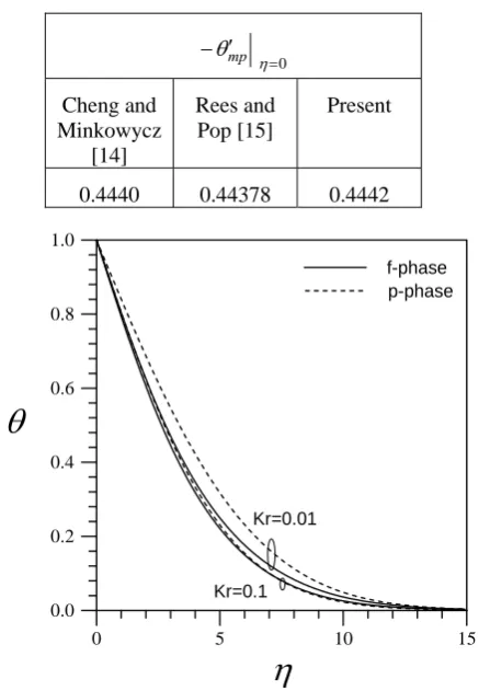
Table 1. Comparison of values of
0
=
′ −
η
θmp for free convection heat transfer from a vertical plate with constant wall temperature in mono-disperse porous media.
0 = ′ − η θmp Cheng and Minkowycz [14] Rees and Pop [15] Present
[image:3.595.48.293.442.593.2]0.4440 0.44378 0.4442
Fig. 3. The effect of the permeability ratio on the temperature profiles for the f-phase and the p-phase for ξ=0.2 ,
6 0.
H= ,M =0.3, β =1, γ =0.2, σf =0.01, φ=0.2, 4
0.
=
ε , and τ=0.3846.
We may reduce Eqs. (21)-(24) to a form more convenient for numerical solution by the transformation:
η
θ
0 5 10 15
x~
=
ξ , η= y~/ξ12, ψ~ ξ g
( )
ξ,ηp = 12 , ψ~f =ξ12f
( )
ξ,η(28) Substituting Eq. (28) into Eqs. (21)-(24), we obtain the
following equations:
(
1+σf)
f′−βσfg′=τθf +(
1−τ)
θp+M (29)(
1)
(
)
11 −
− + ′= + − +
+ ′
−σf f β Kr σf g τθf τ θp MKr (30)
(
f p)
f
f φ fθ Hξθ θ
θ′′+ ′ − −
2 1
⎟ ⎟ ⎠ ⎞ ⎜
⎜ ⎝ ⎛
∂ ∂ ′ − ∂ ∂ ′ =
ξ θ ξ θ ξ
φ f f f f (31)
(
)
p(
p f)
p φ gθ γHξθ θ
θ′′+ 1− ′ − −
2 1
(
)
⎟⎟⎠ ⎞ ⎜
⎜ ⎝ ⎛
∂ ∂ ′ − ∂ ∂ ′ − =
ξ θ ξ θ ξ
φ g p p g
1 (32)
where primes denote differentiation with respect to η. Note that the momentum equations have been integrated once about η to obtain Eqs. (29) and (30).
The boundary conditions are transformed to 0
=
η : f =0, g=0, θf =1, θp=1 (33)
∞ →
η : f′→M2,
β 2 M
g′→ , θf →0, θp→0 (34)
Moreover, the local Nusselt numbers for the f-phase and the p-phase can be derived as
( )
,0 RaNu
f x
f =−θ ′ ξ (35)
( )
,0 RaNu
p x
p =−θ ′ ξ
(36)
where Nuf =hfx kf and Nup =hpx kp . Note that hf and hp are the convection heat transfer coefficient for the f-phase and the p-phase. The Darcy-Rayleigh number based on the streamwise coordinate x and properties in the f-phase is given by
(
)
( )
f ff w
T F
x k c
x K T T g Ra
ρ φ μ
β
ρ ∗ − ∞
= (37)
III. RESULTS AND DISCUSSION
The transformed governing partial differential equations, Eqs. (31) and (32), and the boundary conditions, Eqs. (33) and (34), can be solved by the cubic spline collocation method [13]. The velocities f′ and g′ are calculated from the momentum equations, Eqs. (29) and (30). Moreover, the Simpson’s rule for variable grids is used to calculate the values of f and g at every position from the boundary conditions, Eqs. (33) and (34). At every position, the iteration
process continues until the convergence criterion for all the variables, 6
10− , is achieved. Variable grids with 350 grid points are used in the η-direction. The optimum value of boundary layer thickness is used. Moreover, the backward finite difference is used to calculate the derivative about the streamwise coordinate. Table 1 shows the numerical values of
0
=
′ −
η
[image:4.595.324.535.205.423.2]θmp for natural convection heat transfer of a vertical smooth plate in mono-disperse porous media with constant wall temperature. It is shown that the present results are in excellent agreement with the results reported by Cheng and Minkowycz [14] and Rees and Pop [15].
Fig. 4. The effect of the inter-phase heat transfer parameter on the temperature profiles for the f-phase and the p-phase for
2 0.
=
ξ , M =0.3, Kr =0.01, β=1, γ =0.2, σf =0.01, 2
0.
=
φ , ε =0.4, and τ =0.3846.
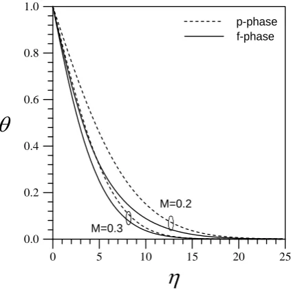
Fig. 5. The effect of the mixed convection parameter on the temperature profiles for the f-phase and the p-phase for
2 0.
=
ξ , H =0.6, Kr =0.01, β =1, γ =0.2, σf =0.01,
2 0.
=
φ , ε=0.4, and τ=0.3846.
η
θ
0 5 10 15 20 25
0.0 0.2 0.4 0.6 0.8 1.0
M=0.2 M=0.3
p-phase f-phase
η
θ
0 5 10 15
0.0 0.2 0.4 0.6 0.8 1.0
p-phase
f-phase
[image:4.595.325.537.505.715.2]Fig. 3 shows the effect of the permeability ratio Kr on the temperature profiles for the f-phase and the p-phase. As the permeability ratio is increased, both the boundary layers of the solid phase and the fluid phase become thinner, thus increasing the temperature gradients of the f-phase and the p-phase. Moreover, a decrease in the permeability ratio tends to increase the temperature difference between the f-phase and the p-phase, thus enhancing the thermal non-equilibrium effect.
Fig. 4 shows the effect of the inter-phase heat transfer parameter H on the temperature profiles for the f-phase and the p-phase. Results show that a decrease in the inter-phase heat transfer parameter tends to increase the temperature difference between the f-phase and the p-phase; thus the thermal non-equilibrium effect becomes more significant. In other words, when the inter-phase heat transfer parameter is small, the temperature field corresponding to the p-phases occupies a much greater region than does the temperature field of the f-phase.
[image:5.595.52.292.409.624.2]Fig. 5 shows the effect of the mixed convection parameter M on the temperature profiles for the f-phase and the p-phase. As the mixed convection parameter is increased, both the boundary layers of the solid phase and the fluid phase become thinner, thus increasing the temperature gradients of the f-phase and the p-phase. Moreover, a decrease in mixed convection parameter tends to increase the temperature difference between the f-phase and p-phase, thus enhancing the thermal non-equilibrium effect.
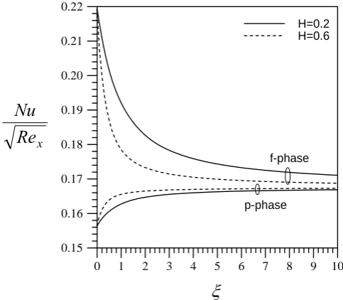
Fig. 6. The effect of the permeability ratio on the local Nusselt numbers for the f-phase and the p-phase for H =0.6,
3 0.
M = , β=1, γ =0.2, σf =0.01, φ=0.2, ε =0.4, and τ=0.3846.
Fig. 6 shows the effect of the permeability ratio Kron the local Nusselt numbers for the f-phase and the p-phase. Fig. 6 shows that an increase in the permeability ratio tends to increase both the local Nusselt numbers for the f-phase and the p-phase. In other words, the heat transfer rate for the bidisperse porous medium can be effectively enhanced by raising the permeability ratio. Moreover, as the coordinate is
small, the local Nusselt number for the f-phase is much higher than that for the p-phase. The two phases are in the state of thermal non-equilibrium. As the streamwise coordinate is increased, the local Nusselt number for the f-phase approaches that for the p-phase. This means that the bidisperse porous medium gradually approaches the state of thermal equilibrium far downstream.
Fig. 7. The effect of the inter-phase heat transfer parameter on the local Nusselt numbers for the f-phase and the p-phase for M =0.3 , Kr =0.01 , β=1, γ =0.2 , σf =0.01,
2 0.
=
φ , ε=0.4, and τ=0.3846.
Fig. 8. The effect of the modified thermal conductivity ratio on the local Nusselt numbers for the f-phase and the p-phase for H =0.6, M =0.3, Kr =0.01 , β=1, σf =0.01,
2 0.
=
φ , ε=0.4, and τ=0.3846.
Fig. 7 shows the effect of the inter-phase heat transfer parameter H on the local Nusselt numbers for the f-phase and the p-phase. A decrease in the inter-phase heat transfer parameter increases the difference between local Nusselt numbers for the f-phase and the p-phase. This means that
x
Re
Nu
ξ
0 1 2 3 4 5 6 7 8 9 10 0.15
0.16 0.17 0.18 0.19 0.20 0.21 0.22
f-phase
p-phase H=0.2 H=0.6
x
Re
Nu
ξ
0 1 2 3 4 5 6 7 8 9 10 0.15
0.16 0.17 0.18 0.19 0.20 0.21 0.22
γ=0.2 γ=0.5
x
Re
Nu
ξ
0 1 2 3 4 5 6 7 8 9 10 0.15
0.16 0.17 0.18 0.19 0.20 0.21 0.22 0.23
Kr=0.01 Kr=0.1
[image:5.595.310.551.438.651.2]lower values of the inter-phase heat transfer parameter can leads to the state of thermal non-equlibrium between the p-phase and the f-phase of the bidisperse porous medium.
Fig. 8 shows the effect of the modified thermal conductivity ratio γ on the local Nusselt numbers for the f-phase and the p-phase. An increase in the modified thermal conductivity ratio tends to increase both the local Nusselt number for the f-phase and local Nusselt number for the p-phase. In other words, the heat transfer rate for the bidisperse porous medium can be effectively enhanced by raising the modified thermal conductivity ratio.
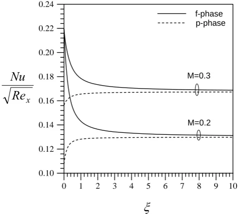
[image:6.595.53.294.301.516.2]Fig. 9 shows the effect of the mixed convection parameter M on the local Nusselt numbers for the f-phase and the p-phase. Increasing the mixed convection parameter tends to increase both the local Nusselt number for the f-phase and local Nusselt number for the p-phase. In other words, the heat transfer rate for the bidisperse porous medium can be effectively enhanced by raising the mixed convection parameter.
Fig. 9. The effect of the mixed convection parameter on the local Nusselt numbers for the f-phase and the p-phase for
6 0.
H = , Kr =0.01, β=1, γ =0.2, σf =0.01, φ=0.2,
4 0.
=
ε , and τ=0.3846.
IV. CONCLUSION
This work has studied the mixed convective boundary-layer flow over a vertical plate embedded in a bidisperse porous medium with constant wall temperature. This work uses the two-velocity two-temperature model and the coordinate transformation to derive the boundary layer governing partial differential equations. The cubic spline collocation method is then used to solve the boundary layer governing equations. The effects of the mixed convection parameter, the inter-phase heat transfer parameter, the modified thermal conductivity ratio, and the permeability ratio on the mixed convection heat transfer characteristics have been studied. Results show that an increase in the mixed convection parameter, the modified thermal conductivity ratio, or the permeability ratio can effectively enhance the mixed convection heat transfer of the vertical plate in a
bidisperse porous medium. Moreover, the thermal non-equilibrium effects between the f-phase and the p-phase in the bidisperse porous medium becomes significant as the inter-phase heat transfer parameter or the mixed convection parameter is small.
References
[1] D.A. Nield and A. V. Kuznetsov, “Forced Convection in Bi-disperse Porous Medium Channel: a Conjugate Problem,” International Journal
of Heat and Mass Transfer, vol.47, pp. 5375-5380, 2004.
[2] D.A D.A. Nield and A. V. Kuznetsov, “A Two-velocity Two-temperature Model for a Bi-disperse Porous Medium: Forced Convection in a Channel,” Transport in Porous Media, vol.59, pp. 325-339, 2005.
[3] D.A. Nield and A. V. Kuznetsov, “The Onset of Convection in a Bidisperse Porous Medium,” International Journal of Heat and Mass Transfer, vol.49, pp. 3068-3074, 2006.
[4] D. A. Nield and A. V. Kuznetsov, “The Effect of Combined Vertical and Horizontal Heterogeneity on the Onset of Convection in a Bidisperse Porous Medium,” International Journal of Heat and Mass Transfer, vol.50, pp. 3329-3339, 2007.
[5] D. A. Nield and A. V. Kuznetsov, “Natural Convection about a Vertical Plate Embedded in a Bidisperse Porous Medium,” International Journal of Heat and Mass Transfer, vol.51, pp. 1658-1664, 2008.
[6] D.A.S. Rees, D.A. Nield, and A. V. Kuznetsov, “Vertical Free Convective Boundary-layer Flow in a Bidisperse Porous Medium,”
ASME Journal of Heat Transfer, vol.130, pp. 092601.1-092601.9, 2008.
[7] B. Straughan, “On the Nield-Kuznetsiv Theory for Convection in Bidisperse Porous Media,” Transport in Porous Media, vol.77, pp. 159-168, 2009.
[8] Kumari, M. and Pop, I., “Mixed Convection Boundary Layer Flow past a Horizontal Circular Cylinder Embedded in a Bidisperse Porous Medium,” Transport in Porous Media, vol.77, pp.287-303, 2009. [9] T. Grosan, I. Pop, and D. B. Ingham, “Free Convection in a Square
Cavity Filled with a Bidisperse Porous Medium,” International Journal
of Thermal Sciences, vol.48, pp.1876-1883, 2009.
[10] A. Narasimhan and B.V.K. Reddy, “Natural Convection Inside a Bidisperse Porous Medium Enclosure,” ASME Journal of Heat Transfer, Vol.132, pp. 012502.1-012502.9, 2010.
[11] A. Narasimhan and B.V.K. Reddy, “Resonance of Natural Convection inside a Bidisperse Porous Medium Enclosure,” ASME Journal of Heat
Transfer, vol.133, pp. 042601.1-042601.9, 2011.
[12] D. A. Nield and A. V. Kuznetsov, “Forced Convection in a Channel Partly Occupied in a Bidisperse Porous Medium: Symmetric Case,”
ASME Journal of Heat Transfer, vol.133, pp. 072601.1-072601.9, 2011.
[13] P. Wang and R. Kahawita, “Numerical Integration of a Partial Differential Equations Using Cubic Spline,” International Journal of Computers and Mathematics, vol.13, pp. 271-286, 1983.
[14] P. Cheng, W.J. Minkowycz, “Free Convection about a Vertical Plate Embedded in a Porous Medium with Application to Heat Transfer from a Dyke,” Journal of Geophysics Research, vol.82, pp. 2040-2044, 1977. [15] D.A.S. Rees, I. Pop, “Vertical Free Convective Boundary-layer Flow
in a Porous Medium Using a Thermal Nonequilibrium Model,” Journal of Porous Media, vol. 3, pp. 31-44, 2000.
ξ
0 1 2 3 4 5 6 7 8 9 10 0.10
0.12 0.14 0.16 0.18 0.20 0.22 0.24
M=0.3
M=0.2 p-phase f-phase
x