Abstract—An experimental study has been carried out on axially loaded short and slender high strength concrete columns confined with carbon fiber-reinforced polymer (CFRP) sheets. A total of 48 specimens were loaded to failure in axial compression and investigated in both axial and transverse directions. The parameters considered for circular and square columns are: the number of wrap layers and the slenderness of the columns. Compressive stress, axial and hoop strains have been recorded to evaluate the stress-strain relationship, ultimate strength and ductility of the specimens. Results demonstrate that composite wrapping can enhance the structural performance of RC columns in terms of both maximum strength and ductility. The efficiency of the confinement was very sensitive to the specimen cross section geometry but increase with the number of CFRP layers. Increasing the strengthened column's slenderness ratio, within the values considered, shows small effect on their load carrying and deformation capacities.
Keywords— CFRP, confinement, RC Column, strength.
I. INTRODUCTION
here is a need to employ innovative materials which can provide quick and reliable solutions to the problems of civil infrastructures that are deteriorating due to environmental effects and steadily increasing load levels. With the recent advances in composite materials technology, fiber reinforced polymers (FRP) have opened new horizons in the civil engineering field to repair and retrofit existing infrastructures or to design new infrastructures
Carbon fiber reinforced plastics sheets or plates are well suited to this application because of their high strength-to-weight ratio, good fatigue properties, and excellent resistance to corrosion. Their application in civil engineering structures has been growing rapidly in recent years, and is becoming an effective solution for strengthening deteriorated concrete
Abdesselam Bourouz1 is with the Civil Engineering Department, Laboratory of Materials and Durability of Constructions (L.M.D.C), University of Constantine 1, Constantine 25000, Algeria, (e-mail: [email protected]).
Nasr-Edine Chikh2 is with the Civil Engineering Department, Laboratory
of Materials and Durability of Constructions (L.M.D.C), University of Constantine 1, Constantine 25000, Algeria, (corresponding author’s phone: 00213773703026; e-mail: [email protected]).
Riad Benzaid3 is with the Civil Engineering Department, Laboratory of
Geology Engineering (L.G.G), University of Jijel, Jijel 18000, Algeria. (e-mail: Benzai-riad @ yahoo.fr).
Abdelkrim Laraba4, is with the Civil Engineering Department, Laboratory of Materials and Durability of Constructions (L.M.D.C), University of Constantine 1, Constantine 25000, Algeria, (e-mail: [email protected])
members. Because CFRPs are quickly and easily applied, their use minimizes labor costs and can lead to significant savings in the overall costs of a project.
During the last decade, the use of FRP composites has been successfully promoted for external confinement of reinforced concrete (RC) columns all over the world. Several studies on the performance of FRP wrapped columns have been conducted, using both experimental and analytical approaches [1]-[6]. Such strengthening technique has proved to be very effective in enhancing their ductility and axial load capacity. However, most of the available experimental data regarding FRP-confined columns have been generated from tests on small-scale concrete cylinders with normal strength. The data available for columns of square or rectangular cross sections have increased over recent years but are still limited [7]-[9]. Also the validation of these results and their applicability to large-scale RC columns is of great practical interest. Published work in this field is relatively few [10], [11]. More research investigation is needed on this subject to study the effect of slenderness for high strength concrete columns.
This study deals with a series of tests on circular and square plain concrete (PC) and reinforced concrete (RC) columns strengthened with CFRP sheets. A total of 48 concrete specimens were tested under axial compression. The data recorded included the compressive loads, axial strains, and radial strains. The parameters considered are the number of composite layers (1 and 3) and slenderness ratio of the column L/D (2; 5.08 and 6.45) for circular shape and L/a (2; 4 and 7.14) for square shape. To comply with existing RC members in practice, where reduced cover is often present, the corners for all prismatic specimens were almost kept sharp for CFRP application.
II.EXPERIMENTAL STUDY
A.Materials
The concrete mix used to prepare testing specimens is indicated in Table I.
The carbon-fiber sheets used were the SikaWrap-230C product, a unidirectional wrap. The manufacturer’s guaranteed tensile strength for this CFRP is 4300 MPa, with a tensile modulus of 238 GPa, an ultimate elongation of 18 ‰ and a fiber thickness of 0.13mm. The Sikadur-330 epoxy resin was used to bond the carbon fabrics over the square columns.
Confinement of High Strength Concrete
Columns with CFRP Sheets
A. Bourouz
1, N. Chikh
2, R. Benzaid
3and A. Laraba
4T
WCE 2014, July 2 - 4, 2014, London, U.K.
ISBN: 978-988-19253-5-0
Eight series of experiments were performed to investigate the behavior of PC and RC columns confined by CFRP composite.
TABLE I
CONCRETE MIXTURE PROPORTIONS
Concrete strength f’co, MPa 61,81
Cement, kg/m3 450
Water, kg/m3 170.00
Crushed gravel, kg/m3
Ø 4/6 115.60
Ø 6/12 242.80
Ø 12/20 728.50
Sand Ø 0/4, kg/m3 685.60
Sika Viscorete-Tempo12 , ml 1550.00
W/C 0.38
TABLE II DETAILS OF TEST SPECIMENS
Specimen designation
Slender ratio
L/D or L/a
Nominal dimensions
(D x L or a x a x L) [mm]
Number of layers
Number of specimens
CPC. x0 2 160 x 320 0 2 CPC. x1 2 160 x 320 1 2 CPC. x3 2 160 x 320 3 2 CRC. x0 2 160 x 320 0 2 CRC. x1 2 160 x 320 1 2 CRC. x3 2 160 x 320 3 2 CRC. y0 5.08 197 x 1000 0 2 CRC. y1 5.08 197 x 1000 1 2 CRC. y3 5.08 197 x 1000 3 2 CRC. z0 6.45 155 x 1000 0 2 CRC. z1 6.45 155 x 1000 1 2 CRC. z3 6.45 155 x 1000 3 2 SPC. x0 2 140 x 140 x 280 0 2 SPC. x1 2 140 x 140 x 280 1 2 SPC. x3 2 140 x 140 x 280 3 2 SRC. x0 2 140 x 140 x 280 0 2 SRC. x1 2 140 x 140 x 280 1 2 SRC. x3 2 140 x 140 x 280 3 2 SRC. y0 4 140 x 140 x 560 0 2 SRC. y1 4 140 x 140 x 560 1 2 SRC. y3 4 140 x 140 x 560 3 2 SRC. z0 7.14 140 x 140 x 1000 0 2 SRC. z1 7.14 140 x 140 x 1000 1 2 SRC. z3 7.14 140 x 140 x 1000 3 2
Table II summarizez the specimens involved in the experimental program.
For all RC specimens the diameter of longitudinal and transverse reinforcing steel bars were respectively 12 mm and 8 mm. The longitudinal steel ratio was constant for all specimens and equal to 2.25%.The yield strength of the longitudinal and transversal reinforcement was 500 MPa and 235 MPa, respectively.
The specimen notations are as follows. The first two letters refer to the cross section shape: and C for circular and S for
square, followed by type of concrete: PC for plain concrete and RC for reinforced concrete. The next letter indicates the slenderness ratio: x for L/a=2 (or L/D=2), y for L/a=4 (or L/D=5.08) and z for L/a=7.14 (or L/D=6.45). The last number specifies the number of layers.
B.Specimen Preparation
After concrete columns were fully cured, FRP wrapping was performed according to the procedure specified by the manufacturer. The CFRP jackets were applied to the specimens by manual wet lay-up process. The concrete specimens were cleaned and completely dried before the resin was applied. The epoxy resin was directly applied onto the substrate. The fabric was carefully placed into the resin with gloved hands and smooth out any irregularities or air pockets using a plastic laminating roller. The roller was continuously used until the resin was reflected on the surface of the fabric, an indication of fully wetting. A second layer of resin was applied to allow the impregnation of the CFRP. The following layer is applied in the same way. Finally, a layer of resin was applied to complete the operation.
Each layer was wrapped around the column with an overlap of ¼ of the perimeter to avoid sliding or deboning of fibers during tests. The wrapped specimens were left at room temperature for 1 week before testing.
C.Test Procedures
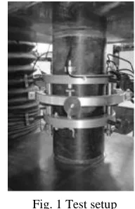
Specimens were loaded under a monotonic uni-axial compression load up to failure. The load was applied at a rate corresponding to 0.24 MPa/s and was recorded with an automatic data acquisition system. Axial and lateral strains were measured using extensometers. The test setup for the various specimens is shown in Fig. 1.
[image:2.612.386.482.471.619.2].
Fig. 1 Test setup
III.TEST RESULTS AND DISCUSSION
columns, failure occurred at one of the corners, because of the high stress concentration at these locations.
For short specimens, the fiber rupture starts mainly in their central zone and then propagates towards other sections. Regarding slender specimens, the collapse was mostly concentrated in their end regions, indicating that the greater the slender ratio, the smaller the area of CFRP ruptured.
[image:3.612.82.261.348.735.2]
Fig. 2 Failure of CFRP confined specimens
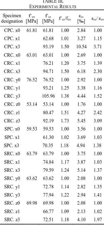
TABLE III, EXPERIMENTAL RESULTS
Specimen designation
f’co
[MPa] f’cc
[MPa] f’cc/fco εcc
[‰] εcc/ εco
CPC. x0 61.81 61.81 1.00 2.84 1.00
CPC. x1 62.68 1.01 3.27 1.15
CPC. x3 93.19 1.50 10.54 3.71
CRC. x0 63.01 63.01 1.00 2.69 1.00
CRC. x1 76.21 1.20 3.75 1.39
CRC. x3 94.71 1.50 6.18 2.30
CRC. y0 76.52 76.52 1.00 2.92 1.00
CRC. y1 93.21 1.25 3.38 1.16
CRC. y3 105.96 1.38 4.44 1.52
CRC. z0 53.14 53.14 1.00 1.76 1.00
CRC. z1 80.47 1.51 4.27 2.42
CRC. z3 92.19 1.73 5.45 3.09
SPC. x0 59.53 59.53 1.00 3.56 1.00
SPC. x1 61.30 1.02 3.69 1.03
SPC. x3 70.35 1.18 4.94 1.38
SRC. x0 63.79 63.79 1.00 3.75 1.00
SRC. x1 74.84 1.17 3.87 1.03
SRC. x3 79.59 1.24 5.14 1.37
SRC. y0 63.62 63.62 1.00 2.08 1.00
SRC. y1 72.78 1.14 2.82 1.35
SRC. y3 77.94 1.22 2.94 1.41
SRC. z0 69.98 69.98 1.00 2.08 1.00
SRC. z1 66.77 1.09 2.13 1.02
SRC. z3 72.51 1.18 4.10 1.97
At ultimate load, when confinement action was no longer provided due to FRP fracture, the internal steel started buckling and the crushed concrete fell down between the fractured FRP. This indicates that the concrete core is significantly damaged (but yet confined) even before reaching ultimate load.
For all confined specimens, delamination was not observed at the overlap location of the jacket, which confirmed the adequate stress transfer over the splice. The strain values observed for the jacket tensile failure were quite lower that the FRP failure strain, as many authors have already published.
Some average experimental results are reported in Table III, with the increase in terms of compressive strength (f’cc/fco) and ductility (εcc/εco), intended as ultimate axial displacement.
Representative stress-strain curves for each series of tested CFRP-wrapped specimens are reported in Fig. 3 for circular specimens and in Fig. 4 for square specimens. These figures give the axial stress versus the axial and lateral strains for specimens with zero, 1 and 3 layers of CFRP wrap considering various slenderness ratios.
A. Stress-Strain Response
All CFRP strengthened specimens showed a typical bilinear trend. The first zone is essentially a linear response governed by the stiffness of the unconfined concrete, which indicates that no confinement is activated in the CFRP wraps since the lateral strains in the concrete are very small. Hence the confined and the unconfined specimens behave in the same manner, irrespective of the number of layers. After reaching the maximum load point, the unconfined concrete specimens show a sudden drop in stiffness and strength. The increase of load produces large lateral expansions, and consequently the CFRP wrap reacts accordingly and a confining action is created on the concrete core. It should be noted that the confinement pressure is activated at higher load (around 70%80% of the ultimate value). In the case of circular columns the section is fully confined, therefore the capacity of confining pressure is able to limit the effects of the deteriorated concrete core, which allows reaching higher stresses. Instead in the cases of square sections, the confining action is mostly limited at the corners, producing therefore a confining pressure not sufficient to overcome the effect of concrete degradation.
In the second zone, the concrete is fully cracked and the activated CFRP confinement provides additional load carrying capacity by keeping the concrete core intact. The stress-strain curve here increases linearly up to failure. The stiffness of the specimen in this zone depends on the modulus of elasticity of the CFRP material and on the level of confinement.
No distinct post behaviour is observed for specimens with higher slenderness ratio. On overall, both ultimate compressive strength and ultimate strain are variably enhanced depending on the number of layers and the slenderness ratio. Effect of slenderness ratio
In the second zone, the concrete is fully cracked and the activated CFRP confinement provides additional load carrying capacity by keeping the concrete core intact. The stress-strain WCE 2014, July 2 - 4, 2014, London, U.K.
ISBN: 978-988-19253-5-0
Fig.3 Stress-strain curves for circular columns
Fig.3 Stress-strain curves for circular columns
Fig.4 Stress-strain curves for square columns
Fig.4 Stress-strain curves for square columns 0
10 20 30 40 50 60 70 80 90 100
-10 -8 -6 -4 -2 0 2 4 6 8 10 Lateral strain (‰ ) Axial strain (‰ )
S
tr
e
s
s
(
M
P
a
)
SRC.x series
0 layer 1layer 3 layers
0 10 20 30 40 50 60 70 80 90 100
-10 -8 -6 -4 -2 0 2 4 6 8 10
Lateral strain (‰ ) Axial strain (‰ )
S
tr
e
s
s
(
M
P
a
)
SRC.y series
0 layer 1layer
3 layers
0 10 20 30 40 50 60 70 80 90 100
-10 -8 -6 -4 -2 0 2 4 6 8 10
Lateral strain (‰ ) Axial strain (‰ )
S
tr
e
s
s
(
M
P
a
)
SRC.z series
0 layer 1layer
3 layers 0
10 20 30 40 50 60 70 80 90 100
-10 -8 -6 -4 -2 0 2 4 6 8 10
Lateral strain (‰ ) Axial strain (‰ )
S
tr
e
s
s
(
M
P
a
)
CRC.x series
0 layer 1layer
3 layers
0 10 20 30 40 50 60 70 80 90 100
-10 -8 -6 -4 -2 0 2 4 6 8 10
Lateral strain (‰ ) Axial strain (‰ )
S
tr
e
s
s
(
M
P
a
)
CRC.z series
0 layer 1layer
3 layers 0
10 20 30 40 50 60 70 80 90 100 110
0 2 4 6 8 10
Axial strain (‰ )
S
tr
e
s
s
(
M
P
a
)
CRC.y series
0 layer 1layer
curve here increases linearly up to failure. The stiffness of the specimen in this zone depends on the modulus of elasticity of the CFRP material and on the level of confinement.
The comparison of results recorded from wrapped RC specimens having equal cross section, shows that the increase of the slenderness ratio within the range of values considered (27) leads on overall to a small decrease in the load carrying capacity and a moderate reduction in the axial deformation.
In this respect, it is suggested to consider higher values for the slenderness ratio (>12) in order to investigate its relevant influence in an appropriate manner.
B. Effect of CFRP Strengthening Ratio
Test results described in Table III and Fig. 3and Fig.4 indicate that FRP-confinement can significantly enhance the ultimate strengths and strains of the specimens. As observed for circular columns, the average ratio of concrete strength of confined to unconfined member (f’cc/fco) increases by 20%51% for 1 ply, and by 38%73% for 3 plies of CFRP jackets, whereas the enhancement in the bearing capacity for square columns was lower as the recorded increases were only 9%17% for 1 ply, and 8%26% for 3 plies of CFRP jackets. The axial strains regarding confined circular specimens (εcc), were higher than that of unconfined concrete (εc0) by 16%142% for 1 layer and by 52%209% for 3 layers of CFRP wrap, respectively.
The increase was relatively moderate for square specimens as the enhancement in the ultimate axial deformations display an increase of 2%35% for 1 layer and of 29%73% for 3 layers of CFRP wrap, respectively. As expected, these results clearly show that strength and ductility improvement were more important for circular column because its section is fully confined. It should be emphasized that the presence of quite sharp corners in all tested CFRP jacketed square columns produced a cutting effect on confining sheets and hence affected the rate of enhancement in their load carrying and deformation capacities.
C.Effect of slenderness ratio
The comparison of results recorded from wrapped RC specimens having equal cross section, shows that the increase of the slenderness ratio within the range of values considered (27) leads on overall to a small decrease in the load carrying capacity and a moderate reduction in the axial deformation.
In this respect, it is suggested to consider higher values for the slenderness ratio (>12) in order to investigate its relevant influence in an appropriate manner.
IV. CONCLUSIONS
An experimental program has been carried out to study the axial compression behaviour of high strength reinforced concrete columns of circular and square cross-sections confined externally with CFRP sheets. The main conclusions of the tests are noted below:
• The failure of all CFRP wrapped specimens occurred in a sudden and explosive way preceded by typical creeping
sounds. Regarding confined square columns, failure initiated at or near a corner, because of the high stress concentration at these locations.
• On overall, CFRP strengthened specimens showed a typical bilinear behaviour. The first zone is essentially a linear response governed by the stiffness of the unconfined concrete. No distinct post behaviour is observed as the slenderness ratio increases.
• Increasing the amount of CFRP sheets produce an increase in the compressive strength of the confined column but with a rate lower compared to that of the deformation capacity.
• The efficiency of the CFRP confinement is higher for circular than for square sections, as the composite wrap was greatly affected by its premature damage at the sharp column corner.
• The effect of increasing the strengthened column's slenderness ratio (27) results on overall in small effect on its load carrying and deformation capacities.
REFERENCES
[1] H. Saadatmanesh, M.R. Ehsani, M.W. Li, “Strength and ductility of concrete columns externally reinforced with composites straps”, J. ACI Struct., vol. 91, no. 4, pp. 434-447, 1994.
[2] A. Nanni, and N.M. Bradford, N.M., “FRP jacketed concrete under uniaxial compression”, Constr. Build. Mater., vol. 9, no. 2, pp. 115-124, 1995.
[3] V.M. Karbhari, and Y. Gao, Y., “Composite jacketed concrete under uniaxial compression-verification of simple design equations”, J. Mater. Civ. Eng., vol. 9, no. 4, pp. 185-193, 1997.
[4] A. Mirmiran, M. Shahawy, M. Samaan, H. El Echary, J.C. Mastrapa, and O. Pico, “Effect of column parameters on FRP-confined concrete”, J. Compos. Constr., vol. 2, no. 4, pp. 175-185, 1998.
[5] G. Campione, and N. Miraglia, “Strength and strains capacities of concrete compression members reinforced with FRP”, Cement and Concret Composites, vol. 25, pp. 31-41, 2003.
[6] J. Berthet, E. Ferrier, and P. Hamelin, “Compressive behavior of concrete externally confined by composite jackets. Part A: experimental study”, Constr. Build. Mater., vol. 19, no. 3, pp. 223-232, 2005. [7] P. Rochette, and P. Labossière, 2000, “Axial Testing of Rectangular
Column Models Confined with Composites”, ASCE Journal of Composites Constructions, vol. 4, no.3, pp. 129–136, 2000.
[8] O. Chaallal, M. Hassen, and M. Shahawy, M., “Confinement model for axially loaded short rectangular columns strengthened with FRP polymer wrapping”, J. ACI Struct., vol. 100, no. 2, pp. 215-221, 2003. [9] Y.A. Al-Salloum, Y.A., “Influence of Edge Sharpness on the Strength of
Square Concrete Columns Confined With FRP Composite Laminates”, J.Composite Part B, vol. 38, pp. 640–650, 2007.
[10] M. Thériault, K.W. Neale, and S. Claude, “Fiber-reinforced polymer-confined circular concrete columns: investigation of size and slenderness effects”, J. Compos. Constr., vol. 8, no. 4, pp. 323-331, 2004.
[11] J.L. Pan, T. Xu, and Z.J. Hu, “Experimental investigation of load carrying capacity of the slender reinforced concrete columns wrapped with FRP”, Construct. Build. Mater., vol. 21, pp.1991–1996, 2007. WCE 2014, July 2 - 4, 2014, London, U.K.
ISBN: 978-988-19253-5-0