Scattering Parameter Approach to Insertion Loss
Prediction for 40GBASE-T Systems over
Structured Cabling
Olusegun Ogundapo, Alistair Duffy, Charles Nche and John Gow
Abstract-This paper applies the scattering parameters to predict the insertion loss of cascaded cables and channels for the ongoing 40GBASE-T standardization. The 40GBASE-T is a standard for 40 Gigabit/second Ethernet over copper twisted-pair undergoing development by the IEEE P802.3bq Task Force. The paper considered the draft specifications provided by the Telecommunication Industry Association (TIA) in support of the 40GBASE-T to provide insertion loss simulation that show comparison with the scattering parameter method. The research also provided a model for the connector and insertion loss deviation due to the channel using the scattering parameter. The simulation results show very good agreements with the draft category 8 cabling specifications and can be extended to observe other cable parameters in support of the 40GBASE-T system development.
Index Terms - Insertion loss, Twisted pair, Scattering parameter, 40GBASE-T, Category 8 cabling.
I. INTRODUCTION
The scattering parameter is a widely used tool for transmission line network behavior analysis and design. It also offers flexibility in design and can be used to analyze cascaded cables performance as in [1].However, the 40GBASE-T system is proposed to consist of two connectors that have effects on the overall loss, coupled with the insertion loss deviation due to the channel. Therefore, there is the need to model and factor them into the channel insertion loss using the scattering parameter which presently does not have express provision for it.The 40GBASE-T is the next Ethernet standard for 40 Gigabits/second over copper twisted-pair cabling. The Telecommunication Industry Standard (TIA) is developing specifications for category 8 cabling systems suitable for 40GBASE-T.The International Organization for Standardization/International Electrotechnical Commission (ISO/IEC) also has a similar project that aims to define two variants of cabling systems that will support 40GBASE-T.
The length of the channel for the proposed Ethernet
Manuscript received November 30, 2013; revised February 10, 2014. Olusegun Ogundapo is a part-time PhD student with the School of Engineering, De Montfort University, Leicester, United Kingdom and an instructor with the School of Information Technology and Computing, American University of Nigeria, Yola-Nigeria.
(e-mail:[email protected])
Alistair Duffy is with the School of Engineering, De Montfort University, Leicester, United Kingdom. (e-mail:[email protected])
Charles Nche is with the School of Information Technology and Computing, American University of Nigeria, Yola-Nigeria.
(e-mail:[email protected])
John Gow is with the School of Engineering, De Montfort University, Leicester, United Kingdom. (e-mail:[email protected])
standard has been reduced from 100m to 30m and is expected to support bandwidth of up to 2000MHz [3].
The BASE-T families of standards are regarded as one of the most successfully deployed Ethernet standards. They feature cost advantages and ease of deployment with autonegotiation.It also offers the use of the universal connector (RJ45) for seamless backward compatibility [4].
This paper therefore, provides the insertion loss predictions for different cascaded cables and channels using the scattering parameter for the proposed category 8 cabling in support of 40GBASE-T system.
II. BACKGROUND
This section deals with the theoretical knowledge needed for the research. It highlights the scattering parameters matrix approach, the draft category 8 cabling specifications, the cabling parameters to be used for the insertion loss analysis.
A.
The Scattering ParametersThe S-parameters can be expressed in terms of transmission line wave propagation characteristics as presented in [2].
⌊ ⌋ [
] (1)
⌊ ⌋ [( ) ( )
] (2)
Where, is the cable or patch cord impedance in ohms depending on which of them is been considered, is the characteristics impedance of the test equipment in ohms, is the propagation constant and is the cable length in meters.
( ) (3)
The propagation constant ( is derived in [6] as : The velocity of propagation ( and phase constant are given in [6] as:
(
)
(m/sec) (4)
(Radian/m) (5)
The attenuation ( for 100 meter long cable is given as:
( √ ⁄ ) (dB) (6) Therefore, the attenuation constant per meter is:
(
Finally, the propagation constant can now be obtained from:
(Neper, radian) (8)
The mathematical relationship between the S-parameters and the T-parameters that can be used for converting S-parameters to T-S-parameters and vice versa are presented in [5] as:
[
] (9)
[
] (10)
[
] (11)
[
] (12)
Insertion loss ( ) = | | (13)
B. Channel Specification
[image:2.595.317.552.54.113.2]The draft schematic representation of a backbone channel configuration for the proposed category 8 cabling is shown in Fig.1.
Fig. 1. Schematic diagram of a backbone channel test configuration
A1 and A2 are the equipment cords C1 and C2 are the hardware connectors B is the backbone cabling under test
The draft specifications to be considered for this research are presented in [7] as:
(14)
Where IL is the insertion loss, is the insertion
loss deviation due to the channel. √
( √ ⁄ ) (15) Connecting Hardware:
√ (16) √
(17)
(18)
√ (19) The insertion loss using the draft specifications for the
40BASE-T system is determined using equation (14).
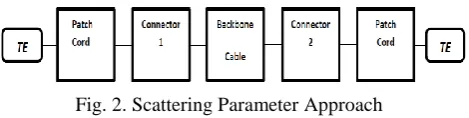
Fig. 2. Scattering Parameter Approach
The cable asymptotic impedance ( ) = 104.5 ohms, patch cord asymptotic impedance ( ) = 95.5 ohmsand asymptotic impedance of the test system ( ) =100 ohms as presented in [6].
To obtain the complex characteristics impedance as a function of frequency ,a heuristic impedance equation which has been proven extensively to describe very well the mean characteristics impedance values is stated in [1],[6] as:
[ √ ] (20) Therefore, the characteristics impedance of the cable and the
patch cords are given respectively as:
(21)
(22) The S-parameters of the cable and patch cords can be
individually determined using equation (2).
B. The Concatenation of Cables
This involves the concatenation of cables by converting their S-parameters into T-parameters and multiplying them sequentially as:
(23) The resultant T-parameters from equation (23) are then converted into S-parameters to obtain the insertion loss using equation (13).This method was applied to obtain the insertion loss for four different concatenations of cables: two 15m, three 8m, four 7m and five 6m cables. The cables were simulated at an asymptotic characteristics impedance of 104.5 ohms.
C. Connector and Insertion Loss Deviation Modeling
The connectors and insertion loss deviation were modeled by the attenuation constant that provided good agreement with the 40GBASE-T system. The attenuation constant was determined from the connecting hardware and insertion loss deviation for channel specifications with some modifications as:
( √ √ )
0.1 (24) [ √
√ ]
(25)
Equations (21) and (22) can be simplified as:
√ (26) √
[image:2.595.54.279.372.413.2](26) The T-parameters obtained from equation (26) is then
converted back to S-parameters. The S-parameters obtained from the conversion can be used to determine the insertion loss in decibels using equation (13).
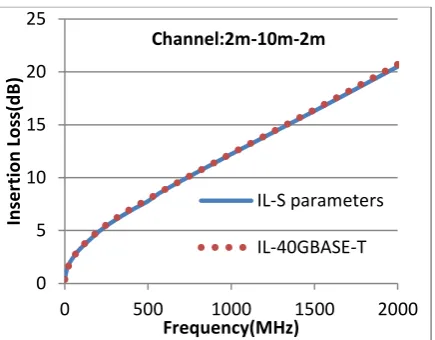
The insertion loss is simulated in MATLAB and compared with the insertion loss generated from the proposed category 8 cabling specifications stated in section II. This method of concatenation was applied to determine the insertion loss of the following channels: 3m-24m-3m, 1m-3m-1m, 2m-10m-2m, 1m-24m-5m, 0.5m-3m-0.5m and 1m-26m-3m.
IV. RESULTS AND DISCUSSION
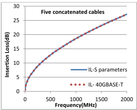
[image:3.595.314.541.46.218.2]The research provided insertion loss predictions for four different cable concatenations of two 15m, three 8m, four 7m and five 6m cables as presented in Fig. 3 to 6.The results show good agreement with the 40GBASE-T specified insertion loss specification. Similarly, the insertion loss prediction plots for different channels are shown in Fig.7 to 12.The simulation provided insertion loss prediction of 35.3418 decibels as against 35.5618 decibels generated from the channel specifications for 3m-24m-3m configurations at 2000MHz.The simulation procedure can be extended to simulate and observe other cable parameters behavior.
[image:3.595.312.538.266.440.2]Fig. 3. Insertion loss for two 15m cables
Fig. 4. Insertion loss for three 8m cables
Fig. 5. Insertion loss for four 7m cables
Fig. 6. Insertion loss for five 6m cables
0 5 10 15 20 25 30
0 500 1000 1500 2000
In
ser
tion
Loss(d
B
)
Frequency(MHz) Two concatenated cables
IL-S parameters
IL- 40GBASE-T
0 5 10 15 20 25
0 500 1000 1500 2000
In
ser
tion
Loss(d
B
)
Frequency(MHz) Three concatenated cables
IL-S parameters
IL- 40GBASE-T
0 5 10 15 20 25 30
0 500 1000 1500 2000
In
ser
tion
Loss(d
B
)
Frequency(MHz) Four concatenated cables
IL-S parameters
IL- 40GBASE-T
0 5 10 15 20 25 30
0 500 1000 1500 2000
In
ser
tion
Loss(d
B
)
Frequency(MHz) Five concatenated cables
IL-S parameters
[image:3.595.57.288.387.560.2] [image:3.595.313.537.485.665.2]Fig. 7. Insertion Loss for 3m-24m-3m channel
Fig. 8. Insertion loss for 1m-3m-1m channel
[image:4.595.313.534.268.432.2]Fig. 9. Insertion loss for 2m-10m-2m channel
[image:4.595.58.276.268.432.2]Fig. 10. Insertion loss for 1m-24m-5m channel
Fig. 11. Insertion loss for 0.5m-3m-0.5m channel
Fig. 12. Insertion loss for 1m-26m-3m channel
0 5 10 15 20 25 30 35 40
0 500 1000 1500 2000
In
ser
tion
Loss(d
B
)
Frequency(MHz) Channel:3m-24m-3m
IL-S parameters
IL-40GBASE-T
0 2 4 6 8 10 12 14
0 500 1000 1500 2000
In
se
rt
io
n
Lo
ss(
d
B
)
Frequency(MHz) Channel:1m-3m-1m
IL-S parameters
IL-40GBASE-T
0 5 10 15 20 25
0 500 1000 1500 2000
In
ser
tion
Loss(d
B
)
Frequency(MHz) Channel:2m-10m-2m
IL-S parameters
IL-40GBASE-T
0 5 10 15 20 25 30 35 40
0 500 1000 1500 2000
In
ser
tion
Loss(d
B
)
Frequency(MHz) Channel: 1m-24m-5m
IL-S parameters
IL-40GBASE-T
0.0 2.0 4.0 6.0 8.0 10.0 12.0
0 500 1000 1500 2000
Inser
ti
on
Loss
(d
B
)
Frequency(MHz) Channel:0.5m-3m-0.5m
IL-S parameters
IL- 40GBASE-T
0 5 10 15 20 25 30 35 40
0 500 1000 1500 2000
In
ser
tion
Loss(d
B
)
Frequency(MHz) Channel: 1m-26m-3m
IL-S parameters
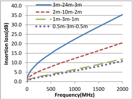
[image:4.595.58.276.479.649.2] [image:4.595.313.542.480.651.2]Fig. 13. Channel Insertion Loss Comparison
V. CONCLUSION
The paper has provided the scattering parameter approach to predict the insertion loss for the proposed category 8 cabling with two connectors in support of 40GBASE-T. The predictions by the scattering parameter show good agreement with all the channels considered. A comparison of the insertion loss for the channels indicates that the insertion loss increases with length and frequency.
The procedure can be extended to predict the insertion loss of other cable behavior necessary for the 40GBASE-T systems.
REFERENCES
[1] J. H. Walling, A .Duffy, “The Modeling of 4 Pair Data Grade Channels with the Aim to Use the Differential Mode Transmission Parameters which are given in the Standardized Specification Requirements”, 57th International Wire and Cable Symposium, Rhode Island, USA, November 9-12, 2008, pp.532-540.
[2] R.Papazyan, P.Petterson etal., “Extraction of High Frequency Power Cable Characteristics from S-parameters Measurements”, IEEE Transactions on Dielectrics and Electrical Insulation, Vol.II, No.3, June 2004, pp.461-470.
[3] H. Pandya, “The road to 40GBase-T in data center networks”, Electronics Products Magazine, Vol.21, No.9, September 2013, pp.31-34.
[4] F. Straka, “40 Gbits/s over twisted-pair copper cable is on the way”, Electronics Products Magazine, Vol.56, No.4, September 2013, pp.20-22.
[5] J.A.Dobrowolski,“Microwave Network Design Using the Scattering Matrix”, published by Artech House, 1981, pp.25-43.
[6] P.Kish,“Channel Return loss Modeling Results”, June 2013. Available:
http://www.ieee802.org/3/bq/public/channelmodeling/Channel_Return_ Loss_Modeling_Results_3.pdf).
[7] C. DiMinico, “40GBASE-T PHY-Channel Insertion Loss”, July 2013. Available:
(http://www.ieee802.org/3/bq/public/jul13/diminico_3bq_01_0713.pdf).
0.0 5.0 10.0 15.0 20.0 25.0 30.0 35.0 40.0
0 500 1000 1500 2000
Inser
ti
on
loss(dB
)