Abstract— The novel idea of a modified trilateral flash cycle with ejector has been proposed and called the ejector trilateral flash cycle (ETFC). The ETFC offers the advantage of being able to generate power by turbine expansion from saturated liquid as opposed to organic Rankine cyle (ORC) and partially evaporating cycle (PEC) which generates power by turbine expansion from saturated vapor and liquid-vapor mixture, respectively. In ETFC, the working fluid only needs to be heated up to saturated liquid state, which only requires sensible heating; whereas, ORC and PEC involve latent heating which requires significantly larger amount of heat. The thermal matching of ETFC to a sensible heat source is better than those of the ORC and the PEC. This makes ETFC ideal for applications of conversion of low-grade waste heat to power.
There are various commercial and industrial processes that produce heat as a by-product, only to discharge heat to the environment as waste. This waste heat contains significant amount of thermal energy that could be utilized for practical purposes.
In this paper, a mathematical model is developed for the ETFC using 1-dimensional irreversible adiabatic flow incorporated with friction. As a basis of calculation, the waste heat rejected from the condenser of an ice plant using ammonia was arbitrarily selected as the heat source. The heat rejected from an ice plant is significantly low-grade relative to other industrial plants such as cement plants, steel plants, power plants, etc.
The developed model is used in simulating the ETFC system for 44 working fluids to determine the optimized performance, ejector geometries, and thermodynamic parameters for the system. Properties of fluid at each state points of the cycle were determined. Only 22 out of the 44 fluids resulted in an increase in net work. From the 22 fluids, RC318 had the highest increase in net work at 6.14% increase from the conventional TFC. RC318 also has the highest power generation potential at 53 kW at an exergy efficiency of 9.87%.
Index Terms— ejector, modeling, triangle cycle, trilateral flash cycle, waste heat
Manuscript received March 14, 2017; revised April 9, 2017. The dissemination of this research is sponsored by the Engineering Research and Development Program (ERDT) of the Department of Science and Technology (DOST) of the Republic of the Philippines. The program is being managed and implemented by the College of Engineering of University of the Philippines–Diliman.
C. B. Co is an M.S. Energy Engineering student from the University of the Philippines – Diliman, Quezon City, 1101 Philippines (phone: +63-917-656-5508; e-mail: [email protected]).
M. S. Berana is with the Department of Mechanical Engineering, College of Engineering, University of the Philippines – Diliman, Quezon City, 1101 Philippines (phone: +63-906-214-1782, +63-2-981-8500 loc 3130; fax: +63-2-709-8786; e-mail: [email protected]).
I. INTRODUCTION
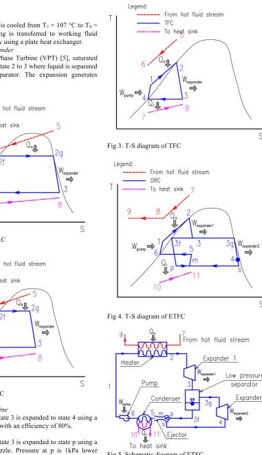
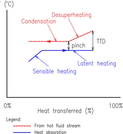
here are various commercial and industrial processes that produce heat as a by-product only to discharge the heat to the environment as waste. This waste heat contains significant amount of thermal energy that could be utilized for practical purposes by recovering the heat and converting thermal energy into electrical energy [1]. The organic Rankine cycle (ORC), partially evaporating cycle (PEC), and trilateral flash cycle (TFC), as illustrated in Fig 1, 2, and 3 respectively, are some known power cycles that can be powered by low-grade heat. Compared to the ORC and PEC, the TFC has the advantage of being able to generate power by turbine expansion from saturated liquid as opposed to ORC’s and PEC’s turbine expansion from saturated vapor and liquid-vapor mixture, respectively [2], [3], and [4]. In TFC, the working fluid only needs to be heated up to saturated liquid state, which only requires sensible heating; whereas, ORC and PEC involves latent heating which requires significantly larger amount of heat compared to a sensible one. The TFC also involves better thermal matching than either ORC and PEC as illustrated in Fig 6 and 7. This makes TFC ideal for conversion from low-grade heat to power. As a basis of calculation, the waste heat rejected from the condenser of an ice plant using ammonia was arbitrarily selected as the heat source. The heat rejected from an ice plant is significantly low-grade relative to other industrial plants such as cement plants, steel plants, power plants, etc. If the ETFC proves to be viable using a low grade heat source as low as that of an ice plant, the range of viable heat source temperature is widened and it can strengthen the confidence in using low grade heat sources.
The ETFC, shown in Fig 4 and 5, is not like any other power cycle. Although it is a modification of the conventional TFC, its operating principle is more similar to a combined cycle power plant where TFC is the topping cycle and the ORC is the bottoming cycle. All expansion processes: the liquid dominated expansion and the vapor dominated expansion, are both generating power. Because of the ejector, the turbine expansion can be expanded to a pressure lower than the condenser pressure thus increasing the turbine work output.
The critical component of the ETFC is the ejector. The ejector must be carefully modelled with the optimum geometry that will recover the pressure and give a significant increase in the overall cycle efficiency.
Modelling
and Analysis of Power Generation
from Low Grade Industrial Waste Heat Using
Ejector
Trilateral Flash Cycle
Celden B. Co and Menandro S. Berana
II. ENERGY CONVERSION OF ETFC All labels of each of the state points in the ETFC are indicated in Fig 4 and 5.
A. Heat absorption
Superheated ammonia is cooled from T7 = 107 °C to T9 = 38 °C. Heat from cooling is transferred to working fluid from T1 to T2 = 106 °C by using a plate heat exchanger. B. Liquid dominated expander
[image:2.595.149.531.82.744.2]By using a Variable Phase Turbine (VPT) [5], saturated liquid is expanded from state 2 to 3 where liquid is separated from vapor using a separator. The expansion generates power at 70% efficiency.
[image:2.595.50.280.217.650.2]Fig 1. T-S diagram of ORC
Fig 2. T-S diagram of PEC C. Vapor dominated turbine
The vapor portion of state 3 is expanded to state 4 using a vapor dominated turbine with an efficiency of 80%.
D. Ejector modelling
The liquid portion of state 3 is expanded to state p using a converging-diverging nozzle. Pressure at p is 1kPa lower than Pressure at state 4. The 1 kPa pressure difference will cause an entrainment effect and the two fluids will be mixed in the mixing section of the ejector. The mixture will then be re-pressurized back to the condenser pressure at state 5.
Detailed modeling of the ejector, see Fig 8, will be discussed in part III.
Fig 3. T-S diagram of TFC
Fig 4. T-S diagram of ETFC
Fig 5. Schematic diagram of ETFC E. Condenser
[image:2.595.53.275.436.645.2]to 6, evaporative condenser was used in order to take advantage of the wet bulb temperature = 28 °C as a design parameter instead of the dry bulb temperature = 33 °C. F. Pump
Saturated liquid at state 6 is pumped to a higher pressure at state 1 which will close the cycle and start it all over again.
G. Working fluids
All 121 fluids listed in REFPROP version 9.1 [9] were considered in this study. Critical point and minimum operating pressure were used as the initial screening criteria to rule out fluids that do not fit the thermodynamic requirements of the ETFC.
Fig 6. Temperature matching when latent heat is involved
Fig 7. Temperature matching when only sensible heat is involved
III. NUMERICAL MODEL A. Primary Nozzle
The liquid portion of state 3 enters the primary nozzle of the ejector at high pressure and temperature but with
negligible velocity. The primary nozzle is basically a converging-diverging nozzle. Berana et al discussed this in detail in their studies [6, 7]. It is assumed that the inlet properties of the fluid is at state i are all known. In order to determine the properties at state o after an increment distance ΔL corresponding to a set uniform ΔT, the conservation equations and thermodynamic relations are applied. Specifically, the properties of the refrigerant entering the nozzle are known (Pi, Ti, hi, si, vi, µi, Ui and Ai). In order to get the values in state 2 (Po, To, ho, so, vo, µo, Uo and Ao), conservation equations for mass, energy and momentum were applied together. The aforementioned equations are applied successively for every given distance until the exit of the nozzle is reached. The properties of the determined state points in the iteration are calculated using Maruo Editor [8] and the REFPROP thermodynamic database of the NIST [9].
For adiabatic process:
𝑞!"=0 (1)
Conservation of Mass: !!!!
!! = !!!!
!! (2) Conservation of Energy:
−𝑑ℎ=𝑑 !!
! (3) Conservation of Momentum:
−𝑣!" !"=
! !"
!! ! +2𝑓
!!
! (4) The Blasius-type friction factor was used in the analysis of ejector as expressed by the equation
𝑓=𝐶𝑅𝑒!! (5)
For the range of 3050 to 240,000 of Reynolds number, the value of C is 0.351 and n is equal to 0.225. But, for Re value of 240,000 and above, C is 0.118 and n is equal to 0.165, from the study of Joseph and Yang [10].
Velocity and area in the state 2 was calculated by using (6) and (7), respectively.
𝑈! = 𝑈!!+2 ℎ
!−ℎ! (6)
𝐴! =𝐴!!!
!! !!
!! (7) The length of the controlled element for the converging and diverging section was calculated by using (8) and (9), respectively.
𝐿=
!! !! !!
!!
!! !!
!!"#!! (8)
𝐿=!! !!!
!!
!!
!! !!
[image:3.595.53.256.219.440.2]B. Pre-mixing Section
The pre-mixing section is the portion comprised of the exit plane of the primary nozzle, the inlet plane of the secondary fluid and the inlet plane of the constant-area mixing section. The pre-mixing section was set apart from the mixing chamber to model and analyze separately the processes involved in each flow of the working fluid in order to determine the geometry of the ejector. In the pre-mixing section, there are no interactions or pre-mixing of flow between the primary and the secondary fluids, making the analysis of each simpler and more accurate.
The primary fluid from the nozzle and the secondary fluid draw toward a plane in the inlet of the mixing section. The two fluids have different velocities, the primary being supersonic, while the secondary being subsonic, so there forms a shear layer separating them. This “barrier” gradually becomes thinner until the fluids reach the inlet of the mixing chamber where they start to mix. It should be noted though that the mixing would only happen when the two fluids reach equal pressure and the Mach number of the secondary fluid is equal to unity. The analysis of the controlled element in the primary and secondary flows is similar to the analysis used in the converging-diverging nozzle.
C. Mixing Section
The cylindrical-shaped component of the ejector with a constant-area is the mixing section. It is where the primary and secondary fluids start to interact, then fully mix and become a homogenous fluid flowing towards the inlet of the diffuser. Several thermodynamic processes arise during the mixing process. However, in this study, the main concern is to characterize the flow of the fluid before and after the mixing only.
The diameter of the mixing section is assumed to be 10 times of the nozzle throat diameter to achieve the probability that the primary and the secondary flow mix at a constant pressure.
The velocity and quality of the fully mixed fluid in the mixing section is expressed by (10) and (11).
𝑈!=
!!!!"!!!"!!!!!!!"!!!"!!!!!!!"#
!!!!! (10)
𝑥!=! !
!",! !!
!!!!! ℎ!,!+𝑥!"ℎ!",! + !!"!
! +
!!
!!!!! ℎ!,!+𝑥!"ℎ!",! + !!"!
!
−!!! ! −ℎ!,!
[image:4.595.49.538.518.778.2](11)
Fig 8. Ejector diagram D. Diffuser
The diffuser of the ejector is responsible for compressing the fluid to the condenser pressure. The available kinetic energy at the diffuser inlet is used to elevate the pressure. Thus, the flow velocity decreases as the fluid passes through the diffuser. The analysis of the controlled element in the diffuser is similar to the analysis used in the diverging nozzle except that the temperature in the simulation is incremented in this case.
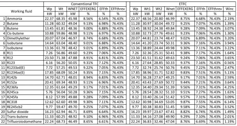
TABLE I
IV. RESULTS AND DISCUSSIONS
Out of the 44 fluids tested, only 22 resulted with an increase in Wnet. Table I shows all 22 fluids that resulted in a small but very significant increase in Wnet. It is expected that thermal efficiency is low especially when considering low temperature power cycles. Exergy efficiency is also very small due to the large difference between thermal efficiency and reversible thermal efficiency. The criteria for optimization used in this study is the Winc and Wnet.
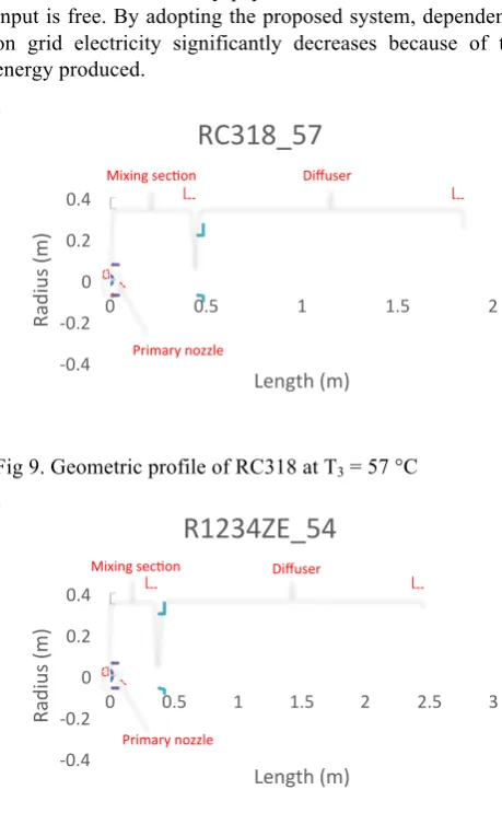
The geometry of the ejectors of the top 3 fluids based on Winc and Wnet are shown in Fig 9, 10, and 11. To compensate for the difficulty of re-pressurization from vacuum, aesthetics have been compromised. A long ejector and wide diffuser outlet diameter is needed for an effective pressure recovery. The geometrical ratio of RC318, R1234ze, and R236fa, presented in Fig 9, 10, and 11 respectively are similar with the other 19 fluids.
[image:5.595.308.538.356.728.2]The optimum thermodynamic parameters for each state points of the ETFC have been calculated and presented in Table II.
TABLE II
THERMODYNAMIC PARAMETERS OF TOP 3 WORKING FLUIDS
V. CONCLUSION
A mathematical model is developed for the ETFC. The ejector was modelled using 1-dimensional irreversible adiabatic flow incorporated with friction. The developed model is used in simulating the ETFC for 44 fluids. Only 22 out of the 44 fluids resulted in an increase in net work. From the 22 fluids, RC318 had the highest increase in net work at 6.14% increase from the conventional TFC. RC318 also has the highest power generation potential at 53 kW at an exergy efficiency of 9.87%.
Although both thermal and exergy efficiencies are low, All 22 fluids proved to be effective working fluids for ETFC. It is expected with low temp power cycles to have low efficiencies. The thermodynamic inefficiency of ETFC is compensated by the savings from the power produces which can either be consumed by the ice plant of be fed back to the grid.
[image:5.595.86.262.390.721.2]When waste heat is produced as a by-product, the ETFC is an ideal addition to the system installed either during construction of the system or as a retrofit installation. From a “waste heat recovery to power conversion” point of view, the ETFC will essentially pay for itself because the energy input is free. By adopting the proposed system, dependence on grid electricity significantly decreases because of the energy produced.
Fig 9. Geometric profile of RC318 at T3 = 57 °C
Fig 10. Geometric profile of RC1234ze at T3 = 54 °C
-0.4 -0.2 0 0.2 0.4
0 0.5 1 1.5 2
Radius (m)
Length (m)
RC318_57
Mixing secAon DiffuserPrimary nozzle
-0.4 -0.2 0 0.2 0.4
0 0.5 1 1.5 2 2.5 3
Radius (m)
Length (m)
R1234ZE_54
Mixing secAon Diffuser [image:5.595.310.536.409.547.2]Fig 11. Geometric profile of R236fa at T3 = 53 °C
ACKNOWLEDGMENT
The authors are sincerely thankful to the Engineering Research and Development for Technology (ERDT) Program of the Department of Science and Technology – Science Education Institute (DOST – SEI) of the Republic of the Philippines for funding this research and its dissemination.
NOMENCLATURE
A cross sectional area (m2) C Blasius friction-type factor coefficient (-)
COP coefficient of performance (-) D hydraulic diameter (m)
ER entrainment ratio (-) f homogeneous friction factor (-) h enthalpy (J/kg)
KE kinetic energy (m2/s2) L length (m)
𝑚 mass flow rate (kg/s) n Blasius index (-)
P pressure (Pa) T temperature (°C) Q heat (W) RE Reynolds number (-) s entropy (J/kgK)
U velocity (m/s) v specific volume (m3/kg)
x quality (-) z flow axis (m) W work (kW)
EFF efficiency (%)
Greek
θ
angle (°) η efficiency (-) Subscriptsi inlet, state point o outlet, state point
boiler state in the boiler c converging cv control volume d diverging
diff state in the diffuser irr irreversible
isen isentropic
m average/mean value
mixing state in the mixing section
nozzle state in the nozzle p primary flow
pump state in the pump
py primary flow at the inlet of mixing chamber s secondary flow; constant entropy se secondary fluid expansion
sy secondary flow at the inlet of mixing chamber
y mixing section inlet
1 to 10 state points from state 1 to 10
turbine turbine
expander expander
net net (output minus input)
inc increase
EXERG exergy th thermal
threv reversible thermal
REFERENCES
[1] B. F. Tchanche, G. Lambrinos, A. Frangoudakis, G. Papadakis, “Low-grade heat conversion into power using organic Rankine cycles – A review of various applications,” Renewable and sustainable energy reviews 15, 2011, 3963-3979.
[2] J. Fischer, “Comparison of trilateral cycles and organic Rankine cycles,” Energy 36(10), 2011, 6208-6219.
[3] N. A. Lai, and J. Fischer, “Efficiencies of power flash cycles,” Energy 44(1), 2012, 1017-1027.
[4] M. Steffen, M. Löffler, K. Schaber, “Efficiency of a new triangle cycle with flash evaporation in a piston engine,” Energy 57, 2013 295-307.
[5] P. Welch, P. Boyle, “New turbines to enable efficient geothermal power plants,” Geothermal resource council transactions 33, 2009, 765-772.
[6] M. S. Berana, “Ejector power plant system with natural working fluid,” Philippine Engineering Journal Vol 34, No. 1, 2013
[7] M. S. Berana, E. T. Bermido, “Design of converging-diverging nozzle of an ejector for power plant applications using natural working fluids,” Proceedings of the sustainable future energy Conference, Brunei Darussalam, 2012
[8] K. Saitou, Maruo Editor Version 7.07, 2007
[9] E. W. Lemmon, M. O. McLinden, M. L. Huber, NIST Standard Reference Database 23: Reference Fluid Thermodynamic and Transport Properties-REFPROP, Version 9.1, National Institute of Standards and Technology (NIST), Gaithersburg, Maryland, 2013. [10] D.D. Joseph, B.H. Yang, “Friction factor correlations for laminar,
transition and turbulent flow in smooth pipes,” Physica D: Nonlinear Phenomena, Vol. 239, 2010, 1318-1328.
[11] ASHRAE standard: Designation and safety classifications of refrigerants, 2000
-0.4 -0.2 0 0.2 0.4
0 0.5 1 1.5 2
Radius (m)
Length (m)