Spatial dopant profiles for transverse-mode
selection in multimode waveguides
Tajamal Bhutta, Jacob I. Mackenzie, and David P. Shepherd
Optoelectronics Research Centre, University of Southampton, Highfield, Southampton SO17 1BJ, UK
Raymond J. Beach
Maxios Laser Corporation, 4749-A Bennett Drive, Livermore, California 94550
Received September 25, 2001; revised manuscript received January 7, 2001
We theoretically investigated the effect of the spatial distribution of the active-ion concentration in multimode step-index waveguides on transverse-mode selection for continuous-wave laser operation. We found that uni-form doping of a central portion of as much as 60% of the full waveguide core width is highly effective for the selection of fundamental-mode operation, even under highly saturated, high-power conditions. Profiling the dopant distribution to match that of the particular mode desired was also found to be effective, especially if it is the saturated inversion profile that is matched to the shape of the mode. © 2002 Optical Society of America
OCIS codes: 140.3430, 140.3460, 130.2790.
1. INTRODUCTION
There is a growing interest in the use of guided-wave ge-ometries for high-power laser operation, in both fiber1,2 and planar3,4 formats. The use of high-power diode pump lasers requires multimode waveguides for the con-finement of these non-diffraction-limited light sources, but most applications require fundamental-mode laser operation. In optical fibers this type of operation can be achieved by use of cladding-pumping techniques5 such that the pump and the laser signals are guided by differ-ent, but spatially overlapping, waveguides. However, it is hard to apply such a technique to planar geometry be-cause of the associated large increase in length required for absorbing the pump. Even in a fiber geometry, energy storage, power handling, and avoidance of nonlinear ef-fects can lead to a desire for large-mode-area,6and hence multimode, waveguides. One technique that has been used to select fundamental-mode operation from multi-mode waveguides is to limit the doping region to a central portion of the waveguide to give a preferential overlap with the fundamental mode.6,7 Here we theoretically in-vestigate how tailoring the doping profile in this way can lead to the required modal discrimination in continuous-wave lasers, and we investigate the effects of gain satu-ration, which itself varies spatially, on this selectivity. We show that, even under highly saturated, high-power conditions, fundamental-mode operation can be robustly selected, and we compare our results with reported ex-perimental data. It is also found that, if desired, indi-vidual high-order modes can be preferentially selected through tailoring of the dopant profile and that we can ob-tain higher modal discrimination by accounting for the change in the gain distribution that is due to saturation by the lasing mode.
The model presented at the beginning of this paper is based on the analysis of Risk8and can be applied to many
situations including planar, fiber, and bulk geometries. Thereafter we shall concentrate on planar waveguides with doping profiles that vary in just one dimension. This simplest of cases corresponds directly to our study of double-clad YAG waveguide lasers3,7,9and also brings out features that are common to many geometries.
2. THEORY
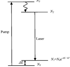
Let us assume a quasi-three-level laser transition and an energy-level diagram and population densities as defined by Risk;8 see Fig. 1. We shall continue to follow the analysis of Risk8 but will modify it to allow for a trans-verse spatial variation in the doping concentration. We also assume a uniform pump distribution owing to the highly multimode nature of the waveguide and the high-power diode pump source. The rate equation for the population inversion density,⌬N(x, y,z), assuming neg-ligible ground-state depletion, is then
d⌬N共x,y, z兲
dt ⫽fRd共x,y, z兲
⫺ ⌬N共x, y, z兲⫹ n1
0d共x,y, z兲
⫺ fc⌬N共x, y,z兲
n ⌽共x, y, z兲⫽0,
(1) wheref ⫽f1⫹f2(see Fig. 1),is the lifetime of the
up-per laser-level manifold, cis the speed of light, andis the gain cross section. The rate at which ions are pumped into the upper laser manifold is given by R ⫽Pa/hvp, wherePais the absorbed pump power andvp
is the pump frequency. The unpumped population den-sity in the lower laser level is given by n10d(x, y, z),
wheren10 is the total population in the unpumped lower
laser level andd(x,y, z) is the dopant profile normalized such that
冕冕冕
d共x, y,z兲dV ⫽1. (2)The total number of laser photons in the cavity is given by
⌽ ⫽2nlPl/chvl, where Pl is the one-directional
intra-cavity laser power in the waveguide,nis the refractive in-dex, l is the length of the cavity, andvl is the laser
fre-quency. The spatial distribution of the photons,
(x,y, z), is normalized such that
冕冕冕
共x,y, z兲dV ⫽1. (3)From Eq. (1) we can see that below threshold (⌽⫽0) the inversion has the same spatial distribution as the doping and the ground-state population (which does not change in shape owing to our assumption of negligible ground-state depletion). As was shown by Risk,8 at threshold and above, the inversion averaged over the
laser-mode profile becomes clamped at the threshold value such that
冕冕冕
⌬N共x,y, z兲共x, y, z兲dV⫽ L⫹T2l , (4)
whereLis the round-trip loss andTis the transmission of the output coupler. However, the spatial distribution of
the inversion above threshold will change as a result of saturation by the lasing photons. From Eq. (1) it can be seen that, above threshold,
⌬N共x,y, z兲 ⫽ fRd共x,y, z兲 ⫺n1
0d共x, y, z兲
1⫹ c
n f⌽共x,y, z兲
. (5)
We can combine Eqs. (4) and (5) to find the population in-version distribution expressed only in terms of the losses and the laser power:
whereS⫽ 2flPl/hvl gives a measure of the degree of
saturation caused by the intracavity laser power. The gain exponent,Gp, for a particular mode with spatial
dis-tributionp, with a population inversion saturated by a lasing mode with spatial distribution, is then given by
Gp⫽2l
冕冕冕
⌬N共x,y, z兲p共x, y, z兲dV. (7)Equations (6) and (7) can now be combined to give the gain for each mode,gfp, relative to the lasing mode,:
Equation (8) can be evaluated to give the relative gain for each waveguide mode for a given dopant distribution, saturating distribution, and saturating power. It should be noted that, as a direct result of the uniform pumping distribution in a highly multimode waveguide, this selec-tivity is independent of n10, and thus the same results
will be obtained for four-level and quasi-three-level la-sers.
3. ONE-DIMENSIONAL STEP-FUNCTION
DOPING DISTRIBUTION
Experimental work in planar,3,7,9 fiber,2,6 and bulk
[image:2.612.106.242.552.684.2]lasers10have used step-function dopant distributions re-stricted to a central region of the allowed modes, as this distribution is relatively easy in terms of fabrication. Figure 2 shows an example of a one-dimensional step-function doping profile together with the three lowest-order waveguide modes of a highly multimode, step-index waveguide of depthD. This one-dimensional example is taken as the simplest case for initial investigation. We now make the assumption that the modes are far from cutoff, as would be the case for most of the modes in a highly multimode waveguide, and we make the approxi-mation that they are fully confined within the core. The
Fig. 1. Energy-level diagram. N0–3are the population densi-ties of the Stark levels involved, such thatN2⫽f2NU andN1 ⫽ f1NL, whereNUandNL are the population densities of the upper and the lower laser level manifolds, respectively, andf1,2 are the fractional occupancies.
⌬N共x, y, z兲⫽ d共x, y,z兲共L⫹T兲
2l关1 ⫹S共x, y, z兲兴
冕冕冕
d共x, y, z兲共x,y, z兲 1 ⫹S共x,y, z兲 dV, (6)
Grel⫽
Gp
L⫹T ⫽
冕冕冕
d共x, y,z兲p
关1⫹ S共x, y,z兲兴
冋
冕冕冕
d共x, y,z兲共x,y, z兲 1 ⫹S共x,y, z兲 dV册
normalized spatial distribution of photons [Eq. (3)] for the even and odd modes is then given by11
even共x,y, z兲⫽ 2 WDLcos
2
冋
共m⫹1兲xD
册
, (9a)odd共x,y, z兲 ⫽ 2 WDLsin
2
冋
共m⫹1兲xD
册
, (9b)wheremis the mode number (m⫽ 0, 2, 4 ... for the even modes and m⫽ 1, 3, 5 ... for the odd modes), L is the length of the guide, andWis the width of the guide.
It can be seen from Fig. 2 that doping a fraction,r/D, of the core can lead to a preferential gain for the fundamen-tal mode. Applying Eqs. (9) and the step-function doping of Fig. 2 to Eq. (8) allows us to calculate the relative gain for each of the waveguide modes in this situation. Figure 3 shows the results of this calculation for the ten lowest-order modes and how the result varies with doping frac-tion for the case of no signal saturafrac-tion (i.e., at lasing threshold). For small doped fractions the gain becomes the same for all the even modes, as each of these modes has a central peak in its intensity profile, whereas the gain for the odd modes tends to zero as each of these modes has zero intensity at the center of its core. The gain for all the modes becomes equal for a fully doped core, showing that a normal multimode waveguide will in-deed suffer from multimode laser output. For
intermedi-ate doped fractions there is a clear gain advantage for the fundamental mode, implying that this mode will lase first.
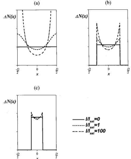
[image:3.612.86.268.54.180.2]However, once lasing occurs, the fundamental mode will start to saturate the inversion, altering its spatial profile in a way that may change the mode selectivity from that shown in Fig. 3. The saturation behavior for three different doped fractions owing to saturation by the fundamental mode is shown in Fig. 4. It can be seen that the change in shape of the inversion profile is much smaller for the smaller doping fractions. It is interesting to note that little change occurs in the saturation profile once the intensity of the laser beam reaches several times the saturation intensity.
Figure 5 shows the relative gain for the ten lowest-order waveguide modes under highly saturated conditions (I/Isat⫽ 100). It can be seen that, as expected, heavy
saturation can lead to the gain for the high-order modes’ becoming larger than that for the fundamental mode. It appears that it is always the lowest-order odd mode (m ⫽ 1) that is the first higher-order mode to oscillate. However, we can also see that there is still a window for doping fractions below 0.6 with a clear gain advantage for the fundamental mode. The result of Fig. 5 also remains virtually unchanged for even higher lasing powers, be-cause of the unchanging inversion profile at high satura-tion levels.
Figure 6 shows a plot of the doping fraction at which the gain for the m⫽ 1 mode becomes equal to that for them ⫽0 mode against the intracavity lasing intensity. Once again we can see that the fraction is virtually un-changing once the intensity is greater than a few times
[image:3.612.65.289.225.384.2]Fig. 2. Step-function doping of the central region of the core, and the three lowest-order propagation modes of the highly mul-timode waveguide.
[image:3.612.327.547.435.703.2]Fig. 3. Relative gain for the ten lowest-order modes relative to doping fraction forI/Isat⫽0, whereIis the intracavity lasing in-tensity andIsat⫽hv/is the saturation intensity.
[image:3.612.92.295.459.523.2]the saturation intensity. Thus, in practice, taking into consideration a desire not to increase the pump absorp-tion length too much indicates that a doping fracabsorp-tion of approximately 0.5 appears to be a good choice for robust fundamental mode selection at high laser powers. It should be noted that, once a higher-order mode starts to oscillate, Eq. (8) is no longer valid, as this new mode will also contribute to the saturation of the gain. However, in the study reported here we are interested only in the re-gime in which single transverse mode is oscillating.
There are some practical limitations on the use of this method. First, the active-ion doping normally brings with it a small change in refractive index. Therefore, at a certain doping width the refractive index will create its own waveguide rather than merely modifying the proper-ties of the highly multimode guide, and the mode-selecting properties will be lost. Second, for high-power operation the thermal loading of the doped region will also have an effect on the refractive index, which must be taken into consideration. The closest experimental work to the structure modeled here is that with diode-pumped double-clad YAG planar waveguides that have been oper-ated at high power (⬎10 W) for Nd, Yb, and Tm dopants.3,7,9 In those experiments doping fractions as great as 0.67 were found to give fundamental-mode opera-tion. The reason for this better-than-expected perfor-mance may be due to our initial assumption of an un-changing ground-state population. In reality, the regions
that are heavily saturated by the laser signal will have a correspondingly increased pump absorption as a result of the increased population in the ground level that will then act against the effects described above and aid in fundamental-mode selection. Thus it appears that our model may be a worst-case limit, which can be seen as a useful design feature. We have also assumed that the losses for all the modes are the same, which may not nec-essarily be the case.
4. ONE-DIMENSIONAL PROFILED DOPING
DISTRIBUTIONS
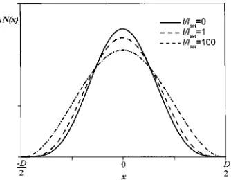
If the fabrication technique allows, higher selectivity can be obtained with a more-sophisticated doping profile. For instance, if we make a doping profile proportional to the square of the fundamental mode profile we find that the final saturated profile is still Gaussian-like, as shown in Fig. 7. Consequently, the mode selectivity of such a profile is very high, even for full doping fractions, as shown in Fig. 8.
[image:4.612.65.289.52.212.2]It should also be noted that it is not just the fundamen-tal mode that can be selected. For instance, similar cal-culations show that, by setting the doping profile to be the square of them⫽9 mode profile we can expect laser op-eration to occur robustly on this single higher-order mode.
[image:4.612.88.270.259.390.2]Fig. 5. Relative gain for the ten lowest-order modes relative to doping fraction for a heavily saturated gain region.
Fig. 6. Doping fraction at which high-order-mode oscillation oc-curs relative to value ofI/Isat.
Fig. 7. Spatial distribution of the inversion for various levels of saturation by the fundamental mode for an original doping pro-file that is the square of the fundamental-mode propro-file.
[image:4.612.357.524.358.488.2] [image:4.612.323.552.545.702.2]5. OTHER GEOMETRIES
The theory developed here, as expressed in Eq. (8), can certainly also be used to analyze modal discrimination of two-dimensional doping distributions. Practical ex-amples of such distributions include large-mode-area fiber2,6and bulk lasers with composite rods.10 However, the selectivity in a fiber will be compromised by the fact that, because of bending, there is always a certain degree of coupling between the propagation modes. For the case of a bulk laser it should be noted that the selectivity is be-tween the modes of the resonator rather than bebe-tween the propagation modes of a waveguide.
6. SUMMARY
We have used a rate-equation approach to find the transverse-mode discrimination that can be obtained in a continuous-wave laser by spatially varying the active-ion dopant distribution. For a highly multimode waveguide pumped by a high-power diode bar, which permits the as-sumption of a uniform pump distribution, we find that re-stricting the doping to a central portion (⬍60%) of the core can be used to robustly select fundamental-mode op-eration, even for highly saturated, high-power operation. For higher doping fractions, multimode operation will oc-cur. We also find that profiling the dopant distribution such that the saturated inversion profile matches the shape of the particular transverse-mode desired also gives a high modal discrimination, whether it is for the fundamental mode or for a higher-order mode.
ACKNOWLEDGMENTS
The authors acknowledge support from UK Engineering and Physical Sciences Research Council (EPSRC) grant GR/M98449/01. Tajamal Bhutta acknowledges support from an EPSRC studentship and from Onyx Optics, Inc.
D. P. Shepherd’s e-mail address is [email protected].
REFERENCES
1. V. Dominic, S. MacCormack, R. Waarts, S. Sanders, S. Bicknese, R. Dohle, E. Wolak, P. S. Yeh, and E. Zucker, ‘‘110W fibre laser,’’ Electron. Lett.35, 1158–1160 (1999). 2. J. A. Alvarez-Chavez, H. L. Offerhaus, J. Nilsson, P. W.
Turner, W. A. Clarkson, and D. J. Richardson, ‘‘High-energy, high-power, ytterbium-doped Q-switched fiber laser,’’ Opt. Lett.25, 37–39 (2000).
3. R. J. Beach, S. C. Mitchell, H. E. Meissner, O. R. Meissner, W. F. Krupke, J. M. McMahon, W. J. Bennett, and D. P. Shepherd, ‘‘Continuous-wave and passively Q-switched cladding-pumped planar waveguide devices,’’ Opt. Lett.26, 881–883 (2001).
4. J. R. Lee, G. J. Friel, H. J. Baker, G. J. Hilton, and D. R. Hall, ‘‘A Nd:YAG planar waveguide laser operated at 121 W output with face pumping by diode bars, and its use as a power amplifier,’’ inAdvanced Solid State Lasers, Vol. 50 of OSA Trends in Optics and Photonics Series (Optical Society of America, Washington, D.C., 2001), paper TuC3-1. 5. E. Snitzer, H. Po, F. Hakimi, R. Tumminelli, and B. C.
Mc-Collum, ‘‘Double-clad, offset core Nd fiber laser,’’ inOptical Fiber Communication, Vol. 1 of 1988 OSA Technical Digest Series (Optical Society of America, Washington, D.C., 1988), paper PD5.
6. H. L. Offerhaus, N. G. Broderick, D. J. Richardson, R. Sam-mut, J. Caplen, and L. Dong, ‘‘High-energy single-transverse-mode Q-switched fiber laser based on a multi-mode large-multi-mode-area erbium-doped fiber,’’ Opt. Lett. 23, 1683–1685 (1998).
7. C. L. Bonner, T. Bhutta, D. P. Shepherd, and A. C. Tropper, ‘‘Double-clad structures and proximity coupling for diode-bar-pumped planar waveguide lasers,’’ IEEE J. Quantum Electron.36, 236–242 (2000).
8. W. P. Risk, ‘‘Modeling of longitudinally pumped solid-state lasers exhibiting reabsorption losses,’’ J. Opt. Soc. Am. B5, 1412–1423 (1988).
9. J. I. Mackenzie, S. C. Mitchell, R. J. Beach, H. E. Meissner, and D. P. Shepherd, ‘‘15 W diode-side-pumped Tm:YAG waveguide laser at 2 m,’’ Electron. Lett. 37, 898–899 (2001).
10. A. Lucianetti, R. Weber, W. Hodel, H. P. Weber, A. Papash-vili, V. A. Konyushkin, and T. T. Basiev, ‘‘Beam-quality im-provement of a passivelyQ-switched Nd:YAG laser with a core-doped rod,’’ Appl. Opt.38, 1777–1783 (1999).