Abstract— A minimum-time problem on deceleration of rotations of a free rigid body is studied. It is assumed that the body contains a spherical cavity filled with highly viscous fluid. The body is subjected to a retarding torque of viscous friction. It is assumed that the body is dynamically asymmetric. An optimal control law for the deceleration of rotations of the body is synthesized, and the corresponding time and phase trajectories are determined.
Index Terms—optimal deceleration, resistive medium, asymmetric rigid body, cavity filled with viscous fluid
I. INTRODUCTION
NALYSIS of the motion of hybrid systems (i.e., objects containing elements with distributed and concentrated parameters) is of interest both theoretically and practically. This analysis can be done within the framework of the theory of singularly perturbed problems. Important results were obtained for systems containing quasi-rigid bodies. Combined rotational and translational motions of these systems are close (under certain conditions) to the motion of absolutely rigid bodies. The influence of non-ideal features are reduced to the effects of the temporal boundary layer type and to additional perturbing moments in the Euler equations of angular motion of a fictitious rigid body after the completion of transient processes. The analysis of motions of a rigid body with a cavity filled with a viscous fluid and in a resistive medium had received much attention [1–6]. The control of rotations of quasi-rigid bodies using concentrated (applied to the frame) torques received less attention. Researchers managed to distinguish a class of systems leading to smooth controls making it possible to apply singular disturbance methods without accumulation of boundary layer type errors appearing in the case of discontinuous (for example, bang-bang) controls [7–9]. In Manuscript received July 14, 2013. This work was supported in part by the project №Ф53.1/010 by the third joint competition of the State Fund for Fundamental Research of Ukraine and Russian Foundation for Basic Research 2013.
L. D. Akulenko is with Ishlinsky Institute for Problems in Mechanics, Russian Academy of Sciences, Moscow 119526, Russia (e-mail: [email protected]).
D. D. Leshchenko is with Odessa State Academy of Civil Engineering and Architecture, Odessa 65029, Ukraine (corresponding author to provide phone: +38(048)7206-849; e-mail: [email protected]).
A. L. Rachinskaya is with Mechnikov Odessa National University, Odessa 65026, Ukraine (e-mail: [email protected]).
I. S. Zinkevych is with Odessa State Academy of Civil Engineering and Architecture, Odessa 65029, Ukraine (e-mail: [email protected]).
this paper, we investigate the problem of time-optimal deceleration of rotations of a dynamically nonsymmetric body with a spherical cavity filled with highly viscous fluid (for small Reynolds numbers). In addition, the rigid body is subjected to the action of a small retarding torque of linear resistance of the medium. The rotations are controlled by a bounded torque, which can be exerted by vernier jet engines [7]. The model under consideration generalizes the results obtained earlier in [7–11]. The problem of optimal deceleration of rotations of a dynamically symmetric body containing a viscous–elastic element and a cavity filled with fluid is studied in [8]. The problem of time-optimal deceleration of rotations of a dynamically symmetric rigid body with a spherical cavity filled with highly viscous fluid and a moving mass attached to the body by an elastic joint with quadratic dissipation is considered in [9]. The problem of optimal deceleration of rotations of a dynamically symmetric body with a cavity filled with highly viscous fluid is considered in [10], where the rigid body is subjected to a small torque of viscous friction of the external medium. The problem of time-optimal deceleration of rotations of a dynamically asymmetric body in a resistive medium is considered in [11]. Approximate solutions of perturbed problems of time-optimal deceleration of rotations of rigid bodies about the center of mass (including objects with internal degrees of freedom) with applications to the spacecraft and aircraft dynamics were obtained in the monograph [7]. There, the deceleration of bodies having a cavity with viscous fluid was studied. The cases of axisymmetric and asymmetric (in the undisturbed state) bodies with a spherical cavity filled with highly viscous fluid were considered. The deceleration of perturbed rotations of a rigid body close to a spherically symmetric one under the action of the torque exerted by the linear resistance of the medium was analyzed.
II. STATEMENT OF THE PROBLEM
We consider a dynamically nonsymmetric rigid body with moments of inertia satisfying, for definiteness, the inequalities A1 >A2 >A3. Based on the approach described in [7], the equations of controlled rotations projected on the axes of the body-related coordinate system (the Euler equations) can be expressed as [1, 4, 5, 7]
u r c
Jωɺ +ω×Jω=M +M +M . (1)
Optimal Deceleration of Rotations of an
Asymmetric Body with a Cavity Filled with
Viscous Fluid in a Resistive Medium
Leonid D. Akulenko, Dmytro D. Leshchenko, Alla L. Rachinskaya, and Ianina S. Zinkevych
Here, ω=( , , )p q r is the vector of absolute angular velocity, J=diag( ,A A A1 2, 3) is the tensor of body inertia,
u
M is the vector of control torque, Mr
is the dissipation
torque, and Mc is the torque of viscous fluid in the body cavity. The kinetic moment of the body is determined in the standard way as
J =
G ω, G=
(
G G G1, 2, 3)
, G1 =A p1 , G2 =A q2 ,3 3
G =A r,
where
(
)
1
2 2 2 2
1 2 3
G= G = G +G +G is its magnitude. To simplify the problem, we introduce structural constraints into system (1); in particular, we assume that the feasible values of the control torque Mu belong to a sphere [7]). This assumption is not inconsistent with the mass distribution and shape of the rigid body and is often used in attitude control problems. It is also believed that the diagonal tensor of the external resistance torque is proportional to the moment of inertia tensor; i.e., the dissipation torque is proportional to the kinetic moment:
r
J λ = −
M ω. (2) Here, λ is a constant coefficient depending on the medium properties. The resistance acting on the body is represented by a pair of forces. In this case, the projections of the moment of this pair on the major axes of body inertia are λA p1 , λA q2 , λA r3 and [4, 5]. This assumption is not contradictory.
Next, we assume that the cavity is filled with highly viscous fluid; i.e., ϑ>>1 (ϑ−1 ~ε≪1). The shape of the cavity is supposed to be almost spherical; then, following [1], for the tensor Pɶ of the viscous forces, we have
diag(1,1,1)
P
=
Pɶ ,
7 8
525
a
P πρ
ϑ
= , (3) where ρ, ϑ are the fluid density and kinematic viscosity, respectively; and a is the cavity radius. The tensor Pɶ, which depends only on the cavity shape, characterizes the internal dissipative torque in the quasi-static approximation due to the viscous fluid in the cavity. For simplicity, Eqs. (1) use the so-called scalar tensor defined by a single scalar
0
P> . The components of this tensor have the form ij ij
Pɶ =Pδ , where δij are the Kronecker symbols (the tensor Pɶ has this form if the cavity is spherical, for example). If the cavity is significantly nonspherical, there are considerable difficulties in determining the tensor components.
The admissible values of the moment Mu of the control forces are assumed to be bounded by the sphere
u
b =
M u,u ≤1;b=b t( , )ω , *
*
0<b ≤ ≤b b < ∞, (4) where b is a scalar function bounded in the domain of variation of its arguments t and G according to conditions
(4). This domain is given a priori or can be estimated from the initial data for G (G( )t0 =G0) by integrating Eq. (1)
with respect to ω. Below, we suppose that b=b t( , )G (or ( )
b=b t or b=const).
We pose the problem of time-optimal deceleration of rotations
0 0 ( )t =
ω ω , ω( )T =0, T →minu, u ≤1. (5) It is required to find an optimal control u=u t( , )ω , the corresponding trajectory ω( , ,t t0 ω0), the time
0 0
( , )
T=T t ω , and the Bellman function W =T t( , )ω . Based on dynamic programming and the Schwarz inequality, under the simplifying condition on the coefficient b
(b=b t( , )G =b t G0( , ), where the zero subscript will be omitted below) a time-optimal control is constructed in the form (see [7])
1 p
A p
M b
G
= − , Mq bA q1 G
= − , Mr bA r3 G
= − ,
( )
,b=b t G . (6) With regard to external force factors, the torque of viscous fluid in the cavity Mc is determined as (see [1])
1 2 3 c
m P
m m
ρ ν
=
M , (7)
where
2 2
1 2
1
2 1
b b b
m p p
G A G
G
λ
λ λ
= + + + + ×
(
)
33(
2 2)
3 2 2 31 32 32
33 3
1
G
qr A A α q α α Grα
α
× − + + − +
−
2
2 1 2 2 3 1
1 2 3
( )( )
p
q A A A A A A
A A A
+ − − + +
2
3( 1 3)( 3 2 1)
r A A A A A A
+ − − + .
The expressions for m2 and m3 are obtained from m1 in (7) by a cyclic permutation of A1, A2, A3 and p, q, r . The coefficients
2 2
2
b G
λ + , b
G
λ+ and 2 b
G
λ
in
( 1, 2, 3)
i
m i= remain unchanged, and the terms containing 31
α , α32, α312 +α322 have a similar form. The direction cosines
ij
α are expressed in terms of the Euler angles ϕ, ψ, and θ according to well-known formulas [12]. Neglecting the influence of Mu and Mr on Mc, we obtain the torque of viscous fluid in the cavity in the form
1 2 3
c P
A A A
= ×
2
2 1 2 2 3 1
2
3 1 3 3 2 1
2
3 2 3 3 1 2
2
1 1 2 3 1 2
2
1 3 1 1 2 3
2
2 2 3 1 2 3
( )( ) ( )( ) ( )( ) ( )( ) ( )( ) ( )( )
q A A A A A A
p
r A A A A A A
r A A A A A A
q
p A A A A A A
p A A A A A A
r
q A A A A A A
− − + + + − − + − − + + × + − − − − − + + + − − − .
accurate to a first-order infinitesimal ε.
We consider this expression only in the first approximation. The equations of controlled motion (1) simplified on the basis of expression (8) in projections on the major central axes of inertia have the form
(
)
11 3 2 1
A p
A p A A qr b A p
G λ
+ − = − − +
ɺ (9)
2
2 1 2 2 3 1
1 2 3
( )( )
P
p q A A A A A A
A A A
+ − − + +
2
3( 1 3)( 3 2 1)
r A A A A A A
+ − − + ,
(
)
22 1 3 2
A q
A q A A pr b A q
G λ
+ − = − − +
ɺ
2
3 2 3 3 1 2
1 2 3
( )( )
P
q r A A A A A A
A A A
+ − − + +
2
1( 2 1)( 1 3 2)
p A A A A A A
+ − − + ,
(
)
33 2 1 3
A r
A r A A pq b A r
G λ
+ − = − − +
ɺ
2
1 3 1 1 2 3
1 2 3
( )( )
P
r p A A A A A A
A A A
+ − − + +
2
2( 3 2)( 2 1 3) .
q A A A A A A
+ − − +
The kinematic relations are omitted because Eqs. (9) form a closed system. These equations are further analyzed.
III. SOLUTION OF THE OPTIMAL DECELERATION PROBLEM Let us note that the torque exerted by viscous fluid in the cavity is internal, while the torque of the linear drag of the medium is external. Multiplying the first equation in (1.8) by
1
G , the second equation by G2, and the third equation by 3
G , and summing them (scalar product G G⋅ ), we obtain a scalar equation to be integrated:
( )
,Gɺ = −b t G −λG, G t( )0 =G0. (10) Upon solving Cauchy problem (10), we obtain from the condition of stopping the rotation (5) the required expression for the time T =T t G
(
0, 0)
and the Bellman function( )
,( )
,W t G =T t G . Recall that G=Jω.
In the general case, for an arbitrary function b=b t( , )G in (10), the analytical integration of the Cauchy problem is complicated; however, it can be solved numerically. Equations (10) imply that the evolution of the magnitude of the kinetic moment G is affected by the control moment and
the medium drag. The internal torque of the viscous fluid in the cavity has no effect. If b=b t
( )
(i.e., the function b t( )
is independent of G), we obtain the solution of boundary problem (10)
(
)
(
)
(
)
0 0 0( ) exp ( ) exp ( )
t
t
G t =G −λ t−t −
∫
bτ −λt−τ dτ, (11)where
(
)
( )
0
0
0
exp ( ) exp
T
t
G = −λt
∫
bτ λτ dτ.According to (4), Eq. (11) is solvable with respect to the unknown T, which leads to the construction of the time-optimal solution. Here, t is the current time of deceleration and T is the optimal time. For b=const and t0 =0, the solutions of equation (2.1) and boundary problem (11) are written as
(
0)
1( ) exp( )
G t G λ b λt b
λ = + − − , 0 1 ln( 1) T G b λ λ
= + . (12) Next, we consider in detail case (12). Let us multiply the first equation in (8) by p, the second equation by q, the third equation by r , and sum the results. The resulting expression for the derivative of the kinetic energy H is
(
)
22 2
1 2
2
1 2 3 2
2
bH P
H H p q A A
A A A
G λ
= − − + − ×
ɺ (13)
(
)
2 2(
) (
2)
3 1 2 1 3 2 1 3
A A A p r A A A A A
× − − + − − − +
(
) (
2)
2 2
2 3 1 2 3
q r A A A A A
+ − − −
.
Consider an undisturbed motion (b= = =λ ε 0). Recall that the cavity contains a highly viscous fluid and
1 ~ 1
ϑ− ε≪ , where ϑ is the kinematic viscosity. In the absence of perturbations, the rotation of the rigid body is a Euler–Poinsot motion. The variables G and H become constant and ϕ, ψ, and θ are functions of time t. The slow variables in the perturbed motion are G and H, and the fast variables are the Euler angles ϕ, ψ, and θ.
Consider a motion under the condition 2
1 2
2HA ≥G >2HA corresponding to the trajectories of the kinetic moment vector, which envelope the major torque axis Oz1. Define
(
)
(
)
(
)
(
)
(
)
2
2 3 1
2 2
2
1 2 3
2
0 1
2
A A HA G
k k
A A G HA
− −
= ≤ ≤
− − , (14)
which is the module of elliptic functions describing this motion and is a function of the kinetic moment G and the kinetic energy H (in the case of unperturbed motion, it is a constant).
taking into account the dependences of ϕ and θ on t. Here, we retain the notation for the slow variables G and
H. As a result, we obtain 2
2
dH bH
H
dt = − G − λ − (15)
2
1 3 1 2 2 3
2 2 2 2 1 2 3
4 ( )( )( )
3 ( )
PH A A A A A A
A A A S k
− − −
− ×
{
22( 1 3)( 1 3 2) ( ) ( )
A A A A A A k V k U k
× − + − − +
2 2
1( 2 3)( 3 2 1) ( 2) ( )
A A A A A A k U k k
+ − + − − + +
}
2 2
3( 1 2)( 1 2 3) (1 2 ) ( )
A A A A A A k U k k
+ − + − − + ,
where ( ) 1 ( )
( )
E k
U k
K k
= − ,
(
)
22 2
2 3 1 2
( )
S k =A −A + A −A k , ( ) 1 ( ) ( )
E k V k
K k
= + . Here, K k( ) and E k( ) are the complete elliptic integrals of the first and second kind, respectively [13]. Equation (2.6) implies that the resistance of the medium and the torque of the viscous fluid in the body cavity as well the control moment cause the evolution of the kinetic energy H of the body. The expression in the braces on the right-hand side of equation (15) is positive (for A1 >A2 >A3) because of the inequalities (1−k K2) ≤E ≤K (see [13]). Consequently, dH/dt<0 because H >0; i.e., H is a strictly decreasing variable for any k2 ∈[0,1]. Note that Eq. (15) has an essential singularity as G→0.
Differentiating expression (14) for k2 with regard to (15), we obtain a the differential equation
(
) (
)
2 2
1 3 2 1 3 2 1 3
2 2 2 1 2 3
2
3
PG A A A A A A A A
dk
dt A A A
− + − +
= × (16)
2 2 ( )
(1 )(1 ) [(1 ) (1 ) ]
( )
E k
k k
K k
χ χ χ
× − − − − + + , where 2 2
2 1 3 2 1 3
1 3 2 1 3 2 1 3
3 [( ) ( )]
( )[ ( ) 2 ]
A A A A A A
A A A A A A A A
χ= + − +
− + − + .
Equations (15) and (16) were obtained by the method of averaging [1, 2, 7]. This corresponds to the fact that the kinetic energy of the body rotation is much greater than the control vector magnitude, the resistance of the medium is assumed to be weak of the infinitesimal order ε, and the cavity is filled with highly viscous fluid.
The value k2 =1 is associated with the equality 2
2
2HA =G , which corresponds to the separatrix of the Euler–Poinsot motion. Equation (16) describes the averaged motion of the endpoint of the kinetic moment vector G on a
sphere of radius G. Notice that the evolution of k2 is affected only by the torque of the viscous fluid in the cavity, and, because this equation is integrated independently, the influence of the torque of the viscous fluid in the cavity, the control moment, and the resistance moment is partially
separated. An analysis of Eq. (16) shows that there are no stationary values of k except for k=0 and k =1.
IV. NUMERICAL CALCULATION
We reduce Eq. (15) and (16) and the differential equation for b=const the kinetic moment for to a dimensionless form. As the characteristic parameters of the problem, we use the value of the kinetic moment at the initial time
0 ( )0
G =G t and the time T (12):
0
G G
G =
ɶ , t t
T =
ɶ .
The value of the dimensionless kinetic energy is defined (see [1]) as
1 2 0 2HA H G = ɶ .
We obtain a dimensionless system in the form
0
dG b
G T
dt G λ
= − + ɶ ɶ ɶ ,
(
)
2 2 20 1 3
3 2 2 1 2 3 3
PTG G A A
dk
dt A A A
−
= ×
ɶ ɶ
(
)
2 1 3 2 2 1 3
A A A A A A
× + − + ×
2 2 ( )
(1 )(1 ) [(1 ) (1 ) ]
( )
E k
k k
K k
χ χ χ
× − − − − + + , 0 2 2 dH bH T H
dt GG λ
= − + + ɶ ɶ ɶ ɶ
ɶ (17)
( )
2 2
0 1 3 1 2 2 3
3 2 2 2 1 2 3
4 ( )( )( )
3
PG H A A A A A A
A A A S k
− − −
+ ×
ɶ
{
22( 1 3)( 1 3 2) ( ) ( )
A A A A A A k V k U k
× − + − − +
2 2
1( 2 3)( 3 2 1) ( 2) ( )
A A A A A A k U k k
+ − + − − + +
}
)
2 2
3( 1 2)( 1 2 3) (1 2 ) ( )
A A A A A A k U k k
+ − + − − + .
Here, we performed averaging because expressions (13) and (14) imply that H and k2 are slow variables. We make a numerical integration of system (17) over the interval
0,1
, which corresponds to complete body deceleration. The initial function values for this calculation were
0
(0) 1
Gɶ =G = , Hɶ(0)=1, and k2(0)≈1. The moments of inertia have the values (see [1]): A1 =8, A2 =6, and
3 4
A = . The calculations were performed for various values of λ, b, and P, which makes it possible to study the influence of different force factors on the character of the rigid body deceleration. For each case, we first calculated the deceleration time and then the characteristics of the body motion in the corresponding time interval.
Figures 1 and 2 illustrate the numerical analysis for 1
10
dependence of the kinetic moment (curve 3 in Fig. 1)
Figures 3 and 4 show the results of calculations for 1
10
P = − , λ=10−1, and 10 , 5 10 , 5 102 2 1
b= − ⋅ − ⋅ − (curves 1, 2, and 3, respectively). It is seen that the increase in the moment of control forces (curve 3 in Fig. 4) leads to a speedup of the body deceleration and an almost linearly changing magnitude of the kinetic moment at large values of
b (curve 3 in Fig. 3).
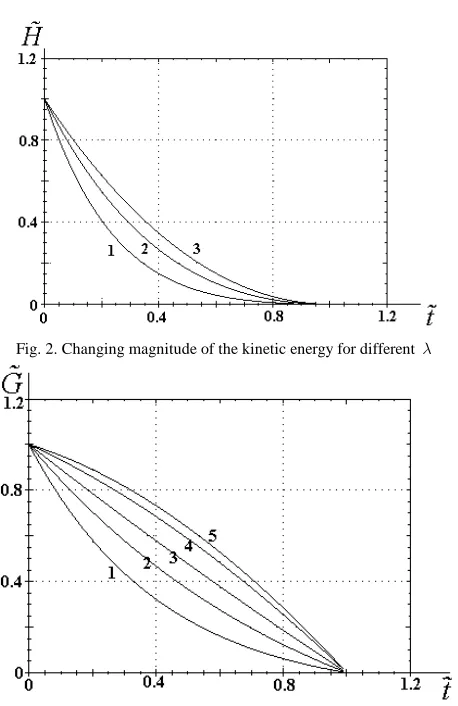
The change of P from 1 to 10-2 has no effect on the general behavior of the functions Gɶ=G tɶ ɶ( ) and Hɶ=H tɶ ɶ( ) because the torque of the viscous fluid in the cavity does not appear in the first equation of system (17) and its effect on the change of the kinetic energy is smaller than the influence
of the moment of resistance forces and the control moment. The numerical results show that, for the values of λ, b, and
P indicated above, the module of elliptic functions k2 insignificantly decreases from around 1 to 0.9996.
V. SOLUTION OF THE OPTIMAL DECELERATION PROBLEM UNDER THE ASSUMPTION b=b0 +βt
The deceleration time of a rigid body can be determined from Eq. (10); it depends on the coefficients β, b0, and λ characterizing the control moment and the moment of resistance forces, respectively. The numerical integration illustrates how the deceleration time depends on these parameters (see Fig. 5). Curves 1, 2, 3 illustrate the dependence of the deceleration time on the parameters β,
0
b , and λ, respectively. For each curve, the deceleration time was calculated in the range from 0.01 to 0.5 for the corresponding parameter (the values of the other parameters were taken to be 0.1). It can be seen that the deceleration time for all the curves is a minimized by the maximum values of the parameters in the admissible range. Curves 2 and 3 are close to straight lines, and curve 1 is close to an exponential curve. The minimum deceleration time of the rigid body was obtained for the parameter b0, which characterizes the value of the control moment at the initial time.
[image:5.595.49.273.56.236.2] [image:5.595.312.534.108.268.2]System of equations (17) was numerically integrated for Fig. 1. Changing magnitude of the kinetic moment for different λ
Fig. 2. Changing magnitude of the kinetic energy for different λ
Fig. 3. Changing magnitude of the kinetic moment for different b
Fig. 4. Changing magnitude of the kinetic energy for different b
[image:5.595.54.283.257.610.2]
Fig. 5. Dependence of the deceleration time on the parameters β,
0
b , and λ
[image:5.595.309.536.299.455.2]different values of parameters P, λ, b0, and β with account for the law b=b0 +βt. Figure 3 (curves 4 and 5) corresponds to the numerical calculation for constant parameters of resistance torque and viscous fluid torque in the cavity P=0.1 and λ=0.1 for different values of the control moment: b0 =0.1 and β =0.1 (curve 4), and
0 0.01
b = and β =0.1 (curve 5). Under this law of change in the control moment, the behavior of the function
( )
Gɶ=G tɶ ɶ is substantially different from that of the kinetic moment function at b=const.
We performed the numerical integration for constant parameters of the control moment under the law
0
b=b +βt at different values of the resistance torque. For 0.1
P = , β=0.1, and b0 =0.1, the numerical results are shown in Fig. 1, where λ=0.1 (curve 4) and λ=0.01 (curve 5). It is seen that the higher the coefficient of the resistance torque, the faster is the body deceleration. The decrease pattern of the kinetic moment differs from the function body shown in Fig. 3. The numerical analysis makes it possible to conclude that, for b=const, the body deceleration is faster in the first half of the dimensionless time tɶ, and, in the case
0
b=b +βt, it is faster in the second half.
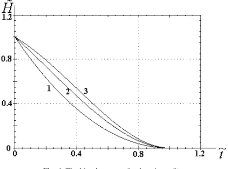
Figure 6 shows the results of numerical calculation of the rigid body kinetic energy for b=b0 +βt. We used the following values of the perturbing moment parameters:
0.1
P = and λ=0.1. The parameters of the control moment are: b0 =0.01 and β =0.01 (curve 1); b0 =0.1 and β =0.1 (curve 2); and b0 =0.01 and β =0.1 (curve 3). The behavior of the kinetic energy is similar to that
shown in Fig. 2. Here, the function Hɶ =H tɶ ɶ( ) at 0
b=b +βt decreases with lower gradients.
Investigation of the rigid body deceleration as k2 →1, which corresponds to trajectories of the kinetic moment vector near the separatrix was studied. The body motion for small values of k2 ≪1, which corresponds to the motions
that are close to rotations about the axis Oz1 was also studied.
VI. CONCLUSION
The problem of time-optimal deceleration of rotations of a dynamically nonsymmetric quasirigid body in a resistive medium was studied analytically and numerically. The asymptotic approach made is possible to determine the control, time (Bellman’s function), evolutions of the square of the magnitude of the elliptic functions modulus k2, and dimensionless kinetic energy and kinetic moment. The qualitative properties of the optimal motion were found.
REFERENCES
[1] F. L. Chernous’ko, “Motion of a Rigid Body with Cavities Filled with Viscous Fluid at Small Reynolds Numbers,” USSR Comput. Math. Math. Phys. 5, 99–127 (1965).
[2] L. D. Akulenko, D. D. Leshchenko, and A. L. Rachinskaya, “Evolution of Rotations of a Satellite with a Cavity Filled with Viscous Fluid,” in Mechanics of Solids, Issue 37 (OOO “Nord Komp’yuter”, Donetsk, 2007) [in Russian].
[3] L. D. Akulenko, D. D. Leshchenko, and F. L. Chernous’ko, “Fast Rotation of a Heavy Solid Body in a Dragging Medium about a Fixed Point,” Izv. Akad. Nauk SSSR, Mekhanika Tverdogo Tela, No. 3 (1982).
[4] V. N. Koshlyakov, Problems in Dynamics of Solid Bodies and in Applied Gyroscope Theory: Analitical Metods (Nauka, Moscow, 1985) [in Russian].
[5] E. J. Routh, Dynamics of a System of Rigid Bodies (Dover, Mineola, N.Y., 2005; Nauka, Moscow, 1983), Vol. 2.
[6] L. D. Akulenko, D. D. Leshchenko, and A. L. Rachinskaya, “Evolution of the Satellite Fast Rotation due to the Gravitational Torque in a Dragging Medium,” Mech. Solids 43, 173–184 (2008). [7] L. D. Akulenko, Problems and Methods of Optimal Control (Kluwer,
Dordrecht-Boston-London, 1994).
[8] L. D. Akulenko and D. D. Leshchenko, “Optimal Deceleration of Rotation of a Solid Body with Internal Degrees of Freedom,” Izv. RAN. TiSU, No. 2 (1995).
[9] D. D. Leshchenko, “Optimal Damping of Rotations of a Solid Body with Interior Degrees of Freedom with Respect to Speed,” J. Comput. Syst. Sci. Int. 5, 74–79 (1996).
[10] L. D. Akulenko, D. D. Leshchenko, and A. L. Rachinskaya, “Optimal Deceleration of Rotation of a Dynamically Symmetric Body with a Cavity Filled with Viscous Liquid in a Resistive Medium,” J. Comput. Syst. Sci.Int. 49, 222–226 (2010).
[11] L. D. Akulenko, Ya. S. Zinkevich, and D. D. Leshchenko, “Optimal Rotation Deceleration of a Dynamically Asymmetric Body in a Resistant Medium,” J. Comput. Syst. Sci. Int., 50, 14–19 (2011). [12] V. V. Beletskii, Motion of a Satellite about Its Center of Mass
(Nauka, Moscow, 1965) [in Russiian].
[image:6.595.40.272.211.383.2][13] I. S. Gradshtein, and I. M. Ryzhik, Tables of Integrals, Series, and Products (Nauka, Moscow, 1971; Academic, New York, 1965; San Diego:Academic, 1980).
Fig. 6. The kinetic energy for
0