Orcad
®
Layout
Copyright © 1985-2000 Cadence Design Systems, Inc. All rights reserved.
Trademarks
Allegro, Ambit, BuildGates, Cadence, Cadence logo, Concept, Diva, Dracula, Gate Ensemble, NC Verilog, OpenBook online documentation library, Orcad, Orcad Capture, PSpice, SourceLink online customer support, SPECCTRA, Spectre, Vampire, Verifault-XL, Verilog, Verilog-XL, and Virtuoso are registered trademarks of Cadence Design Systems, Inc.
Affirma, Assura, Cierto, Envisia, Mercury Plus, Quickturn, Radium, Silicon Ensemble, and SPECCTRAQuest are trademarks of Cadence Design Systems, Inc.
Alanza is a service mark of Cadence Design Systems, Inc.
All other brand and product names mentioned herein are used for identification purposes only and are registered trademarks, trademarks, or service marks of their respective holders.
Part Number 60-30-661 Second edition 31 May 2000
Cadence PCB Systems Division (PSD) offices
PSD main office (Portland) (503) 671-9500
PSD Irvine office (949) 788-6080
PSD Japan office 81-45-682-5770
PSD UK office 44-1256-381-400
PSD customer support (877) 237-4911
PSD web site www.orcad.com
PSD customer support web page www.orcad.com/technical/technical.asp
Contents
Before you begin vii
Welcome to OrCAD . . . vii
How to use this guide . . . viii
Symbols and conventions . . . viii
Related documentation . . . ix
About SmartRoute 11
Chapter 1
Neural networks . . . 12Neural costs . . . 14
Neural shapes . . . 15
Routing algorithms (passes) . . . 15
Angled direction by layer . . . 16
Routing time, power, and quality . . . 18
Routing time . . . 18
Routing power . . . 18
Routing quality . . . 19
Predicting routing time and percent of completion . . . 20
Getting started 21
Chapter 2
Calibrating SmartRoute . . . 22Starting SmartRoute . . . 22
The SmartRoute session frame . . . 23
Compatibility with Layout Plus . . . 24
Contents
The SmartRoute work environment 27
Chapter 3
SmartRoute menus . . . 28
New user hints . . . 30
The status bar . . . 30
Viewing the board . . . 32
Zoom functions . . . 32
Displaying the board density . . . 34
Getting information . . . 35
Opening and saving designs 37
Chapter 4
Opening a design . . . 38Saving a design . . . 38
Using backup . . . 39
Closing a design and exiting SmartRoute . . . 40
Setting up the board for routing 41
Chapter 5
Setting net properties . . . 42Setting parameters . . . 46
Layers . . . 47
Design parameters . . . 49
Analyzing routing parameters . . . 51
Specifying routing passes . . . 52
Contention . . . 56
Manufacturing passes . . . 57
Autorouting and batch routing 59
Chapter 6
Autorouting . . . 60Pre-route synopsis . . . 61
Running the autorouter . . . 61
Batch routing . . . 64
Setting up and routing two-layer boards . . . 66
Setting up and routing multilayer boards . . . 68
Contents
v
Editing the board 73
Chapter 7
Interactive routing . . . 74
AutoRoute Area . . . 74
AutoRoute Component . . . 75
AutoRoute Net . . . 75
AutoRoute One . . . 76
SketchATrack routing . . . 76
Manual routing . . . 78
Deleting routes . . . 80
Design checklist and common errors 81
Appendix A
Solving routing problems 85
Appendix B
The autorouter has stopped, the time counter has stopped, or the autor-outer is not advancing . . . 85The autorouter is too slow . . . 86
Router achieves low percentage (i.e., 75-85%) completion . . . 86
Upon returning to Layout Plus, a design rule check of the routed board finds errors . . . 87
SmartRoute displays the following message: LOW RESOURCES . . . 87
The router seems slow when routing angled layers . . . 88
Only a few connections or contentions are left unrouted . . . 88
Component placement strategies . . . 91
Routing channel . . . 91
Do not block routing channels . . . 92
SMD spacing . . . 92
SMD location on top and bottom layers . . . 93
More tips and tricks . . . 94
Suggested reference material 97
Appendix C
Before you begin
Welcome to OrCAD
OrCAD offers a total solution for your core design tasks: schematic- and VHDL-based design entry; FPGA and CPLD design synthesis; digital, analog, and mixed-signal simulation; and printed circuit board layout. What’s more, OrCAD’s products are a suite of applications built around an engineer's design flow—not just a collection of
Before you begin
How to use this guide
This guide is designed so you can quickly find the information you need to use SmartRoute.
Symbols and conventions
OrCAD printed documentation uses a few special symbols and conventions.
Notation Examples Description
C+r Press C+r Means to hold down the C key while
pressing r. A, f, o From the File menu, choose Open (A, f,
o)
Means that you have two options. You can use the mouse to choose the Open command from the File menu, or you can press each of the keys in
parentheses in order: first A, then f, then o.
Monospace font In the Part Name text box, type PARAM. Text that you type is shown in monospace font. In the example, you type the characters P, A, R, A, and
M.
UPPERCASE In Capture, open CLIPPERA.DSN. Path and filenames are shown in uppercase. In the example, you open the design file named CLIPPERA.DSN. Italics In Capture, save design_name.DSN. Information that you are to provide is
How to use this guide
ix
Related documentation
In addition to this guide, you can find technical product information in the online Help, online books, OrCAD’s technical web site, as well as other books. The table below describes the types of technical documentation provided with SmartRoute.
This documentation component . . . Provides this . . .
This guide—
SmartRoute User’s Guide
A comprehensive guide for understanding and using the features available in SmartRoute.
Online Help Comprehensive information for understanding and using the features available in SmartRoute.
You can access Help from the Help menu in
SmartRoute, by choosing the Help button in a dialog box, or by pressing 1. Topics include:
• Explanations and instructions for common tasks. • Descriptions of menu commands, dialog boxes, tools on
the toolbar and tool palettes, and the status bar. • Error messages and glossary terms.
• Reference information. • Product support information.
You can get context-sensitive help for a error message by placing your cursor in the error message line in the session log and pressing 1.
Before you begin
ODN—OrCAD Design Network at www.orcad.com/odn
An internet-based technical support solution. ODN provides a variety of options for receiving and accessing design and technical information. ODN provides:
• A Knowledge Base with thousands of answers to questions on topics ranging from schematic design entry and VHDL-based programmable logic design to printed circuit board layout methodologies.
• A Knowledge Exchange forum for you to exchange information, ideas, and dialog with OrCAD users and technical experts from around the world. A list of new postings appears each time you visit the Knowledge Exchange, for a quick update of what’s new since your last visit.
• Tech Tips that deliver up-to-the-minute product information in your email box. Stay informed about the latest advances, tips, and announcements on your OrCAD product.
• Online technical support via the Tech Support
Connection. Use this service to submit technical support incidents online. Create submissions, upload files, track your incidents and add comments directly into OrCAD’s support database.
About SmartRoute
1
Autorouters have two primary objectives: to route boards to 100% completion and to route boards quickly.
SmartRoute adds a third objective—quality of routing. Historically, professional board designers have
complained that autorouted boards do not provide the same quality as manually routed boards. The side effects of autorouting can include too many vias, tracks that wander, vertical layers with too many horizontal segments and vice versa, unevenly spaced tracks, and more.
Chapter 1 About SmartRoute
Neural networks
A neural network is a subset of artificial intelligence. SmartRoute uses a neural network for routing
intelligence, and time and completion projection. It is among the first CAD software products to employ artificial intelligence.
A neural network analyzes problems for which there is no explicit solution. Instead, there may be a variety of solutions, some better than others. Consider an analogy. There are a variety of ways a board can be routed, some of which are better than others. The designer selects the best solution, considering all the options and possible
outcomes. This is also the function of the neural network and the other neural utilities in SmartRoute: to provide intelligence that will result in the “best” routing.
While the concept of a neural network is relatively new to EDA, it is widely used elsewhere. One of the better known uses is in the financial marketplace, where it is used in analyzing and predicting stock market trends. Virtually every financial institution involved in stock and currency trading uses neural networks as an investment tool. Other areas where neural networks are used extensively are in character recognition and speech recognition.
In order for a neural network to produce a solution, it must have input data consisting of multiple sets of data similar to data describing the solution. The neural network studies this historical data, a feature called “neural network training.”
Neural networks
13 For example, to predict the closing stock price of an
electronic company tomorrow, you need 200-300 days of previous, historical closing data on the stock, as well as 200-300 previous closing days of other variables that you think might have a bearing on predicting the stock’s closing value. These variables might be the Index of Electronics stocks, NYSE closing prices on leading computer manufacturers’ stocks, and so on.
Additionally, you might want to include economic factors, such as the prime rate, the Eurodollar, Dmark, Yen, and so on. Finally, and surprisingly, you might want to include some seemingly unrelated variables, such as new housing starts.
The neural network analysis attempts to identify relationships among the various variables and the item whose price is being predicted. A direct relationship such as the price of crude oil and an oil company is obvious. An indirect relationship is not as obvious—for example, the change in the closing price of a fast food chain and the lower than average seasonal rainfall in the coffee-growing regions of South America. The point is that in a relatively short period of time, a neural network can find direct and indirect associations.
Chapter 1 About SmartRoute
The boards selected had all the characteristics associated with quality routing, such as diagonal routing, primary direction by layer, minimum via count, minimized wandering, and bus structure. These characteristics were used to establish neural costs. The SmartRoute neural network determined the relationships between the physical characteristics of these boards and the board being autorouted.
Appendix C, Suggested reference material includes a listing of suggested reading material for further information on neural networks.
Neural costs
All autorouters use a feature called cost for their routing algorithms. Cost determines how difficult it is for the autorouter to perform a given activity. Using vias as an example, on a scale of 1-100, a via cost of 1 makes it easy to install vias, and in the absence of other costs, results in a board with many vias. A via cost of 100, on the other hand, prevents the placement of vias, even in areas of the board where vias are desirable.
Neural costs are not static; instead, they change
dynamically throughout the routing process. The neural costs are adapted in terms of routing completion. They are adjusted as the board’s density changes due to routing. The dynamic adaptation of cost applies for all cost-driven parameters.
Neural shapes
15
Neural shapes
Shape-based routing has replaced gridded routing in today’s autorouters. Conventional shapes provide immense advantages in routing speed and in routing flexibility; however, conventional shapes and
shape-based routing do not address routing quality.
The SmartRoute neural shape concept successfully addresses the issue of routing quality. Specifically, the SmartRoute neural shapes consist of polygons of all different sizes and shapes. This, together with routing algorithms that permit X and Y routing, 45° routing, and that are capable of selecting a routing direction by layer from multiple choices (horizontal, vertical, 45° up, 45° down, 1 o’clock, 2 o’clock, 4 o’clock and 5 o’clock), provide the flexibility to enhance routing quality.
Chapter 1 About SmartRoute
Angled direction by layer
In SmartRoute, you can direct the autorouter to route in non-orthogonal directions on each layer of a multilayer board.
The autorouter assigns a connection to a layer based on the user-assigned layer direction and the connection’s slope or tangent. SmartRoute then routes the track along the slant or approximate hypotenuse of a triangle, as opposed to routing orthogonally along the X and Y legs of the hypotenuse. When routing using a direction by layer:
n The approximate hypotenuse track length is shorter
than the X and Y length.
n The board will have fewer vias.
Shorter track length provides more flexibility when placing parts. Combined with fewer numbers of vias per connection, these considerations greatly accelerate the routing process. Additionally, there is an increased probability of routing to 100% completion.
Angled direction by layer
17 The figure below shows two layers of a six-layer board
with layers routed at 45° up and 45° down.
The basic movement uses long 45° diagonal segments with incremental orthogonal steps that align the track’s direction with the selected layer direction.
Chapter 1 About SmartRoute
Routing time, power, and quality
This section discusses routing time, power, and quality in autorouting.Routing time
Routing time, historically, has been one of the prime criteria for evaluating autorouters. But, the rapid evolution of both software and high-performance hardware has de-emphasized the importance of routing time. For example, when teamed with powerful PCs, a good autorouter should route nearly all six- to eight-layer boards with 4,000-5,000 connections in about 5 to 15 hours.
Routing power
Routing power, or the ability to route close to 100% of the connections, has always been extremely important in autorouting. And, it is even more important today.
Designers know that if an autorouter routes only 95% to 96% of the connections, the time required to interactively complete the 4% to 5% of unrouted connections is as great as the time it took to autoroute the first 95%. If an
autorouter achieves only 90% to 93%, many designers will start over, routing interactively from scratch.
Routing time, power, and quality
19 Is it better to have an unrouted connection, or a routed
track with a contention? Experienced designers prefer the track be routed with the contention rather than being left unrouted. This is because the contention is normally confined only to one area along the track, and it is easier to resolve a problem in one area than to make room for an entirely unrouted connection.
Routing quality
Routing quality is somewhat different from routing time and routing power in that it is evaluated in both subjective and objective terms; that is, you may consider measurable criteria as well as aesthetic criteria when evaluating the quality of a routed board. The measurable criteria include total number of vias, total amount of copper (tracks), average track length, wandering or long tracks, violation of direction by layer settings, absence of acute angles, and equal spacing of tracks between pads.
Although difficult to measure, you will recognize quality routing when you see it. The elements that define quality routing are as follows:
n A preference for 45° diagonal routing over X and Y
orthogonal segments
n The ability to assign directions (other than X or Y) to
different layers
n The collection of connections that bridge two areas or
parts on the board into a “bundle” of tracks, all using a similar track pattern
n A minimization of vias
n A minimization of wandering tracks
Chapter 1 About SmartRoute
Predicting routing time and
percent of completion
In SmartRoute, you can use the Analyze Parameters tool to predict routing time and routing completion. The prediction is an estimate, which can be fairly close or wildly inaccurate, depending on the complexity of the design. The more “average” the board is, the more accurate the prediction. The prediction is most useful as a measure of the effect of changing placements, spacing rules, and so on.
SmartRoute’s neural network is familiar with the
standard boards used today: two-, four-, six-, eight-, ten-, and sixteen-layer boards, through-hole, SMD top, SMD bottom, fine-pitch SMD, and PGA. Additionally, the parameters (pad size, spacing, via size, and so on) are based on the practices of skilled designers.
The neural network will not recognize boards in excess of 16 layers, 20" x 20", or with unconventional design parameters, such as a 75 mils via or IC pad. You can route these boards using SmartRoute, but the Analyze
Parameters tool will not yield accurate results.
Getting started
2
Chapter 2 Getting started
Calibrating SmartRoute
After installation, but before using SmartRoute, OrCAD recommends that you run the calibration program. Calibration loads a board into SmartRoute and routes it. From the length of time it takes to route this board on your system, SmartRoute can assess your system’s impact on routing speed. Calibration significantly affects the accuracy of the Analyze Parameters tool, which you can use to predict the routing time and percentage of
completion for a board.
To calibrate SmartRoute
1 From the Windows Start menu, choose Programs.
2 Choose the OrCAD Design Desktop program group
and then choose SmartRoute Calibrate. SmartRoute opens and loads the calibration board, and routes it.
Starting SmartRoute
Start SmartRoute from the Layout Plus session frame. Note
Starting SmartRoute by double-clicking on SROUTE.EXE opens
SmartRoute in demonstration mode and you cannot save your
design.
To start SmartRoute
1 From the Tools menu in the Layout Plus session frame,
choose SmartRoute.
Note
If you are running a version of Layout other than Layout Plus, the
The SmartRoute session frame
23
The SmartRoute session frame
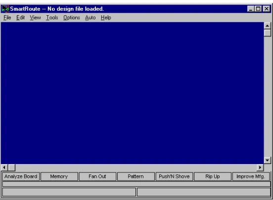
[image:23.612.101.377.212.415.2]Once you start SmartRoute, you see the SmartRoute session frame. This is the area where the board is displayed.
Figure 1 The SmartRoute session frame.
Before you load a design, the title bar at the top of the session frame reads, “No design file loaded.” When you open a design, that is replaced with the design’s name. In SmartRoute, you can only open one design file at a time.
At the bottom of the session frame, you see the names of the seven routing passes available for the autorouting sequence.
Chapter 2 Getting started
Compatibility with Layout Plus
The following Layout Plus features are not yet supported in SmartRoute:n Display (dot) grid
n AutoPan
n Square vias
n Arcs in connections
n High-contrast mode
Memory
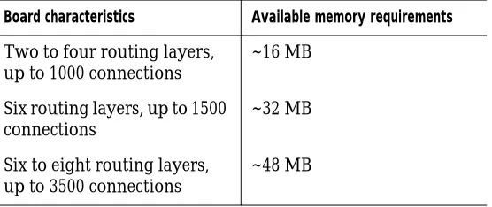
For general use, 32 MB of RAM is the recommended minimum amount of RAM. For routing larger boards (four layers, 2,000 connections), more memory is
recommended. For boards with six or more routing layers and over 2,500 connections, a minimum of 64 MB of RAM is recommended.
SmartRoute uses about 10% to 15% more memory than other shape-based autorouters. This additional memory is used to create the multi-sided neural shapes that in turn permit the diagonal and angled routing that contributes to SmartRoute’s high-quality routing.
Memory
25 On the line labeled Total Memory, examine the values for
Total, Used, and Available. If you have 32 MB on your PC, and if the value for Total is 32 MB, but the value for Free is significantly less (5 to 6 MB), you can retrieve and use some of this memory. To do so, determine where the additional memory is used and release it.
n If your CONFIG.SYS file has a “device” command for
“RAMDRIVE,” it may be using too much memory.
Temporarily, reduce this amount by typing REM at the
beginning of the line. Reboot Windows. When you are done using SmartRoute, you can restore your RAM drive to its original size.
n If your CONFIG.SYS or AUTOEXEC.BAT files load
“SmartDrive,” it may be using too much memory.
Temporarily reduce this amount by typing REM at the
beginning of the line. Reboot Windows.
The SmartRoute work
environment
3
Chapter 3 The SmartRoute work environment
SmartRoute menus
SmartRoute’s commands are located on pull-down and pop-up menus. SmartRoute menus are active even when autorouting is in progress and the hourglass is active, although some commands are dimmed and unavailable for selection during autorouting.
The pull-down menus include File, Edit, View, Tool, Options, Auto, and Help. Their functions are as follows:
File menu
The File menu includes commands for opening, closing, and saving designs, as well as backup and restoration commands.
Edit menu
The Edit menu includes the Undo and Redo commands, and a Find/Goto command.
View menu
The View menu includes commands for viewing board density, clearing and redrawing the screen, and various zooming commands.
Tools menu
The Tools menu includes commands for highlighting and identifying nets, identifying pins, sketching an
approximate track for SmartRoute to follow, and manually routing.
For information on opening, closing, and saving designs, see Chapter 4, Opening and saving designs.
SmartRoute menus
29
Options menu
The Options menu includes routing setup commands, such as Net Properties, Parameters, and Routing Passes. It also includes the Backup Interval command, with which you can set the duration between automatic backups. There is also a Batch Setup command for setting batch routing options, and the Hints Checkbox command for enabling or disabling the SmartRoute new user hints feature.
Auto menu
The Auto menu includes commands for running the pre-route synopsis and autorouting. It also includes commands for interactive and manual routing.
Help menu
The Help menu provides access to the SmartRoute online help. The SmartRoute online help provides a description of every command and dialog box in SmartRoute, and includes key processes and reference information. The Help menu also includes the About SmartRoute command, which displays the version number, licensing, and copyright information for SmartRoute.
Pop-up menus
The SmartRoute pop-up menus provide easy access to frequently used commands. You can display pop-up menus by pressing the right mouse button. The pop-up menus provide commands that are appropriate for the current activity. For example, during autorouting, the pop-up menu displays the commands Pause and Stop. However, if the autorouter has been paused, the pop-up menu displays the commands Restart and Stop.
Tip
During autorouting, SmartRoute displays an hourglass. Even when
this hourglass is displayed, you can still access menu commands
and pop-up menu commands, although some commands will be
dimmed and unavailable for selection.
For information on setting up the board for routing, see Chapter 5, Setting up the board for routing. For information on using the new user hints feature, see New user hints on page 30.
Chapter 3 The SmartRoute work environment
New user hints
A number of SmartRoute menu commands provide a SmartRoute feature called New User Hints. The hints consist of command and dialog box descriptions and tips. Use the hints as a learning tool to help you become familiar with SmartRoute. After you have become familiar with SmartRoute and no longer need the hints, you may disable them individually, or all at once. To disable one hint, select the Click to turn off hint message option in the hint window, then choose the OK button. To disable all hints, choose Hints Checkbox from the Options menu. In the dialog box that displays, select the Turn Hints OFF option, then choose the OK button.
The status bar
The status bar, located at the bottom of the session frame, displays information appropriate to the activity you are performing.
During autorouting, the status bar contains three levels of information. The top level contains the names of the seven passes of the autorouting sequence. As routing
The status bar
31 For many commands, the status bar provides help tips.
For example, when you choose the Zoom In command, the status bar displays the following message:
Press and hold at center of zoom area.
After you press and hold the mouse button, the message changes:
Drag cursor to enclose zoom area.
When you release the mouse button, the status bar displays yet another message:
Select center of another zoom area.
Chapter 3 The SmartRoute work environment
Viewing the board
In SmartRoute, you can easily view different areas of the board, get information about specific pins and nets, and find parts, pads, and locations on the board. You can also run a board density check using the Density Graph command.
Zoom functions
There are four commands in SmartRoute that you can use to change the view of the board displayed on the screen: Zoom In, Zoom Out, Zoom Center, and Zoom All (Fit).
n The Zoom In command magnifies a selected area of
the board.
n The Zoom Out command increases the board area
displayed.
n The Zoom Center command centers the selected area
in the display.
n The Zoom All (Fit) command displays the entire board
in the display.
To magnify an area of the board
1 From the View menu, choose Zoom In. The pointer
becomes a “Z.”
2 Position the pointer at the upper left corner of the area
Viewing the board
33 Note
There may be a delay when you choose the Zoom In command,
especially if you are autorouting a very dense board, and the
autorouter is currently routing a long connection. In this case, the
command will be performed when the current connection is
completed.
To view more of the board
1 From the View menu, choose Zoom Out. The pointer
changes to a “Z.”
2 Place the pointer at the center of the area you want to
view and click the left mouse button.
3 Press the E key to exit zoom mode.
To center an area of the board in the display
1 From the View menu, choose Zoom Center.
2 Position the pointer at the location you want to center
in the display and click the left mouse button. The selected area moves to the center of the display. The scale remains unchanged.
3 Press the E key to exit zoom mode.
To view the whole board in the display
1 From the View menu, choose Zoom All (Fit). The
entire board is displayed on the screen.
2 Press the E key to exit zoom mode.
Chapter 3 The SmartRoute work environment
Displaying the board density
The Density Graph command displays an extremely accurate, color-coded, graphical density map of the board, with red representing the hottest or most dense areas, and blue representing the least dense.
The density graph considers unrouted connections, routed segments, and pads to calculate density. It provides you with a detailed analysis of routing density due to component placement.
When you are working with SmartRoute, you should use SmartRoute’s density graph, rather than Layout Plus’s, because Layout Plus’s density graph is not optimized to provide the information valuable to SmartRoute.
To display board density
1 From the View menu, choose Density Graph. The
color-coded density map displays.
Use the following as a guide for evaluating the density map:
Best The best board layouts display no red high-density
areas. This is highly desirable, but with high-density boards, not always possible.
Worst It is difficult—perhaps impossible—to route a board with one or more very large bright red areas, commonly referred to as “connection hot spots.” A large hot spot could encompass 10% to 20% of the total board area. These are problem areas; reposition components to reduce the density in these areas.
Viewing the board
35
To exit the density map
1 From the View menu, choose Redraw Screen.
Getting information
Use the Find/Goto command on the Edit menu, and the Highlight Net, Identify Net, and Identify Pin commands on the Tools menu to locate or obtain information on the nets and pins in the design.
To find a component, pad, or location on the board
1 From the Edit menu, choose Find/Goto. The Find
dialog box displays.
2 Perform one of the following tasks:
n To find a part, enter the reference designator (for
example, U9).
n To find a pad, enter the reference designator and
pad number (for example, U9.1).
n To find a location, enter its X and Y coordinates
(for example, 4982, 5015).
Chapter 3 The SmartRoute work environment
To highlight a net
1 From the Tools menu, choose Highlight Net. The
Highlight Net dialog box displays.
2 Select the net that you want to highlight.
3 Choose the Highlight button. All connections of the
selected net are displayed in the highlight color. Note
Highlighting a net is not persistent after a pan or zoom, and
changing a highlight value for any net in SmartRoute causes any
previous highlights to be turned off for all other nets.
To turn off a net’s highlight
1 From the Tools menu, choose Highlight Net. The
Highlight Net dialog box displays.
2 Select the net for which you want to turn off the
highlight.
3 Choose the End Highlight button.
To identify a net or pin
1 From the Tools menu, choose Identify Net or Identify
Pin. The pointer changes to a vertical arrow.
2 Select the desired net or pin. For a net, the connection
Opening and saving designs
4
Chapter 4 Opening and saving designs
Opening a design
You open Layout Plus .MAX files in SmartRoute using the Open command.
To open a design
1 From the File menu, choose Open. The Open Design
File dialog box displays.
2 Locate and select a .MAX design file.
3 Choose the OK button.
Tip
The files that you have opened most recently are listed at the
bottom of the File menu. You can select files from this list to open
them. This is the fastest way to open designs that you have worked
on recently.
Saving a design
You save SmartRoute designs using the Save As command. You can also use the Backup command to automatically save designs.
To save a design
1 From the File menu, choose Save As. The Save As
dialog box displays.
2 To save a board under a new name, enter the name of
the file, locate the target directory, and choose the OK button.
Saving a design
39 Note
There is no Save command in SmartRoute, only a Save As
command. However, you can use the Backup command to save a
file without specifying a file name. See Using backup in this chapter
for more information.
Using backup
Three backup commands make up the SmartRoute backup feature: Backup, Restore Backup, and Backup Interval. The Backup command automatically saves the design and generates a file called SRBACK.RBK at the intervals you establish. Subsequent backups overwrite the previous SRBACK.RBK. The advantage of backup is that, in the event of power outages, hardware failure, or for whatever reason, you can go back to an earlier sequence in the autorouting process. To open the last saved version of the design, use the Restore Backup command.
To set the backup interval
1 From the Options menu, choose Backup Interval. The
Auto Backup Interval dialog box displays.
2 In the Make new backup every n minutes text box,
enter the interval at which you want SmartRoute to save the design and create the backup file,
SRBACK.RBK. If you enter 0 (zero) in this text box, you disable the backup feature.
3 Choose the OK button.
Tip
OrCAD recommends setting backup intervals of 10 minutes.
Note
Backup intervals reflect “real time.”
To make a backup
1 From the File menu, choose Backup. SmartRoute saves
Chapter 4 Opening and saving designs
To open the last saved SRBACK.RBK file
1 From the File menu, choose Restore Backup.
SmartRoute opens the current backup file, SRBACK.RBK.
Tip
If you restore a board, you should immediately choose the Save As
command and save the file with the correct filename.
Closing a design and exiting
SmartRoute
To close a design in SmartRoute, you must either open another design, or exit SmartRoute (there is no Close command). For information on opening a design, see Opening a design in this chapter.
To exit SmartRoute
1 From the File menu, choose Exit. If there are unsaved
changes in the design, SmartRoute prompts you with the following three options. Select the desired option.
Save and Exit SmartRoute opens the Save As dialog box. Choose the OK button. SmartRoute saves the design and exits.
Discard and Exit SmartRoute discards the unsaved changes and exits.
Setting up the board for
routing
5
Setting up the board is the most important part of the routing process. There are three items to consider when setting up the board for routing in SmartRoute: net properties, parameters, and routing passes. When routing a board using SmartRoute, the vast majority of setup activities are performed in Layout Plus. When you load the board into SmartRoute, you are mainly concerned with checking the values displayed to confirm that they reflect what you want.
This chapter describes each of the following in detail.
Net properties Confirm, and change if desired, the net properties that you set in Layout Plus, such as routing weight and track width.
Parameters Confirm, and change if desired, various parameters used by the autorouter, such as number of layers, direction of tracks on layers, pad sizes, and more.
Routing passes Select the routing passes that you want the autorouter to perform during the autorouting process. OrCAD recommends that you use the default passes set by SmartRoute.
Chapter 5 Setting up the board for routing
Setting net properties
The first step in setting up the board for routing is to check the net properties that SmartRoute received from Layout Plus. You can do this in the Net Properties dialog box. The dialog box is organized like a spreadsheet. The names of all the nets in the design are listed on the left side. A net name can be brought into view using either the vertical scroll bar or by entering the net name in the Find Net text box at the bottom of the dialog box. As you spell the name of the net, it is moved to the top of the spreadsheet.
To change net properties in SmartRoute
1 From the Options menu, choose Net Properties. The
Net Properties dialog box displays.
2 Enter the name of the net that you want to view in the
Find Net text box.
3 Modify the value for Routing Weight, Length
Minimize, Route Action, or Track Width by selecting a new value from the appropriate drop-down list. For a detailed description of each option, read the dialog box option descriptions below.
4 Choose the OK button.
Setting net properties
43
Example
In this example, you modify the net properties for a four-layer board, in which two layers (top and bottom) are used for routing signal connections, and two planes are reserved for the power and ground nets. When signal connections are to be routed, and power and ground are to be reserved for planes, set the power (VCC) and ground (GND) nets as planes using the Route Action option in the Net Properties dialog box.
1 In the Find Net text box, type GND to find the ground
net.
2 In the Route Action column, note the available
options. For this example, you want the GND net to be fanned out (as for a plane); therefore, select the Fanout/Plane option.
3 Repeat steps 1 and 2 for the VCC net.
4 Choose the OK button.
The Net Properties dialog box
Chapter 5 Setting up the board for routing
Routing Weight allows you to select the order of routing. SmartRoute first selects all nets with a weight of 81-100 that have unrouted segments, then attempts to route them starting with the highest weight and the widest width. It then selects all nets with a weight of 61-100 (including routed nets), and attempts to route them starting with the highest weight and the widest width. During this pass, it also attempts to remove conflicts from the routed nets. Then, SmartRoute continues in the same manner with nets with a weight of 0-60. If you don’t select a Routing Weight, the priority of routing is determined by the neural network.
The Routing Weight values in SmartRoute reflect the values for weight set in Layout Plus. You can change these values in SmartRoute. Keep in mind that slight increments in the routing priority value have the same effect as dramatic increments. For example, if all nets are given a routing priority of 50, and you change the routing priority of one net to 51, the net set at 51 will be routed first. There is no need to set that net’s routing priority to 90.
Length Minimize SmartRoute minimizes the lengths of the unrouted connections on the board immediately before autorouting, in accordance with the Length Minimize setting for each net. The setting options are described below.
None. No minimization occurs.
Min Dist (minimum distance). The connections are rearranged to result in a minimum total length.
Daisy. The net retains the “from-to” sequence in the board design.
Setting net properties
45 Route Action The route action property provides the
router with instructions for routing a net.
Default. If a net is connected to SMD pads, and if there are no more than two routing layers on the board, the net is routed without being fanned out from the SMD pad; on a board with more than two routing layers, the net is fanned out, then routed. Default is the normal mode for the autorouter and should not be changed unless for a specific purpose.
Route. The system routes the net without a fanout. No Route. The net is ignored by the autorouter.
Locked. When Locked is selected, the routed connections in the net cannot be rerouted, pushed, or shoved. Partially routed connections may sometimes still be shoved. Fanout/Route. The net is fanned out from an SMD or edge finger pad, then routed.
Fanout/Plane. The net is fanned out from the edge finger or SMD pad but left in an unrouted state (used for
connecting to power and ground planes).
Track Width The default entry is the primary track width as set in Layout Plus. OrCAD recommends that you do not change this value, but if you wish to change it, select a new width from the drop-down list.
If the width of a net is too thick to exit a pad, SmartRoute will use the net width from a standard set of net widths in SROUTE.INI that is less than or equal to the width of the pad. SmartRoute will not drop the width of the net lower than the minimum width for the net specified in Layout Plus.
Chapter 5 Setting up the board for routing
Setting parameters
After the net properties have been set, set the design parameters. There are three categories of parameters. They are all controlled in the Parameters dialog box.
n Layers
n Design parameters
n Analyze parameters
To change the parameters for routing
1 From the Options menu, choose Parameters. The
Parameters dialog box displays.
2 To bias the direction for routing on each layer, select
the desired option from the drop-down list adjacent to the layer name.
3 Change the parameters for Units, Via Type, or
Channel by selecting the appropriate options from the drop-down lists.
4 Change the parameters for Primary Pad, Via Width,
Primary Track, or Clearance by typing new values in the text boxes.
5 Choose the Analyze Parameters button. SmartRoute
analyzes the effects of the parameters that you set, and displays the results at the bottom of the dialog box.
6 When your parameter settings are as desired, choose
the OK button.
For information on the layer options in the Parameters dialog box, see Layers on page 47.
Note OrCAD recommends that you set the parameter values in Layout Plus, and then start SmartRoute. For more information on parameters, see Design parameters on page 49.
Setting parameters
47
The Parameters dialog box
Layers
The Layers group box lists the copper layers as defined in Layout Plus. You can select a direction in which routing will be biased for each layer. The choices are listed below.
Best Choice SmartRoute selects the direction for the layer.
Disabled No routing occurs on the layer.
Fanout The router will fanout vias on this layer but will not otherwise route on it. Use this option when you wish to fanout the layer containing the SMD pads and also restrict routing on that layer.
Plane The layer is reserved for use as a plane layer upon its return to Layout Plus. When this option is selected, the layer is no longer displayed in the Parameters dialog box.
Vertical The tracks are biased to be routed vertically.
Chapter 5 Setting up the board for routing
Any Direction The router is not biased in any direction. The suggested use for this option is on the third layer of a three-layer board. Do not use this option on more than one layer.
Angled options Options include right and left 45° angles, 1 o’clock, 2 o’clock, 4 o’clock, and 5 o’clock angles. These options will bias the layer in the direction selected. The options may be used for all layers on a multilayer board, although top and bottom layers are usually horizontally or vertically biased. These options are usually used by board designers to achieve shorter track lengths and fewer vias. These options can only be used on multilayer boards.
Example
In this example, you are routing the top and bottom layers and reserving layers 2 and 3 for planes. This means that during routing, tracks are not placed on layers 2 and 3. Also, the design, loaded as a four-layer board from Layout Plus, is returned to Layout Plus with layers 2 and 3 reserved for plane activity.
1 From the Options menu, choose Parameters. The
Parameters dialog box displays.
2 For layer 2, select Plane. Layer 2 is reserved for use as
a plane layer.
3 For layer 3, select Plane. Layer 3 is reserved for use as
a plane layer.
4 For the top layer, select Horizontal from the
drop-down list. The top layer of the board will be routed with a horizontal bias.
5 For the bottom layer, select Vertical from the
drop-down list. The bottom layer of the board will be Summary—While it is a good practice to
Setting parameters
49
Design parameters
Parameters are read directly from Layout Plus. In the Parameters dialog box, you can check the parameters you set in Layout Plus—including units, pad and via width, track width, and clearance—to make sure they display as you expect.
Before the new parameter settings are accepted in SmartRoute, you must choose the OK button in the Parameters dialog box and respond to the questions that display. The answers you provide confirm your decision to modify parameters before the changes are accepted by SmartRoute.
Note
Always check the Primary Pad, Via Width, Primary Track, and
Clearance parameters to make sure that the values displayed are
what you would expect from Layout Plus.
The design parameter options are described below.
Units From the drop-down list, select the desired data structure units for autorouting. OrCAD recommends that you use the same unit structure that you used in Layout Plus.
Via Type From the drop-down list, select the type of vias that you want to use on your board.
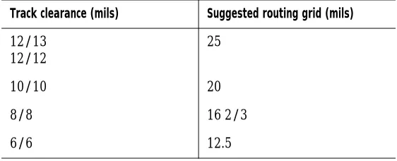
Channel In SmartRoute, the channel size that displays is automatically calculated by SmartRoute for your board. To calculate this value, SmartRoute adds the most frequently used track width on the board and the most common track-to-track clearance on the board.
Chapter 5 Setting up the board for routing
Note
Channel size may not be exactly the same as the system grid
specified in Layout Plus; channel size is calculated independently by
SmartRoute using the primary track width and clearance
parameter values in Layout Plus. For example, if you are routing a
board with 12 mils tracks and 13 mils clearance, SmartRoute sets
the routing channel to 25 mils.
OrCAD strongly recommends that you use the default channel size calculated by SmartRoute. When you return to Layout Plus, the system grid value will reflect the channel size selected by SmartRoute. If you have different grid requirements, you must change the system grid in Layout Plus.
Note
Note that if you change the Primary Track value or spacing rules,
channel size is recalculated after you choose the OK button in the
Parameters dialog box.
SmartRoute is a gridless router. It will try to place tracks on the
channel specified, but on dense boards this may not be possible.
Therefore, changing the channel value for a dense board may have
little effect on routing in SmartRoute.
Primary Pad The Primary Pad option displays the diameter width of the most commonly used pad on the board. If there are no through-hole pads, the Primary Pad option displays the width of the largest SMD pad.
For instance, on a board with 1000 pads from 50
components of various sizes, there could be 20 different pad sizes and shapes. The most common pad shape and size is displayed for the Primary Pad option.
Via Width The via width is the same as the first via defined in Layout Plus. SmartRoute, however, will choose the best via size for a given situation when routing.
Setting parameters
51 Clearance The Clearance option specifies the spacing
required between tracks (track-to-track clearance). This value is defined in Layout Plus.
Analyzing routing parameters
The Analyze Parameters feature is unique to SmartRoute. With this feature, you can estimate the routing time and percentage of route completion for the active board using the current parameters.
Furthermore, you can conduct “what if” exercises with the parameter settings, trying a number of different
configurations. The Analyze Parameters option estimates the settings’ effect on routing time and routing success.
The more “average” the board is, the more accurate the prediction of routing time and completion for the board. The prediction may be off by varying degrees. It is most useful as a measure of the effect of changing placements, spacing rules, and so on.
To analyze the selected parameters effect on routing
1 From the Options menu, choose Parameters. The
Parameters dialog box displays.
2 Choose the Analyze Parameters button. The estimated
time and completion for the board display at the bottom of the dialog box.
Chapter 5 Setting up the board for routing
Specifying routing passes
In the Routing Passes dialog box, you can enable various routing passes that will be used during the autorouting sequence, as well as set options for manufacturing.
OrCAD strongly recommends that you run all the passes using the default routing pass setup without modification. However, there are some instances in which only one or more of the routing passes should be activated.
n You have a very dense SMD board and you are not
sure that all of the pads will be fanned out (with the current placement). In this situation, select only Fan Out Used SMD Pins and deselect the other routing passes. When you autoroute the board, only the Fan Out Used SMD Pins routing pass is performed. Fanout failures are marked with a small yellow circle with an X in the center. If there are many failures, you should change the placement on the board.
n You have a true memory bank on your board and you
are concerned with where it should be placed and how the components should be oriented. In this situation, select only the Memory routing pass to evaluate the memory pattern.
Before the routing passes are run, SmartRoute analyzes the board. During this phase, the board is scanned and the appropriate neural costs are applied by the neural network. Once this is finished, the specified routing passes are performed.
To specify routing passes
1 From the Options menu, choose Routing Passes. The
Specifying routing passes
53 Note
During autorouting, the status bar contains three levels of
information about the routing passes. The top level contains the
names of the seven passes of the autorouting sequence. As routing
progresses, the pass that SmartRoute is currently executing is red.
The next level is a red line that represents the progress of the
current routing pass. The third level is the text that displays
beneath the red line. This text provides information about the
status of the autorouting sequence.
Example
In this example, you are routing a very dense four-layer SMD board. You need to run Fan Out Used SMD Pins first. If you have less than 10% fanout failure, you can
autoroute the board.
1 From the Options menu, choose Routing Passes. The
Routing Passes dialog box displays.
2 Select the Fan Out Used SMD Pins option and deselect
all other routing passes in the dialog box, then choose the OK button.
3 From the Auto menu, choose AutoRoute Board.
SmartRoute performs fanout.
4 Check the board to see that you have less than 10%
fanout failure. A failure is indicated by a small yellow circle with an X in the center.
n If so, open the Routing Passes dialog box. Select all
of the routing passes. Autoroute the board.
n If the board has more than 10% fanout failure, go
back to Layout Plus and adjust placement to lessen the density in the areas in which the failures occurred, then bring the board back into SmartRoute.
Chapter 5 Setting up the board for routing
The Routing Passes dialog box
The routing passes are described below.
Memory This routing pass routes all memory or memory-like nets on the board. This pass is heuristic; it searches for nets that can be routed using one of several simple patterns. OrCAD recommends that you run it even though you may not have actual memory on the board.
Fan Out Used SMD Pins This pass is used to fanout vias from SMD or edge finger components. The fanout via that is usually used is a conventional through-hole via. The fanout via can change, depending on the density of the area being routed. If the autorouter does not have enough space for a via, it will switch to a smaller one.
Specifying routing passes
55 Note
Very dense boards with SMD parts on top and bottom layers may
have difficulty during fanout. OrCAD suggests that you make a
“trial” run with only the Fan Out Used SMD Pins option selected in
the Routing Passes dialog box before you commit the board to the
total autorouting sequence. If you find that the router cannot
implement fanout for a significant number of the total number of
pins (about 10%) scheduled for fanout, it is highly likely that 100%
completion will not be achieved. In this case, you should adjust the
placement of the components in the areas of the board where the
fanout failures occurred.
Pattern The pattern routing pass uses a collection of different strategies, each addressing a particular type of pattern. The router searches the board for such patterns and routes them using the appropriate pattern strategy. OrCAD recommends that you always use this pass.
Push N’ Shove The push n’ shove routing pass is the most powerful routing pass in SmartRoute. It pushes and shoves existing tracks out of the way in order to make room for new tracks. It routes on a diagonal. It has no limits on how far it can push other tracks, and can jump over vias and pads.
Ripup Upon completion of the push n’ shove routing pass, there may be spacing violations, or contentions on the board (contentions appear as small yellow circles). Generally, subsequent passes of the various routing passes remove the contentions. In very dense boards, however, contentions may persist after all the previous passes are completed. The ripup routing pass is then used to unroute the routed tracks associated with the
Chapter 5 Setting up the board for routing
Contention
The term contention is a relatively new term in autorouting vocabulary. All the routing passes in
SmartRoute are based on contention routing. That is, it is permissible for the autorouter to place a track or via so that it creates a spacing violation (contention) with other tracks, vias, and pads.
Some examples of routing contention include:
n A track segment crossing a track segment of a different
net
n A track segment being placed on top of a track
segment of another net
n A track segment that violates space requirements with
an existing via or pad
n A via that violates space requirements with another
via, pad, or track segment
When a contention is created, a small yellow circle approximately 0.1" in diameter (hollow) is created at the point of contention. It remains until the contention is cleared. Subsequent routing passes attempt to remove the contention by either pushing or rerouting the track that caused the contention, or by pushing or rerouting the existing track. If there is not enough room to push or reroute a track to eliminate the contention, the contention remains and must be fixed by manual routing, or fixed in Layout Plus.
Specifying routing passes
57
Manufacturing passes
The manufacturing passes are described below. Note
As routing occurs, via minimization and segment count
minimization are performed by the router automatically. As a
result, a separate via minimization pass does not exist.
To specify manufacturing passes
1 From the Options menu, choose Routing Passes. The
Routing Passes dialog box displays.
2 If you have already routed the board, deselect all of
the routing passes and select the manufacturing passes that you wish to run.
or
If you want to run the manufacturing passes during routing, select the desired passes listed in the dialog box and choose the OK button.
3 From the Auto menu, choose Autoroute Board.
SmartRoute runs the selected passes.
Evenly Space Tracks This pass is used to evenly space tracks between other tracks or pads. When only one track is routed between two pads, it may be placed on a 20 mils channel near one or the other of the IC pads. Running the Evenly Space Tracks
manufacturing pass shifts this track to the center of the space between the IC pads.
Autorouting and batch routing
6
This chapter discusses the autorouting and batch routing processes. It describes how to run a pre-route synopsis, how to start, stop, pause, and restart the autorouter, and how to run batch routing. It also guides you through the routing of a two-layer and a four-layer board.
Chapter 6 Autorouting and batch routing
Autorouting
After checking the net properties and parameters, selecting routing passes, and running the pre-route synopsis, you can perform autorouting. The autorouting process consists of the sequential resolution of the routing passes that you select in the Routing Passes dialog box. When SmartRoute is satisfied that it has completed all possible connections using that pass, it moves on to the next specified routing pass.
You can suspend routing temporarily using the Pause AutoRouter command on the Auto menu. To restart the routing from where it left off, choose the Restart
AutoRouter command from the Auto menu. If you want to stop the autorouting process, choose the Stop
Autorouter command from the Auto menu. (If you choose the Stop AutoRouter command, you must choose the AutoRoute command of your choice to restart the autorouter, which begins at the first enabled pass again.)
Note
Occasionally after the autorouter is started, and the Analyze Board
pass is completed, the autorouter stops and displays this message:
One or more connections cannot be routed…
Autorouting
61
Pre-route synopsis
The pre-route synopsis is a report that gives you complete details of the various parameters of the design, as well as how you have set up the routing passes that the
autorouter will use. Use it immediately after you have set up the autorouter, but before you start routing. Using the pre-route synopsis, you can preview all of the necessary settings for the router, and if they are not set properly, you can fix them before routing to save time.
To run the pre-route synopsis
1 From the Auto menu, choose Pre-Route Synopsis.
2 Review the data in the report that displays, then close
the report.
Running the autorouter
The first routing pass in the autorouting sequence is called Analyze Board. This process involves SmartRoute’s neural network (discussed in Chapter 1, About SmartRoute). The neural network studies the various parameters and characteristics of the board and compares them to those it was trained with. The bigger the board, the longer the Analyze Board pass takes. A small,
unrouted board may spend about 90 seconds on this pass. A large, multilayer, routed board may spend two to four minutes on this pass. The Analyze Board pass creates a neural map and selects a neural cost file.
Following the Analyze Board pass, the autorouter progresses sequentially through the routing passes specified in the Routing Passes dialog box. You can observe the following during autorouting:
n The fanout of edge finger connectors and SMD pins
during the Fan Out Used SMD Pins pass.
n The routing of the memory array on the board during
Chapter 6 Autorouting and batch routing
n The remaining signal connections on the board are
routed with a combination of orthogonal and diagonal segments.
n Although the power and ground nets are fanned out
from the I/O connector, they are not routed.
During routing, the three levels of the status bar provide information about the autorouter’s status.
n The top level contains the names of the seven passes of
the autorouting sequence. As routing progresses, the pass that SmartRoute is currently executing is red.
n The middle level is a red line that represents the
percentage of completion.
n The bottom level provides a snapshot of the current
routing status, such as the number of connections routed, the percentage of the board that’s been routed, number of unrouted connections, number of vias, number of contentions, routing time, and total accumulated time on the board, including both Layout Plus and SmartRoute activities. With the exception of number of contentions, this is a real-time display and alleviates the need for pausing the autorouter for detailed information.
Note
The number of contentions displays in the status bar. During
routing, the number of yellow circles (contentions) on the board
may differ from the number shown in the status bar. This is due to
the fact that the screen is updated instantly as a connection is
routed, whereas the data line is updated only after a major routing
pass.
To autoroute the board
1 From the Auto menu, choose AutoRoute Board.
Autorouting
63
To pause the autorouter
1 From the Auto menu, choose Pause AutoRouter.
SmartRoute temporarily suspends the autorouting sequence.
Note
To restart the autorouter, choose Restart AutoRouter from the Auto
menu. SmartRoute restarts the routing process from the point at
which it paused.
To stop the autorouter
1 From the Auto menu, choose Stop AutoRouter.
SmartRoute ends the autorouting sequence.
Note
To restart the routing sequence, choose the autoroute command of
your choice from the Auto menu. SmartRoute starts again at the
first enabled routing pass.
Chapter 6 Autorouting and batch routing
Batch routing
Batch commands are used to establish a list of different boards to be autorouted without operator intervention. For example, using batch routing you can route multiple boards overnight. Batch routing consists of two steps:
n Selecting files to add to the queue for batch routing
n Starting the batch route operation
When the batch sequence is complete, SmartRoute produces and displays the report SROUTE.LOG that provides the details from the batch routing process. If the router fails on any design in the sequence, it skips on to the next board and displays the error in SROUTE.LOG.
Tip
If you only want the output for the current batch run, delete the
existing SROUTE.LOG before you start the batch routing.
To perform batch routing
1 From the Options menu, choose Batch Setup. The
Batch Design File dialog box displays.
2 Locate and select the file that you want to add to the
batch queue and choose the OK button. The Save Routed Design File As dialog box displays.
3 In the File Name text box, enter a name and select the
target directory for the post-route file, then choose the OK button.
4 Repeat steps 1 through 3 for each file that you want to
Batch routing
65
5 When you are ready to start the batch operation,
choose AutoRoute Batch from the Auto menu. The Start Batch dialog box displays. It lists all the files in the queue for batch routing. Any files listed will be routed during batch routing.
6 Select and delete any files that you do not want to
include in the batch operation.
7 Choose the OK button to start batch routing.
Chapter 6 Autorouting and batch routing
Setting up and routing two-layer
boards
On a two-layer board, signal, power, and ground connections are routed on two routing layers, without using planes. When routing a two-layer board, check that the layer settings in the Net Properties dialog box are correct. Most importantly, in the Net Properties dialog box, set the Route Action for power and ground nets (VCC and GND) to Route (not Fanout/Plane as with multilayer boards).
SmartRoute has a power and ground router that creates an optimum pattern for power and ground nets. This pattern attempts to place the power and ground tracks inside the row of pins of an IC on the layer coincident with the direction of the IC major axis.
For example, consider a board on which the ICs are vertically biased, the top layer is horizontally biased, and the bottom layer is vertically biased. Power and ground will be placed on the bottom layer and will run vertically inside the rows of pins on each IC. The top layer will contain horizontal tracks that connect together the vertical tracks inside the rows of IC power and ground.
To set up and route a two-layer board
1 From the Options menu, choose Net Properties. The
Net Properties dialog box displays.
2 Find the power net and change the Route Action
option to Route. Repeat this step for the ground net, then choose the OK button.
3 From the Options menu, choose Parameters. The
Parameters dialog box displays.
Setting up and routing two-layer boards
67
4 Check the layer settings to ensure that the top layer
displays with a horizontal bias, and the bottom layer displays with a vertical bias, then choose the OK button.
5 From the Auto menu, choose Pre-Route Synopsis and
examine the report.
6 Close the report, then choose AutoRoute Board from
the Auto menu. The power and ground tracks are routed, along with the signal connections on the two layers.
In the LAYOUT\SAMPLES\DEMOSR directory, there is a two-layer board set up for this function: BOARD2.MAX. It may be helpful to experiment with this board. Set the parameters for BOARD2.MAX as follows:
n Via Width: 0.055
n Primary Pad: 0.06
n Primary Track: .012
n Clearance: 0.013
n Top layer: Horizontal
n Bottom layer: Vertical
Chapter 6 Autorouting and batch routing
Setting up and routing multilayer
boards
The objectives of this section are to demonstrate multilayer (more than two layers) routing, and the concept of “direction by layer.”
The step-by-step instructions tell you how to set up and route an eight-layer SMD board with four routing layers and four planes. The components are all SMD parts and are located on both the top and bottom layers of the board.
For this exercise, use BOARD3.MAX in the
LAYOUT\SAMPLES\DEMOSR directory. Once you have opened the board file, set up the net properties so that the signal connections will be routed and the power and ground connections will be reserved for planes. The process below shows you how.