University of Warwick institutional repository: http://go.warwick.ac.uk/wrap
A Thesis Submitted for the Degree of PhD at the University of Warwick
http://go.warwick.ac.uk/wrap/73972
This thesis is made available online and is protected by original copyright. Please scroll down to view the document itself.
TIrE ORDERED COMPOUNDV 6C5 - - ITS STRUaI'URE AND
SUSCEPrIBILITY TO ELECTRON RADIATION DAMAGE
by
J. D. VENABI£S
A dissertation submitted to the university ef ~ar..ick for admission to the degree of
This dissertation is submitted to the University of Warwick in support of my application for admission to the degree of Doctor of Philosophy. It contains an account of
my own work performed at the Research Institute for Advanced Studies in the periods October 1967 to August 1968 and August 1969 to June 1970 under the supervision of
Dr.
A.R.e.
'Westwood,and at the School of Physics of theuniversity of Warwick in the period August 1968 to Auguat 1969 under the suparvf sf.onof Dr. H. H. Lewis.
~:0par-t
of it has been used previously in a degree thesis submitted to this or any other tmiversity. The work f-escribed in this thesis is the result of my own independent research except where speci-fically acy~owledged in the text.PUBLICA TIONS
certain parts of the work reported in this thesis have been published in scientific journals as follows:
(1) The paper "structure of the Ordered Compound V6C5," Phil. Mag., 18, 177 (1968), written with D. Kahn and.R. G. Lye contains an account of the orderir~ effects described in Part I of this thesis.
(2) The work described in Part II forms the basis of a paper ''RadiationDamage of Ordered V6C5 by Electrc.n ll.icrcscope Beam Bcmbardmerrt , If Phil. Mag., 19, 565 (1969), wrj+'ten
with R. G. Lye.
I am extremely grateful to Professor A. J. Forty,
Dr. A.R.C. Westwood (Deputy Director of RIAS), and Mr. K. Jarmolow (Director of RIAS) for providing me the opportunity to undertake this joint COurse of stuqy at the University of Warwick and the Research Institute for Advanced Studies (RIAS). To Dr. Westwood I owe further thanks for encouraging me to continue my education in this manner and for his advice and suggestions during the course of the work.
Many of Dzy' colleagues at RIAS and members of the School of
Physics at the University have been available for discussions on a great variety of topics, but in par-tLcul.ar'I wish to thank
Dr. M. H. Lewis, my advisor, Dr. D. Kahn, and Dr. J. p. t.1artinfor their helpful suggestions.
To Dzy' assistant at RIAS, Mr. M. H. Meyerhoff I am deeply
indebted for developing the technique used to prepare microscope foils and.for his capable assistance on many other aspects of the work. Thanks are also due Mr. W. Precht who grew the single crystal
The financial support provided by NASA Research Division, Code RRl.1, Materials Research Branch, under contract NAS"w-1290, end the continued interest shown in this work by Dr. R. R· Nash and
Dr. I. Weinberg of NASA Headquarters is greatly appreciated.
electron diffraction and nuclear magnetic resonance (rThfR) studies.
Material of this composition occurs within the nominally cubic (rocksalt) phase field of the vanadium-carbon phase diagram, but
in this investigation it is shawn that the structure is modified
substantially by an unusual type of ordering that is associated with the carbon sublattice. The ordered structure is based on
two interpenetrating fcc lattices, only one of which (the metal lattice) is completely occupied. The other is only 83i filled, but the carbon atoms (and carbon vacancies) are distributed in an
ordered manner on the available lattice sites. As a consequence of ordering, the electron diffraction patterns exhibit supplementary
spots which may be analyzed to obtain information regarding the symmetry and size of the superlattice unit cell. Moreover, the ITh{R
of the pr~ncipal vanadium isotope, V5l, exhibit spectra which
pro-vide information about the disposition of carbon atems within the unit cell.
In the proposed structure, which belongs to the t~igonal
exact~ five nearest neighbor carbon atoms. The observation that ordering in material of this composition leads to a distribution of atoms that is homogeneous on an atomic scale is consistent with the electronic structure of vanadium carbide as it is currently understood, and suggests that it is appropriate to refer to the ordered compo~d as V6C5•
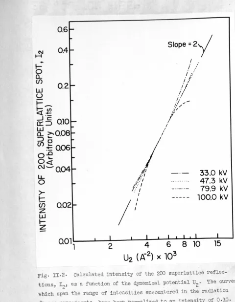
When the ordered compound is examined for extended periods of time in a 100 kV electron microscope, it is observed that the material becomes slowly disordered. Several possible explanations were considered for this effect, but it has been concluded that the disordering results from the displacement of carbon atoms by impinging electrons (i.e., by radiation damage). To determine the magnitude of the displacement threshold, studies have been rrade of the dis-ordering rate under electron bombardment at energies from 33 keV to 100 keV, using a Faraday cup to measure superlattice spot inten-sities. The results have been compared with a theory for the damage process, from which it is concluded that the displacement energy of carbon atoms in V6C5 is
5.4
eVeThis value is unexpectedly low in comparison with the values that have been reported for most other materials, but it is
interatomic distances through the lattice to a position at which the vacancy-interstitial pair is stable, and (3) form an intersti-tial at the terminal point of the disturbance. calculations show that for most solids, the threshold energy is determined princi-pally by mechanisms (2) and
(3),
but for V6C5 only the first pro-cess is important since a large number of vacant sites are avail-able in the carbon sublattice to accept a displaced atom with the expenditure of very little energy.The fact that
V6P5
can be disordered in si~~ by electron microscope beam bombardment has presented an unusual opportunity to study the effect of electron channelling on radiation da~age rates. It has long been a question whether significantly less damage occurs when a sample to be irradiated by energetic elec-trons is oriented for "anomalous transmission," a phenomenon which is similar to the Borrmann effect for x-rays and to channelling for ion beams , Experiments with ion beams have demonstrated that the damage rate in channelling orientations can be 10 times less than in -random orientations, but no analogous experiments have been performedsmall divergence of the electron microscope beam, the ability to orient the crystal with great precision, and the fact that the full analytical capabilities of the electron microscope can be used to monitor the damage process in V6C5 have now made such an experiment possible.
Finally, studies have been made of the re-ordering kinetics of radiation damaged V6C5 to determine the activation energy for carbon diffusion. These measurements, which have been made in a
o
temperature range about 1000 C below that for which previous values have been obtained, have important implications for the mechanical properties of V6C5 and provide an explanation for the extremely
CHAPl'ER 1 1.1 CHAPTER 2 2.1 2.2 CR.~Pl'ER 4
4.1
. PARr I
nrrRODUC'rION
A brief review of ordering in the "cubic" carbides
Scope of the present work
REFERENCES
EXPERTIM-I"TAL DEl'A ILS Crystal growth
Preparation of thin foils
REFERENCES
EVIDENCE FOR ORDERJNG
Observations with reflected polarized light
Observations by electron microscopy The superlattice unit cell
REl!'ERENCES
NATURE OF THE ORDERJNG
Nuclear magnetic resonance of V5l in ,VCO.84
Proposed crystal structure of VCO.84
(V6C5)
PARI' II
RADIAT ION DAMAGE OF V6C5 BY ELECTRON MICROSCOPE
BEAM BOMBA RDlOOfr
IATTICE DISORDERING BY ELECTRON
BOMBARDMENT
Evidence for disordering in VhC5 during electron bombardment Theoretical considerations for
disordering by electron bombard-ment
5.2.1 The displacement cross-section CHAPl'ER5
5.2.2 Seconda~J displacements REFERENCES CHAPl'ER6
6.1
6.2
CHAPI'ER 7 CHAPI'ER 8 8.1A MODEL FOR THE DISORDERING The displacement process The rate of disordering REFERENCES
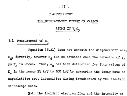
THE DISPIACEMENT ENERGY OF CARBON ATOMS IN V6C5
Measurement of Ed Discussion of results REFERENCES
FU'RlHER RADIATION DAMAGE STUDIES
Search for effect of electron channel-ling on damage rates in V6C5 Diffusion of carbon in V6C5
AN OVERVIEW
Page Number
CHAPl'ER9 GENERAL DISCUSSION AND SUHMARY
9·1 Discussion 98
9·2
Summary 115RE:FEmNCES 120
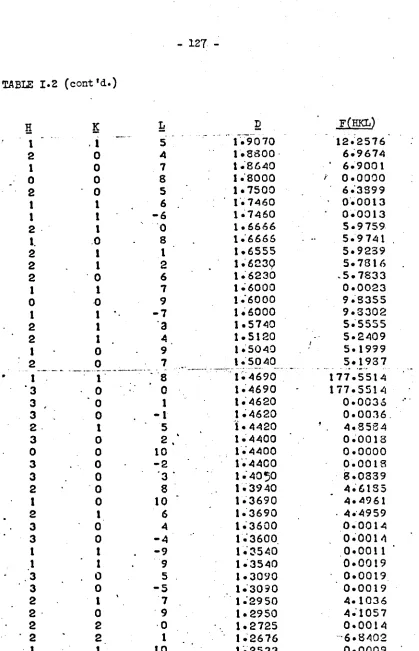
APPENDIX I CRYsrALLOGRAPHIC DATA FOR V6C5 123
APPENDIX II RELATIONSHIP BErWEEN THE Im'ENSITi OF .1\ SUPERIA'l'I'ICE DIF'JrRACTION SFOT
AND rrs STRUCTURE FACTOR 131
APmmIX III BIBLIOGRAPHY 136
1.1 A brief review of ordering in the "cubic" carbides
The transition metal carbides belong to the class of refrac-
.
tory hard metals that are formed by reacting a Group IV, V, or VI transition element with one of the small nonmetals such as boron,•
carbon, nitrogen, or oxygen. The unusual properties of these com-pounds have been discussed by Schwarzkopf and Kieffer,(l) Kieffer and Benesovsky,(2) storms,(3) GOldScr~dt,(4) H0110x,(5) and Wi11iams,(6) but generally they are characterized by their high
melting points, extreme hardness, metallic reflectivity, and metallic electrical conductivities that are comparab l,eto those of their
parent metals. Within varying composition limits all of the Group IV and V carbides exhibit a nominally cubic structure in which the metal atoms occupy close packed fcc positions with the nonmetal atoms arranged in the octahedral interstices. (1-3) This structure is isomorphous with that of NaC1, but the metallic nature of the carbides'suggests that it is more appropriate to consider them as
.fcc metals which are stabilized by the presence of carbon atoms.(7) • This interpretation has received. support from the description of
(8-10) ( )
bonding in TiC and VC derived by Lye to be discussed below
. (11)
2
-of TiC, (111) (110), corresponds to that -of fcc metals, rather than to that of NaCl, in which slip on (111) planes is inhibited by the
ionic character of its bonding.
studies of the phase equilibrium in the MC carbides have
shown that they retain their stabilized fcc structure over a relatively wide phase field. For exampie, storms(3) phase diagram for the
titanium-carbon system indicates that the range of homogeneity of TiC , where x is the carbon-to-metal atom ratio, extends from x = 0.53
x
to 0.96. The range for VC is somewhat more limited because of the x
presence of a.V2C phase at the low carbon end and a broad two phase VC + C region at high carbon concentrations, but as indicated by Adelsberg and cadoff,(12) the carbon-to-metal ra~io can vary from x = 0.67 to 0.89.
tre(8-10) has proposed an explanation for the wide homo-geneity range of VC and TiC which is based upon the current under-standing of their unusual electronic structure. According to the results of his semi-empirical LCAO band structure calculations, the outer electrons of the six metal atoms surrounding a carbon atom . overlap onto the carbon atom site depositing a negative charge there.
bands associated with the metal atoms. To minimize their energy these electrons are redistributed into the lOwer lying bands, mostly 3d bands, where they occupy normally vacant states. Since these
states make important co~tributions to the total cohesive energy,(9) their degree of occupancy plays a major role in determining the phase changes which accompany variations in stoichiometry.
In VC thosed-states whose orbitals overlap in a bonding configuration become completely filled when the carbon-to-metal
atom ratio is approximately 0.91.(13) Beyond this composition, addi-tional carbon atoms contribute electrons to antibonding d-states, but to avoid this it might be expected that carbon would segregate to a more energetically favorable form. The presence of a transformation from single phase VC to VC + C at a carbon-to-metal atom ratio of . approximately 0.89(12) suggests that the position of the upper phase boundary in VC can be accounted for by the tendency to avoid the occupation of antibonding states.
No such restriction is imposed upon the carbon concentration in TiC because the bonding states are not completely filled even at
.
the stoichiometric limit.(13) This slight difference in theelec-tronic structure of TiC, relative to that of VC, is reflected in the ability of TiC to attain a carbon-to-metal atom ratio which is very close to unity.(3) Whether TiC can be prepared at precisely the
4
-stoichiometric composition remains a controversial qUest10n,(3) but in spite of this uncertainty, it appears that the position of the upper phase boundaries for these materials can be explained in a semi-quantitative manner on the basis of Lye's model for their elec-tronic structure.
When the carbon concentration is decreased to a value well below that at the upper phase boundary, the number of electrons
asso-ciated with metal atom states diminishes toward the normal value for the pure metal. In TiC the titanium atoms achieve their normal com-plement of electrons at a carbon-ta-metal atom ratio of 0.6 and, as suggested by Lye,(B) it is not unreasonable to expect a phase trans-formation to the usual hcp structure at this composition. Support for this description of the behavior of TiC in terms of the occupa-tion of metal atom electronic states is obtained from storrr~(3) phase diagram which places the phase boundary between TiC and ~ - Ti + TiC at x
=
0.63. Similar arguments undoubtedly apply to other carbides, but in some cases, e.g. VC, the situation is complicated by the pre-sence of other phases. These phases may also be understood in terms of the electronic structure, but further discussion of this question will be deferred until Chapter Nine.On the basis of these considerations, the large breadth of the homogeneity range and the significant deviation of the upper phase boundary from integral stoichiometry are readily explained as
intrinsic features of the carbides. Thus, the electronic structure of these compounds permits and sometimes enforces the presence of an un-usually high (carbon) vacancy concentration, which can be orders of magnitude greater than that established normally by thermal equilibriltm requirements. No stuqy of the carbides would be complete unless the behavior imposed by such a large vacancy content were understood, and,
in particular, it would seem reasonable to expect that some physical and mechanical properties would be sensitive to the degree of order exhibited by the carbon atoms and carbon vacancies on their sublattice.
Among the first reported attempts to look for ordering in non-stoichiometric carbides was the work of Gorblli~ovet al. in
1961.(14) Using neutron diffraction, to take ad'rantage of the rela-tively large scattering cross-section of carbon atoms for this type of radiation, they concluded that the vacancies are distributed randomly in TiC throughout the entire composition range. Later,
x
similar experiments by Goretzki(15) indicated that carbon vacancy ordering does occur in TiC but only in the composition range x
=
0.64 to x=
0.72. Goretzki rationalized these somewhat divergent results by claiming that Gorbunov et al. had not examined material of the appropriate compositions.Neutron diffraction techniques have also been applied to the study of NbCO•75 and TaCO•75 by Zubkov et al.(16) who observed
6
-sublattice. unfortunately, these studies were restricted to the one composition, x = 0.75, since the authors were attempting to demonstrate a particular point derived from energy considerations based on Bilz's(11) electronic band structure calculations, namely, that nearest neighbor carbon vacanc~ pairs should be unstable in the Group V carbides. (It can be shown(16) that the only way to avoid
such pairs in an MC carbide having a carbon-to-metal ratio x = 0.75, is through ordering of the vacancies.) Thus, the degree of order exhibited throughout the remainder of the MC phase field for these materials is uncertain.
Conclusive evidence for ordering in vanadium carbide was reported in 1966 by de Novion, Lorenzelli and costa,(18) who observed ~eak 6uperlattice lines in Debye-Scherer X-ray patterns of
ve
O.8B
powders prepared by heating the metal hydride in contact with gra-phite. They attributed the supplementary lines to an ordered dis-tribution of carbon vacancies, and, from an analysis of the observed systematic extinctions, concluded that VCO.88 (v8C7) should be des-cribed in terms of a cubic unit cell with symmetry p4332 or p4l32
o
and a parameter, a
=
8'33 A, t~ice that of the NaCl cell. In asso-ociated work, Froid~vaux and Rossier(19) were able to confirm the .vacancy ordering described by de Novion et al.(18) by investigating
the nuclear magnetic resonance (m{R) of the principal vanadium
i30-.
51
tape, V 1in VC specimens. The resonance spectra exhibited a line
splitting characteristic of nuclei with a quadrupole moment that are situated in a non-cubic local environment. This observation was not unexpected since missing carbon atoms destroy the local
cubic symmetry; however Froidevaux and Rossier were able to asso-ciate specific peaks in the spectra with nuclei in sites having 0,1,2, and 3 nearest neighbor carbon vacancies. The relative popu-latlon of these sites differed substantially from that expected from a random distribution of vacancies, and on this basis they concluded that the carbon atoms were arranged in an ordered manner.
Although the presence of long range order in VCO.88 was definitely established trJough combined X-ray diffraction and NNE measurements, the situation in material having a lower carbon con-centration was somewhat less clear. According to de Novion et al.,(lS) the cubic superlattice X-ray line intensities, which are functions of the long range order parameter, stufered a marked decrease as the carbon concentration was reduced below that of VSC7. On the other hand, the experimental distribution of vanadium sites having 0,1,2 and 3 nearest neighbor carbon vacancies (as determined by
lThm(19» differed substantially from a random distribution throughout the entire composition range. Since the NMR techni~ue does not, in itself, readily distinguish between long and short range order, these apparently divergent results could be rationalized if it were assumed
8
-that the distribution of additional vacancies in the low carbon
material exhibited short range order only. In the following chapters, however, it will be shown that the situation is much more complex than this interpretation suggests and that another ordered struc-ture, which is not readily detected by X-ray diffraction, ferms when the carbon concentration is slightly below that of V8C7·
1.2 Scope of the present work
Transmission electron microscopy and selected area dif-fraction have, for many years, been successfully applied to the
study of ordering in metal alloys but only recently have they been shown to be useful for studying ordered interstitial compolli1ds. For example, the power of the techniques for sensing relatively
light elements, even when they are present in a host matrix of heavier atoms, is illustrated by the work of Van Landuyt et al.(20) who investigated the distribution of (oxygen) interstitials in Nb. These authors observed supplementary electron diffraction spots and a domain structure in vacuum annealed Nb which they attributed to
ordering of the interstitial oxygen atoms. From an analysis of the diffra~tion data, a unit cell having monoclinic s~etry was deduced for the super'LattLce and the domain structure was explained in terms of six equivalent orientations of the ordered lattice with respect to that of the host metal.
Until the present study these techniques had not been applied to the carbides because the materials generally available were either powders, sintered compacts, or small crystals that were not suitable for obtaining thinned sections. HOwever, the successful production of large single crystals of the carbides in a crystal growing program associated with this investigation has made such a study feasible. (2l)
In a sense the scope of this work must be considered some-what limited since only one composition of vanadium carbide, VCO.84'
has been studied in detail. However, the impetus for the investiga-tion was not simply to collect data on a large number of ~terials and compositions but, rather, its aim was to obtain an improved understanding of the unusual properties that make the transition metal carbides potent1al~ useful materials for future technology. Thus, an attempt has been made to fully characterize the structure
of one particular ordered compound, V6C5,in the hope that quch information might contribute to an understanding of the driving forces, 1.e. the electronic interactions, which establish the order. Moreover, since the long range ordering observed in V6C5must be
expected to modify its dislocation structure and thus influence the mobility of these dislocations, it was hoped that a knowledge
/
w
-of the structure would also contribute to an understanding of the mechanical behavior. This investigation will be described in Part I.
During the course of the electron microscope studies it be-came evident that the superlattice and domain structure exhibited
by the ordered compound V6C5 were being disrupted by electron micro-scope beam bombardment. This effect is interpreted as arising be-cause carbon atoms are displaced by the incident electrons. However, the conclusion that a material as refractory as vanadium carbide can
be damaged by relatively low energy electrons is somewhat surprising and has important implicaticns, not only for the general problem of
radiation damage in solids, but also for the stability of various
refractory materials employed in nuclear reactor technology (e.g.
actinide series carbides and nitrides). Accordingly, the disorder-ing phencmenon has been subjected to a detailed analysis (described
in Part II) in order to obtain a quantitative value for the
thres-hold energy required to displace a carbon atom in V6C5'
REnRENCES
1. p. Schwartzkopf and R. Kieffer, "Refractory Hard Metals," (The Macmillan Co., NewYork, 1958).
2. R. Kieffer and F. Benesovsky, ''Hartstoffe,'' (Springer-Verlag, Vienna, 1963).
3. E. K. storms, '~he Refractory Carbides," (Academic Press, NewYork, 1967).
4. H. J. Goldschmidt, "Interstitial Alloys," (Plenum Press, NewYork, 1967).
5.
G. E. Ho11ox, Mat. Science Eng., ~, 121 (1968).6.
w.
S. Williams, Science, 152, 34
(1966).7. D. A. Robins, POwderMetallurgy, No. 1/2, 172 (1958).
8. R. G. Lye and E. M. Logothetis, Phys. Rev., 147, 622 (1966). 9. R. G. Lye, in "Atomic and Electronic Structure of Metals,"
(ASM,Cleveland, OhiO, 1967).
10. R. G. L.,ve, G. E. Hol1ox, and J. D. Venables, in "Anisotropy in Single Crystal Refractory Compounds," Vol. 2, edt F. W. Vahldiek and S. A. Mersol, (Plenum Press, NewYork, 1968), p.
445.
11.
w.
S· Williams ~nd R. D. Schaal, J. Appl. Phys.,n,
955 (1962). 12. L. M. Ade1sberg and L. H. cadoff, J. Am. Ceram- sce.,L!,
213(1968) •
12
-14. N. S. Gorbunov, N. A. Shishakov, and C. G. Saidkov, Izv. Akad. Nauk. SSSR, 11, 2093 (1961).
15· H· Goretzki, Phys. Stat. Sol., 20, K141 (1967).
16. V. G· Zubkov, L. B. Dubrovskaya, p. V. Ge1'd, V. A. Tskhai, and y. A. Dorafeev, Dokl. Akad. Nauk. SSSR, 184, 874 (1969). 17· H. Bilz, Z. Physik, 153, 338 (1958).
18.
c.
H. de Novion, R. Lorzene11i, and p. Costa, Compt. Rend., 263, 775 (1966).19· D. Froidevaux and D. Rossier, J. Phys. Chem. Solids, 28, 1197 (1967) •
20. J. Van Landuyt, R. Gevers, end S. Amelinckx, Fhys. Stat. Sol.,
.!3.,
467 (1966).21. W. Precht and G. E· Ho1lox, J. Crystal Growth,
3-4,
818 (1968).CHAPI'ER TWO EXPERJMENTAL DEI'ATIS
2.1 Crystal growth
The vanadium carbide single crystals employed in this study were grown by W. Precht of RIAS, who employed the floating zone
technique described by Precht and Hollox. (1) starting rods,' 18 cm long and 2 cm in cllameter,were prepared by Lsoat.at.Lcpressing to 50,000 psi an aggregate containing VCO•92 pOwders (supplied by Con-solidated Astrona1ltics), small additions of vanadium metal powder to achieve the desired carbon-to-metal ratio, and 0.5 weight percent of a binder consisting of
5i
polyvinyl alcohol in distilled water. After sintering at l7000C fer 2 hours in a vacuum of 10-5 Torr, therods were diamcnd ground to a constant diameter, see fig. 2.l(a), to ensure that a uniform molten zone could be maintained during crystal
grOwth-The crystal growing apparatus, fig. 2-2 and 2-3, is conven-tional except for the provision of a heavy stainless steel outer can that allows the furnace chamber to be pressurized with 10 atmospheres of helium. ~nis inert gas blanket is required to reduce the preferen-tial volatilization of vanadium which occurs at rapid rates above 2000oC- The sintered rod is held between two water cooled copper chucks which can be translated up or down to move the work past the
a
b
f' "
~O
Fig. 2.1. Single ~rystals of VC
o
.84
were prepared fer this in-vestigation by passing a molten zone along a sintered rod such as that shawn in Ca). The zone melted section, s11O\·;nin Cb), is polycrystalline near the starting end (right side of figure) but is single crystalline for the last 3~}of its length.SLIDING SEAL
TANTALUM RADIATION SHIELDS
BASEPLATE OF
PRESSURE CHAMBER
SPECIMEN
o
o .-.
R.F. COILo
GRAPHITE SUSCEPTOR
TOP PLATE OF
PRESSURE CHAMBER
WATER COOLED
COPPER
Fig. 2.3. Internal construction of pressurized crystal growing chamber. (After Precht and Hollox(l).)
GRAPHITE HOLDER
the three-turn r.f. heater coil. The upper chuck can be translated independently of the lower one to compensate for density changes and to help maintain the stability of the zone, whereas the lOwer chuck
can be rotated to compensate for any slight deviations from axial symmetry exhibited by the work coil. A 50 kVA r.f. generator opera-ting near half power was sufficient to melt a stable zone approximately 1 cm high in the sintered rod. Best results were obtained when this zone was moved at a rate of 0.3 to 0.6 c~hr from the bottom to the top of the rod, the freshly grown crystal passing directly into a gra-phite susceptor afterheater to reduce the~l shock cracking.
Single crystals of a desired carbon-to-metal ratio may be grown in this manner by properly adjusting the composition of the
sintered rod, but as noted by Precht and HOllox,(l) due considera-tion must be 'given to the phase diagram,(2) fig. 2.4, in order to ensure a uniform composition along the entire length of crystal. For example, it was observed by these authors that when a rod having a nominal composition VCO•75 is zone melted, the first zone to freeze has a composition close to VCO•82' consistent with the separation between the liquidus and solidus lines in this region of the phase diagram. This situa~ion leads to composition gradients along the length of the rod which persist until the composition of the liquid zone approaches a carbon-to-metal atom ratio x
=
0.62 by zone re-fining action. It was demonstrated, hOwever, that zone levellingLIQUID
..
VC+ C
(,)
o
W
0:::
:::::>
~
a::
w
~
2000
w
I-0.4
0.6
0.8
10
1.2
C/V ATOM RATIO
Fig. 2.4. Vanadium-carbon phase diagram- (After Adelsberg and
C
adorr(2).)
conditions may be achieved at the start of crystal growth by
incor-porating an additional section into the lower end of the rod that
has a composition close to VCO.62 and a volume equal to that of the
molten zone.
For the present study, single crystals having a
carbon-to-meta 1 ratio close to the integral composition V6C5 'Were desired and starting rods 'Were made by adding 10'/0by weight of vanadium metal to the VCO•92 powder. Because this composition lies close to the melting
point maximum 'Where the liquidus and solidus lines join, it 'Was not necessary to take precuations against any zene refining action. Thus,
in this case, zone levelling starts 'When the initial molten zone is
formed and continu€'!athroughout the remaindar of the traverse. A V6~ crystal sim1lar to these employed in this investiga-tion is shown in fig. 2.1(b). Typically, the zone melted section
is polycrystalline and fine grained at the starting end, but, because
preferential growth of one grain occurs during the freezing process, the last
3/4
of the rod is generally single crystal. Since the rods are not ~ormally seeded, the growth directions do not usually lieparallel to low index crystallographic axes. However, this presents
no problem since specific sample orientations may be readily obtained
16
-Chemical analysis, emission spectroscopy, and lattice para-meter measurements based on storm's(3) data have been used to
characterize the crystals, Table 2.1. The carbon-to-metal ratios determined from chemical analysis (by a commercial analytical labora-tory) are consistent with the more accurate results obtained by NMR measurements· that will be described in Chapter 4, but disagree
slightly with the values obtained by lattice parameter measurements. This suggests that the latter method of specifying the composition may be subject to a systematic error of approximately 0.01 in the values of x as first noted by Lowndes et al.(4)
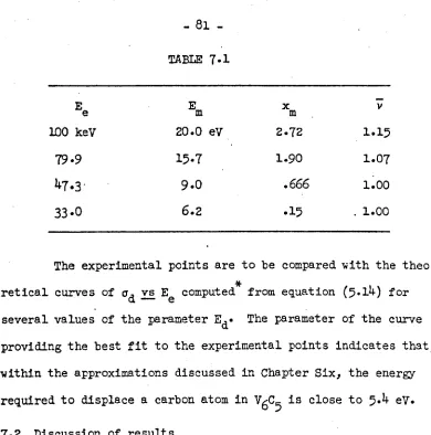
TABLE 2.1
COMPOSITION OF V6C5 SINGLE CRYSTALS USED IN THIS INVEffi1IGATION
carbon-to-metal atom ratio:
by chemical analysis --- x
=
0.84 by lattice parameter --- x=
0.851 by NMR --- x=
0.838 Impurity content:Element
by spectrographic analysis Cr
Fe
Mo
Ti Zr by chemical analysis
Thin foils for the transmission electron microscope studies were obtained by jet etching small disks of V6C5 with a 20% sulphuric acid - 80~ methanol solution, followed by electrolytic polishing in the same solution. To prepare samples for thinning, the single crystal
boules were oriented by standard Laue X-ray d~ffraction methods and sectioned with a diamond saw into O.25mm thick slices having either
(lOa}, (110}, or (111) faces. Disks, 3mm in diameter, were cut from
the slices using an ultrasonic impact cutter and then mechanically polished with 3~ diamond paste in order to remove all coarse scratches} saw marks, etc.
The thinning apparatus, fig. 2.5 and 2.6, includes provisions for both jet etching and electrolytic polishing in one unit. In the
jet operation a stream of electrolyte is directed against both sides
of the sample by two jet nozzles made of l~~ inside diameter stain-less steel tubing. The nozzles are made cathodic with respect to
the sample by approximately 6-8 volts, the potential being adjustei
to maintain a total current of 350 rna for optimum polishing
C'ondi-tions. Once well defined craters are formed on both sides of the
disk, the sample is transferred to the electrolytic polishing bath
where it is thinned to breakthrough using a current of 150 rna. The hole produced during polishing is kept small by switching off the
the sample is thinned by the jet technique to produce a convex profile near the center of the disk. The sample is then polished electroly-tically until perforation occurs) at which time the current is shut off. The optical system provides a means of d~termining the instant of breakthrough.
18
-current supply at the instant light is observed through the light pipe arrangement shown in fig. 2.6.
Samples prepared in this manner fit directly into the elec-tron microscope holder without the need for further support. Further-more, because they exhibit large transparent areas and are inherently rigid, the foils are suitable for both the general contrast and dif-fraction experiments discussed in part I, as well as the radiation
damage experiments discussed in Part II, which place stringent require-ments upon sample stability.
REFERENCES
1. W. Precht and G. E. Hollox, J. Crystal Growth, ~, 818 (1968). 2. L. M· Ade1sberg and L. H. cadotf, J. Am. Ceram- Soc.,
2!,
213(1968) •
3. E. K. Storms, ''The Ref'ract ory carbides," (Academic Press, New York,1967) p. 51.
20
-CHAPTER THREE
EVIDENCE FOR ORDERING
-:---3.1 Obs~rvations with reflected Eolar1zed ligh~
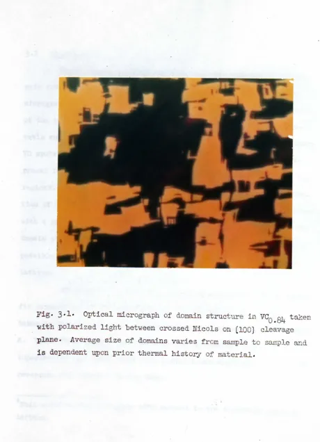
When a cleaved, or highly polished face of single crystal VCO.84 is examined in reflected polarized white light, a domain type of substructure similar to that shown in fig.'3 ..l, is observed. Be-cause matching freshly cleaved faces exhibit identical patterns which remain unchanged indefinitely at room temperature, the coloration can be attributed to optical anisotropy of the crystal rather than to a surface film. Thus the substructure is visible because each dona In exhibits a color, due to birefringence, which contrasts with that of n•.dghboring domains.
The presence of birefringence is surprising since vanadiTh~ carbide previously had been considered to be a cubic, isotropic
material. Also surprising is the presence of domains, which have not been observed in any of the mor e widely stu.died, cubic transition
metal carbides. It will be shown in the subsequent sections, how-ever, that these unexpected findings may be understood in terms of the non-cubic superlattice which forms in VCO.84 as a consequence of long range vacancy ordering.
plane- Average size of domains varies from sample to sample and
[image:41.502.16.476.16.652.2]21
-Figure 3·2 is a transmission electron micrograph of the do-main substructure as observed in a (100) fOil.* Accompanying the micrograph are two selected area diffraction patterns, one from each of the two domains marked A and B in the figure. Each pattern re-veals supplementary, or superlattice spots in addition to the primary VC spots. The primary spot pattern w!lichmaps out the (100) reci-procal lattice plane, maintains an equivalent orientation in the two regions. The supplementary spot pattern, hOwever, undergoes a
rota-o
tion of
90
between domains A and B. Thus, each domain is associated with a specific orientation of the superlattice and, apparently, the domain structure results because the superlattice can assume several possible orientations within the nominally cubic vanadium carbide lattice.To demonstrate that each domain is associated with a speci-fic orientation of the superlattice, the micrograph in fig. 3.2 was taken in dark field, using a superlattice spot associated with domain A. Under these conditions, the domain at B remained dark. When a
superlattice spot associated with domain B was employed, the contrast reversed, and domain·A became dark.
*Foil orientations are given with respect to the nominally cubic VC lattice.
tion patterns obtained from each of the two domains, A and B, demon-strate that primary VC pattern maintains equivalent orientation in two regions, but superlattice pattern undergoes
90
0rotation. plane offoil is '(lOa).
22
-Although the boundary walls between domains do not lie along well defined crystallographic planes, they do exhibit a ten-dency to lie parallel to (lOO} and (110}planes, as shawn in fig. 3.3. From the nature of the contrast (asymmetrical in bright field), it
is concluded that the boundaries at A and Bare 5 interfaces(l) that are similar to those observed in Nb by Van Landuyt et al. (2) The un-usual contrast effects which have been observed within the do~ains
(e.g., the mottled contrast of domain A in fig. 3.2 and the periodic fringes in fig. 3.3) are not completely understood but it 1s possible they may be a conse~uence of the unusual crystallographic structure of this material, as will be discussed in Chapter Four.
3.3 The sUTIerlattice unit cell
For ~he purpose of determining the symmetry and dimensions of the superlattice unit cell, selected area diffraction patterns were obtained from several foil orientations. A schematic diagram of all the observed diffraction patterns obtained from individual domains in (lOO), (110)and (111)foils is presented in fig.
3·4.
In some foils, the patterns differ only with regard to the orienta-tion of the superlattice spots relative to the primary spots. In other foils, superlattice patterns exhibiting different symmetry are observed. In all foils, however, the primary spot pattern remains essentially undeviated througho~t the specimen, and to a firstapproxi-,
mation it exhibits the s~~~etry and dimensions of a cubic structure o
Fig. 3.3. Bright field transmission electron micrograph of 8. domain
in (100) foil. Domain walls do not lie along well defined crystallo-graphic planes, but those at A and B are roughly parallel to a CllO} plane, whereas the wall at C is roughly parallel to a (lOO} plane. Fringe contrast of boundaries at A and B is asymmetrical indicating
they are 5 interfaces.
(lOO)
FOIL 002 022•
•
•
•
•
•
•
• @ •
•
•
•
•
• • •
• •
•
•
•
• PRIMARY LATTICE • SUPERLATTICE•
•
• @ •
•
•
•
•
•
•
•
002•
•
••
•
••
•
•
•• ••
•
•
• • • .111
• •
•• •
•(110)
••
• @ •••
_
•
.@
••
•
•
@.
•
•
•• •• 220 •
••
•• •
FOIL
••
••• ••
•••••••
•
•
•
•
022
•
•
•
•
•••••
••
•
•
•
•
•
•
•
•
•
•
•
•
•
•
(111 )
•
•
•
•
•
•
•
•
•
•
••• @ •••
•
@•
•
@•
• •• @ •••FOIL 220
•
•
•
•
•
•••••
•
•
•
•
• • •
•
•
••••••
•
•
• •
•
•••••
a
b
c
d
The symmetry of the superlattice unit cell may be deduced directly from fig. 3.4. The superlattice spots in pattern (lll)d exhibit 6-fold symmetry, which indicates the presence of either a 3- or 6-fold axis in the unit ce Ll,, (A 3-fold axis in real space
will give rise to a 6-fold symmetrical electron diffraction pattern because of the presence of positive and negative reflections (3).) The
unit cell must, therefore, belong to either the hexagonal* or cubic crystal class because only these possess symmetry of this type. The orientation of the superlatti~e pattern with respect to the
primary pattern dictates that the super lattice should give rise to a cubic pattern in (100) foils if its unit cell were cubIc , Since such a pattern is not observed in this foil orientation, it is con-cluded that the unit cell must be hexagonal.
The dimensions of the unit cell can be obtained from the
d-spacings which are associated with the various superlattice
reflec-tions observed in fig. 3.4. A summary of several important d-spacings obtained from the electron diffraction patterns is presented in
Table 3.1. Included in the table are d-spacings obtained from twa
~eak superlattice lines that have been observed in X-ray diffraction
pOwder patterns from crushed single crystal samples. The X-ray
dif-fraction data serve as a check on the electron diffraction d-values
24
-and also demonstrate that the important low index reflections,
cor-o 0
responding to d
=
4.80 A and 4.40 A, are real reflections in theTABLE 3.1
Measured Superlattice d-values calculated
d-values from Hex. Unit cell;
0 0
Electron X-Ray a = 5.09 A, c = 14.40 A
Diff Diff
d HKL
0 0 0
4.80 A 4.80 A 4.80 A 003
4.40 4.42 4.42 100
3·77 3·79 102
2·78 2·79 104
2.40 2.40 006
2.21 2.20 200
electron diffraction patterns and do not arise, for example, be-cause of multiple electron scattering. By using a Bunn chart for hexagonal structures, the parameters of the unit cell were found to be a
=
5.092
and c = 14.40j.
The orientation of the superlattice unit cell with res-pect to the primary unit cell is as follows:
(OOl}SL
II
(lll}PL.The length of the c-axis corresponds to six complete (ill}.layers of atoms in the cubic lattice, and the length of the a-axis corres-ponds to the carbon-carbon (or metal-metal) atom spacing in the (112) direction of the primary cell.
FUrther analysis of the patterns shown in fig.
3.4
indi-cates that four orientations are possible for the superlattice, corresponding to the alignment of the c-axis parallel to anyone of the four equivalent (111) directions in the primary cell. Only two distinguishable diffraction patterns are observed in a(100) foil because the reciprocal lattice projections of two
26
-REFERENCES
.1. R· Gevers, J. Van Landuyt, and S. Ame11nckx, Phys. Stat. Sol., 11, 689 (1965).
2. J. Van Landuyt, R. Gevers, and S. Ame11nckx, Phys. Stat. Sol.,
1:3.,
467 (1966).CHAPI'ER FOUR NATURE OF THE ORDERJlJ'G
_51
*
4.1
Nuclear Magnetic Resonance ofv-
in VCo.84Although the dimensions and symmetry of the super lattice unit cell can be derived from electron diffraction patterns as shown in Chapter 3, these data do not provide a description of the vacancy distribution within the cell. This information, however, can be ob-tained by NMR techniques.
The response of an atom to an oscillating magnetic field depends not only on the intrinsic properties of the atom but also on the local environment in which the atom is situated. For example, a displaced or missing atom destroys the local cubic symmetry in an otherwise perfect cubic ~rystal, and this disrupted symmetry can be expected to result in electric field gradients at the nuclei of atoms surrounding the defect. Such a situation occurs frequently in VC, of course, because the number of carbon atoms present is substantially less than the number of available sites in the carbon sUblattice of this nominally rocksa Lt crystal. Furthermore, the principal vanadium
isotope,
v5
l (- looi abundance), has a nuclear electric quadrupole moment (-0.052 X 10⁻²⁴ cm2),(1) so that the presence of an electric28
-field gradient at the vanadium nucleus modifies the NMR behavior. In particular, the electric field gradient will split the single reson-ance line that is observed when the
v5
1 atom is in a cubic environment into a central component and three pairs of satellite lines (I=
7/2) which are more or less symmetrically disposed about the central line. The central line also will be displaced by an amount which varies in-versely with the strength of the applied dc magnetic field, Ho. Con-sequently, thern~
of VC specimens exhibit complex spectra which can be analyzed to yield information about the distribution of carbon vacancies within the crystal.The VC specimens employed in this study were obtained by crushing the VCO.84 single crystals so that the individual parti-cles were smaller than the skin depth of the r.f. field used. The y5l NMR spectra obtained from the powdered specimens (powder
pat-terns) could be resolved into central components, shown in fig. 4.l(a), and a satellite structure, shown in fig. 4.l(b).
Although some aspects of the identification require con-firmation, the principle features can be accounted for on the following basis:
3500
Ho(GA~SS)
14 -,
Vo+ V
1---,---v,p-3460 3480
(b)
3520 3540
L- ....1.... ~I--_I_---'---....J----
---,
,
,
10,200 10,400 10,600 10,800
Ho(GAUSS)
Fig.
4.1.
Nuclear magnetic resonance curves of V51 nuclei in VCa
Rh obtained at 77°K. The central resonance, shown in (a}, was separated "into its twa components, Va and Vl, by fitting a Gaussian line and a29
-*
A single line, VO' relatively weak and narrow is observed, with a width of approximately 10 gauss, almost indepen-dent of the strength of the dc magnetic field. This res9nance is attributed to V5l atoms in a nearly perfect cubic environment, i.e. the vanadium atoms contributing to this spectrum must have no vacan-cies in the nearest shell of carbon atom neighbors. The line is
displaced to the high field side of the resonance of an isolated
.v5
l atom by an amount equi~alent to a negative Knight shift of0.32%. Close examination of the spectrum indicates, however, that this resonance is split and broadened by quadrupolar interactions, but only weakly. Two feeble lines,
Vo '
n have been tentativelyassigned to the satellite structure, and their splitting is consis-~
tent with the small quadrupolar broadening
«
4 gauss at Ho=
3000 gauss) beyond the calcu~ated dipolar breadth (~ 7 gauss) of the cen-tral line.(2) A strong broad resonance, Vl, is observed which
com-1 2
prises two spectra, Vl and V1 ' i.e. the central quadrupolar
broadened line has twa components (not resolved in the figure), and associated with them are twa sets of satellite lines. These twa
re-sonances include by far the larger fraction of the
v5
l nuclei detec-ted in the spectrum. The Larmor frequencies of both components are displaced from the resonance of an isolated atom by the same amount, corresponding to a negative Knight shift of 0.13i.The central line has an extrapolated dipolar width near
7
gauss, and additional quadrupolar broadening (proportional to l/H )o that is consistent with the average of the separations of the two
sets of satellite lines (v ~ 280 kHz). This broadening and splitting
q
of the resonance indicates the presence of strong electric field gradients at the
v5
l nuclei involved. The principal component of this gradient is attributed to the presence of a single vacancy in the nearest neighbor shell of carbon atoms surrounding these nuclei,in agreement with the assignment made by Froidevaux and Rossier(2) for a similar.resonance observed in their NMR studies of VC·
31
-indicate a displacement of the resonance to the high field side. The magnitude of the Knight shift cannot be measured accurately for this series, but it is negative and approximately equal to the shifts of the lines discussed in (2). The satellite splitting of this series is larger than for the spectra discussed in (2), and thus corresponds to an even larger electric field gradient at the y5l nuclei inyolved. For reasons to be discussed later, this spec-trum is attributed to y5l nuclei with one carbon vacancy in their nearest neighbor shell, but with ~9 vacancies in the next nearest neighbor shell of carbon atoms.
According to the present analysis of the M{R spectra, almost all of the vanadium atoms are on Vl sites (with one carbon vacancy in the nearest neighbor shell), as might be expected from the fact that the composition of the VCO•84 material studied is close to the integral composition
V6C5.
Only a small fraction of the vanadium atoms are onVo
sites (with no carbon vacancies in the nearest neighbor shell). The integrated intensities, IO and Il, of the central components of the spectra associated with these sites are in the ratio rolrl=
0.035.
Because each carbon vacancy in the lattice has six vanadium atoms surrounding it, the addition of a carbon atom into a vacant site would convert all six of the neighbor-ing vanadium sites toVo
sites. Thus, because most of the y5l atomsappear to occupy Vl sites, the ratio ~Il
=
3.5% implies that the carbon/metal atom ratio in the vanadium carbide unde~ study exceeds that of V6C5 by approximately 0.035/6 ~ 0.5%. That is, the NMR spectra indicate that the composition of this vanadium carbide isVCO•838' in good agreement with the results of chemical analysis (VCO
.84)'
Table 2.1.The conclusion that all but a very small fraction of the y5l nuclei in vanadium carbide are surrounded by precisely five
carbon atoms in the nearest neighbor shell, coupled with the elec-tron diffraction data, has allowed a crystal structure to be deduced
for V6C5. The result, which will be described in the next section, provides a reasonable interpretation for the two components of the
Vl spectrum. In the proposed model of V6C5,all the vanadium atoms have one vacancy in the nearest neighbor shell of carbon atoms, but
two-thirds of them have also a single vacancy in the next nearest
neighbor shell, whereas one-third have two vacancies in this shell. The geometries of these two inequivalent sites are illustrated in
1 2
·fig. 4.2. Because the intensities of the Vl and Vl spectra are 1
also in the ratio 2:1, the Vl spectrum can be associated with vana-2
dium sites of the first kind, and the Vl spectrum with sites of the second kind. Although this assignment is tentative, it is
<ill>
<001>-<
<111>
(110) PLANE
Fig. 4.2. The two types of vanadium atom sites predicted by the pro-posed structure of V6C
5'
Circles are vanadium atoms, shaded squal'e3 represent nearest neighbor carbon vacancies, and open squares are next nearest neighbor carbon vacancies.would convert the six nearest neighbor Vl sites to Vo sites, but the
1 2
Vo sites formed in this way would be of two kinds, Vo and Vo ' cor-responding to the two possible configurations of vacancies in the next nearest neighbor shells of carbon atoms surrounding the original Vl sites. Thus, the small quadrupolar broadening of the Va NMR line can be attributed to electric field gradients caused by second near-est neighbor carbon vacancies.
This extra carbon atom also converts vanadium atom sites
120 1
in its next nearest neighbor shell from Vl and Vl to Vl and Vl sites, respectively. Thus, the presence of an excess of carbon should
a
lead to the ·occurrence of a third NMR Vl spectrum due to Vl sites, which are not present in the perfect
VSC5
crystal. The incompletea
group of satellites labeled Vl in fig. 4.1 is assigned tentatively to this' site.
4.2. Proposed Crystal structure of VCO•84 (V6C5)
Data obtained from electron diffraction,
r~,
and chemical analysis have been employed to deduce the superlattice structure of .VCO.84crystals under the assumption that the vanadium atoms form aonly in that carbon vacancies are distributed in an ordered manner through the carbon lattice.
A model of the proposed structure is shown in fig. 4.3(a). It will be noted that carbon atoms have been removed from certain (lll} carbon planes so that each vacant site is separated by a (112)
0-distance, i.e.
5.09
A, from its six nearest neighbor vacancies in the plane. In this manner, all the vanadium atom sites on the adja-cent (lll} planes are converted from Va to Vl sites. By repeating this construction in every other carbon layer, all the vanadium atom sites are converted to Vl configurations, and the resulting carbo~ metal ratio corresponds to the integral composition V6C5,The symmetry of the resulting carbon lattice is no longer fcc but must be described in terms of an hexagonal unit cell, fig. 4.3(b), whose dimensions, and orientation relative to the vanadium
lattice, are completely consistent with the electron diffraction results. For simplicity, only the vacancy positions have been shown in fig. 4.3(b). However, the complete carbon lattice may be con-structed upon this framework by placing an appropriate grouping of five carbon atoms around each vacancy site. The unit cell contains three screw triads and possesses the symmetry of the hexagonal
(trigonal) class P3l or its enantiomorph, P32' In this figure the
(0'
Vanadium
Atoms o
0= 5.09 A
c
=14.40A
o
Carbon atoms•
ITn
§
Carbon vacancies Inrespective layers
Fig.
4·3·
The structure of V6
C5'
showing: (a) location of ordered carbon atom vacancies (c-axis expanded for clarity), (b) hexa.gonal superlattice formed by vacancy ordering, and (c) projection of super-lattice on a {ill} plane of vanadium atoms. Symmetry of superlattice corresponds to trigonal class P31,or its enantiomorph P32• The material35
-right handed modification,
P31, is shown, however the left handed
form,P32, is an equally probable configuration.
The structure of V~5 may be viewed, therefore, in terms of two interpenetrating lattices; a vanadium atom lattice which, neglecting some distortions that may arise because of the carbon vacancies, is essentially fcc, and an hexagonal superlattice contain-ing all the carbon atoms present. On this basis, it is apparent that the domain structure results because the c-axis of the superlattice can be oriented parallel to any one of the four (lll) directions in the vanadium lattice.
For many purposes, it is convenient to describe the struc-ture in terms of a primary lattice and a su:perlattice. HOwever, this description tends to under-emphasize the anisotropic nature of the material, which leads, for example, to the strong birefringence observed in reflected polarized light. An alternative description that places greater emphasis on the anisotropy of the structure is obtained by considering V6C5 as an hexagonal (trigonal), ordered compound possessing the symmetry
P3l or
P32•
On this basis, a molecule containing six vanadium atoms and five carbon atoms forms the ''buildingblock"· of the structure. The right handed modifica-tion,P31, is illustrated in fig.
4.4.
All the atoms (as well ase
Vanadium
atoms
•
Carbon atoms
D
Carbon
vacancies
*
carbon vacancies) occupy the point position 3(a), with the parameters
listed in Table 4.1. A complete unit cell consists of 9 molecules which are disposed in such a manner that the center of each molecule coincides with a carbon vacancy site. Thus, each of the vacancy
sites shown in fig. 4.3(b) denotes the position of one V~5 molecule, and the complete structure consists of "chains of molecules" that
spiral about a direction parallel to the c-axis of the unit cell, fig.
4.4.
From this point of view, of course, the domain structurearises because the directions of the spiral axes may be different in various regions of the crystal.
By considering V6C5 as an hexagonal compound, the bire-fringence may be rationalized, but the precise orgins of the effect
are not understood. Although the obvious anisotropy is associated
with the carbon lattice, the nominally cubic vanadium lattice may be
distorted by the ordering of the carbon vacancies. Thus, de Novion et al.(3) have noted that a slight displacement (~ 2~) of the vanadium
atoms from their cubic sites is necessary to account for the
inten-sities of the superlattice lines observed by X-ray diffraction in
V8C1' The corresponding displacements have not been determined for
*
Values of the parameters are approximate because possible distor-tions of the parent rocksalt structure have not been included.TABLE4.1
PARAMET~SOF THEATOMS m V6C5
ATOM x y z
Vel) 4/9 -1/9 1/4
V(2) -2/9 -4/9 1/4
V(3) 1/9 2/9 1/4
v(4) -2/9 -1/9 1/12
V(5) 4/9 2/9 1/12
v(6) 1/9 -4/9 1/12
C(l) 1/9 -4/9 1/3
C(2) -2/9 -1/9 1/3
C(3) 4/9 2/9 1/3
c(4) -2/9 2/9 1/6
C(5) 4/9 5/9 1/6
0
1/9 -1/9 1/6V6C5'
but the magnitudes may be similar in the two compounds. Bire-fringence could arise, therefore, from the anisotropy of the carbon lattice, from the associated distortion of the vanadium lattice, or from a combination of both effects. A detailed interpretation must await identification of the electronic excitations that are respon-sible for the optical pro~erties in the virespon-sible region of the spec-trum.4.3.
Discussion of orderigg effectsThis investigation has shown that single crystal vanadium carbide grown from the melt with a carbon-to-metal ratio close to the integral composition V6C5is an ordered hexagonal (trigonal) compound belonging to the space group
P3
1 or P32• This structure is very different from that reported by de Novion et al.(3) for powdered material prepared by reacting the metal hydride with gra-phite. To determine whether the difference is a conse~uence of the two different methods of preparation, single crystal specimens with a composition close to V8C7 have been grown from the melt andexamined by transmission electron microscopy. A detailed interpreta-tion is beyond the scope of this work, but the results indicate that these specimens also exhibit ordering in the carbon sublattice and their electron diffraction patterns are consistent with the cubic
superlattice unit cell proposed by de Novion et al.(3) Accordingly,
it is concluded that at least two superlattice structures are stable within the "cubic" phase field of the vanadium-carbon phase diagram and are established because of differences in composition -- not necessarily because of different methods of preparation.
Although there is no essential disagreement between the two results it should be noted that de Novion et al.(3) did not antici-pate a change in structure as the carbon concentration was decreased below that of V8C7. They observed that the superlattice X-ray lines diminished in intensity with decreasing carbon content and concluded that the distribution of additional vacancies did not exhibit long range order. The weak superlattice X-ray lines derived from the
VSC5
structure were apparently overlooked in their investigation. The proposed structure of V6C5is generally consistent with the results of NMR and electron diffraction, but the fine striations observed under certain reflecting conditions, fig.3.3,
remain to be explained. These striations have not been investigated in detail, however the similarity between their appearance and the contrast effect observed by Pashley and presland(4) in ordered CuAu II sug-gest that they arise from the presence of periodic planar faulting within the crystal.40
-have been determined. In the perfect structure, carbon vacancies are arranged on alternating carbon layers (parallel to the basal plane) in two-dimensional hexagonal nets that are, in turn, sequen-tially positioned so as to define either a right handed or left handed triad screw axis, fig.
4.3.
This sequence is disrupted if one or more of the carbon layers that contain vacancies (C layers)v
is displaced by any vector in the basal plane that connects near-est neighbor carbon atoms. Such displacements do not change the
1 2
Vl or ~l populations and for this'reason it is expected that faults of this type would be low energy configurations with a high probability for forming in the V6C5 structure.
Two basic types of lamellar defects c~n be generated by the indicated displacements. If several successive C layers are
v
-.
all shifted according to the same displacement vectors, an anti-phase region, bounded 'by antianti-phase boundaries (APB's), is formed in the ,manner shown schematically in fig. 4.5(a). If only one out of every three C layers associated with a unit cell is displaced in this
v
(c)
(0)
+
( b)
o
~z ~o
0 ...
a::u
I IJJ
...(f) Z <t
-+--_i_
+
Fig.
4.5.
Schematic representation of twa types of lamellar defects which may occur in V6C"j' In (a) an antiphase section is formed vnenseveral successive C layers (carbon layers that contain vacancies and lie parallel to the basal plane) are displaced by vector
R,
whereR is any vector in the basal plane that connects nearest neighbor car= bon atoms. Depicted in (b) is the change-of handedness, or anti-rotation section t.hat;results when only one out of the three Cv layers associated with a unit cell is displaced by a vector
R.
The basal plane projection (c) illustrates that the crystal axis does not remaincoincident across an anti-rotation boundary, but is displaced by
R/3'
41
-in quartz. The situation is complicated in the present case,
REFERENCES
1. W. J. Childs, Phys. Rev., 156, 71 (1967).
2. D. Froidevaux and D. Rossier, J. Phys. Chem. Solids, ,28, 1197 (1967) •
3.
c.
H. de Novion, R. Lorenze11i, and p. Costa, Compt. Rend., 263, 775 (1966).4.
D. W. Pashley and A.E.B. Pres1and, J. Inst. Metals, S7, 419(1959) •
5. H. Hashimoto, A. Howie, and M. J. Whelan, Proc',Roy. Soc.,
A269,
80 (1962).6. J. van Landuyt, R. Gevers, and S. Ame1inckx, Phys. Stat.
ser., 1,
519 (1964).PART II
BADIA TION DAMAGE OF V6C5 BY ELECTRON MICROSCOPE
CRAPrER FIVE
LATTICE DISORDERING BY ELECTRON
BOMBARDMENT
5·1 Evidence for disordering in V6C5 during electron bombardment
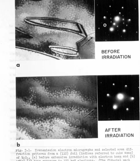
When a sample of the ordered compound V6C5 is examined for extended periods of time in a 100 kV electron microscope, both the super lattice diffraction spots and the domain structure diminish in intensity as illustrated in fig. 5.1. During the initial stages of observation, fig. 5.l(a), the domain structure and superlattice spot pattern remain visible, but after a 10-20 min. exposure to the 100 keV electron beam the domains and supplemental spots disappear en-tirely, fig. 5.l(b), although the intensity of the primary pattern
*
increases slightly. Similar effects are observed at other accel-erating potentials, and in particular, even at the lowest potential employed in this study, 33 kV.
This disordering phenomenon is attributed to the displace-ment of carbon atoms by impinging electrons, and will be subjected to a detailed analysis in subsequent sections. That the effect
*
The increased intensity of the primary pattern is not clearly depicted in fig. 5.l(b) because of the photographic reproduction difficulties, but it is apparent on the microscope viewing screen. This increasea
BEFORE
IRRADIATION
b
AFTER
[image:74.502.6.490.15.570.2]IRRADIATION
Fig. 5.1. Transmission electron micrographs and selected area. dif-fraction patterns from a (110) foil (indices referred to cube axes) of V6C
s'
(a) before extensive irradiation with electron beam and Cb) after l/2 hour exposure to 100 keV electrons. (The fiducial mark indicated by arrows shows that the two micrographs were taken from the same r-egLonv) The domain structure and superlattice spots have disappeared in (b) due to radiation damage by the :tncident electron beam. Quantitative measurements of the rate of disordering were obtained by monitoring the intensity of diffraction spots derived from superlattice planes of the form (2020)· A typir.al spotis due to radiation damage caused by electron bombardment was not obvious immediately, hOwever, and several alternative explanations were explored and dismissed on the basis of the following arguments:
1. The effect is not due to the formation of a surface contamination film. It is observed that the intensity of the super-lattice spots relative to that of the primary spots changes during bombardment, whereas the formation of a contamination film would cause a uniform decrease in the intensity of all the spots. Furthermore, all the present experiments were performed with a highly efficient
cold finger positioned close to the sample area, and no evidence for a contawination film was noted at any time.
consistent with the proposal that the effect is, principally, due to electron bombardment.
3. The effect is not due to thermal disorderin~. Watanabe et al.(2) have demonstrated that the temperature of a metallic foil
o
increased by less than 100 C when it was bombarded with a beam of 100 keV electrons focussed to a 5~ spot at a current density of 2 amp/cm2• The present experiments on vanadium carbide, which also exhibits
metallic thermal conductivity, were performed at current densities between 0.5 amp/cm2 and 1.4 amp/cm2• Thus, the sample temperature
should have been far below the order-disorder transformation tempera-ture of l2500C reported for this material by Hollox and Venables.(3)
4.
The effect is not due to injection of carbon vacancies.Dobson et al.(4) have observed that, under appropriate conditions, vacancies can be injected into specimens of aluminum alloys while they are under observation in the microscope. Thus, it might be argued that, if a specimen of