Temperature Stable Cold Sintered (Bi0.95Li0.05)
(V0.9Mo0.1)O4-Na2Mo2O7 Microwave Dielectric
Composites
WANG, Dawei <http://orcid.org/0000-0001-6957-2494>, ZHANG, Shiyu,
ZHOU, Di, SONG, Kaixin <http://orcid.org/0000-0002-4622-1234>, FETEIRA,
Antonio <http://orcid.org/0000-0001-8151-7009>, VARDAXOGLOU, Yiannis,
WHITTOW, Will, CADMAN, Darren and REANEY, Ian M.
Available from Sheffield Hallam University Research Archive (SHURA) at:
http://shura.shu.ac.uk/24524/
This document is the author deposited version. You are advised to consult the
publisher's version if you wish to cite from it.
Published version
WANG, Dawei, ZHANG, Shiyu, ZHOU, Di, SONG, Kaixin, FETEIRA, Antonio,
VARDAXOGLOU, Yiannis, WHITTOW, Will, CADMAN, Darren and REANEY, Ian M.
(2019). Temperature Stable Cold Sintered (Bi0.95Li0.05)(V0.9Mo0.1)O4-Na2Mo2O7
Microwave Dielectric Composites. Materials, 12 (9).
Copyright and re-use policy
See
http://shura.shu.ac.uk/information.html
materials
Article
Temperature Stable Cold Sintered
(Bi
0.95
Li
0.05
)(V
0.9
Mo
0.1
)O
4
-Na
2
Mo
2
O
7
Microwave
Dielectric Composites
Dawei Wang1,* , Shiyu Zhang2, Di Zhou3, Kaixin Song1,4 , Antonio Feteira5, Yiannis Vardaxoglou2, Will Whittow2, Darren Cadman2and Ian M. Reaney1,*
1 Department of Materials Science and Engineering, University of Sheffield, Sheffield S1 3JD, UK;
kxsong@hdu.edu.cn
2 Wolfson School of Mechanical, Electrical and Manufacturing Engineering, Loughborough University,
Loughborough LE11 3TU, UK; S.Zhang@lboro.ac.uk (S.Z.); J.C.Vardaxoglou@lboro.ac.uk (Y.V.); W.G.Whittow@lboro.ac.uk (W.W.); D.A.Cadman@lboro.ac.uk (D.C.)
3 Electronic Materials Research Laboratory, Key Laboratory of the Ministry of Education & International
Center for Dielectric Research, Xi’an Jiaotong University, Xi’an 710049, Shaanxi, China; zhoudi1220@xjtu.edu.cn
4 College of Electronics Information, Hangzhou Dianzi University, Hangzhou 310018, China
5 Christian Doppler Laboratory for Advanced Ferroic Oxides, Sheffield Hallam University, Sheffield S1 1WB,
UK; a.feteira@shu.ac.uk
* Correspondence: dawei.wang@sheffield.ac.uk (D.W.); i.m.reaney@sheffield.ac.uk (I.M.R.)
Received: 6 March 2019; Accepted: 25 April 2019; Published: 27 April 2019
Abstract: Dense (Bi0.95Li0.05)(V0.9Mo0.1)O4-Na2Mo2O7 (100−x) wt.% (Bi0.95Li0.05)(V0.9Mo0.1)O4
(BLVMO)-x wt.% Na2Mo2O7(NMO) composite ceramics were successfully fabricated through cold
sintering at 150◦C under at 200 MPa for 30 min. X-ray diffraction, back-scattered scanning electron microscopy, and Raman spectroscopy not only corroborated the coexistence of BLVMO and NMO phases in all samples, but also the absence of parasitic phases and interdiffusion. With increasing NMO concentration, the relative pemittivity (εr) and the Temperature Coefficient of resonant Frequency
(TCF) decreased, whereas the Microwave Quality Factor (Qf) increased. Near-zero TCF was measured for BLVMO-20wt.%NMO composites which exhibitedεr~ 40 andQf ~ 4000 GHz. Finally, a dielectric
Graded Radial INdex (GRIN) lens was simulated using the range ofεrin the BLVMO-NMO system,
which predicted a 70% aperture efficiency at 26 GHz, ideal for 5G applications.
Keywords: cold sintering process; microwave dielectric ceramics; graded radial index lens
1. Introduction
Microwave (MW) dielectrics are used in wireless communication systems as resonators, filters, and capacitors [1]. For miniaturization and reliability, microwave devices are fabricated from Low/Ultra-Low Temperature Co-fired Ceramics (LTCC and ULTCC) due to their compatibility with sustainable and cheap electrodes such as Ag, Cu and Al [2–6]. Typically, MW ceramics have permittivity, 10<εr<100, and quality factor, 2000<Qf <200,000, depending on the precise application along with near-zero Temperature Coefficient of resonant Frequency (TCF<±10 MK−1) [7–12]. Dielectric
resonators require ultra-highQf (>40,000 GHz) and medium permittivity (20<εr<50) whereas LTCC
typically have lowεr(~10) and require only moderateQf (~2000) for 3/4G mobile technology [7–12].
Recently, the Cold Sintering Process (CSP) has shown potential to densify ceramics/composites/ devices at<200◦C [13–23]. Kahari et al., densified Li2MoO4(LMO) ceramics at room temperature
by adding water and applying pressure to powders. CSP LMO ceramics exhibitedεrandQf similar
Materials2019,12, 1370 2 of 10
to conventional sintering [13]. Subsequently, CSP was studied by Guo et al., who applied this densification method to many different microwave materials and devices, including MoO3, LMO,
Na2Mo2O7, K2Mo2O7, (LiBi)0.5MoO4and Na2Mo2O7(NMO)-xPTFE composites [17–24]. More recently,
Hong et al. investigated the plastic deformation and densification of NaCl at room temperature [20], and Induja et al. densified Al2SiO5ceramics using CSP with the addition of NaCl [21]. Our recent work
has demonstrated that low TCF (−4.7 ppm/◦C) and highQf (16,000–22,000 GHz) could be achieved in
Na0.5Bi0.5MoO4-Li2MoO4and magnetodielectric Li2MoO4-BaFe12O19composites, respectively [22–24].
Among reported CSP microwave materials, only Na0.5Bi0.5MoO4-Li2MoO4 composites have
been shown to have near zero TCF but with a comparatively lowεr(17.4) [22]. In the present work, (Bi0.95Li0.05)(V0.9Mo0.1)O4(BLVMO,εr =76, TCF= +81 ppm/◦C) and Na2Mo2O7(NMO,εr of 11.6,
TCF of−99 ppm/◦C) were selected as cold sintering end-members to fabricate a composite series
with the anticipation for delivering a medium εr (ca. 40–50), zero TCF ceramic suitable for MW applications [25–28]. The potential use CSP composites in a novel graded radial index (GRIN) dielectric lens is discussed.
2. Experimental Section
BLVMO and NMO powders were synthesized separately by solid-state reaction. Raw materials, including V2O5(>99%, Acros Organics, Fisher Scientific, Waltham, MA, USA), MoO3(>99%, Acros
Organics), Na2CO3(99.9%, Fisher Scientific, Waltham, MA, USA), Li2CO3(99.9%, Sigma-Aldrich,
St. Louis, MO, USA) and Bi2O3(99.9%, Acros Organics) were batched and ball-milled in isopropanol for
4 h. Dried powders were calcined at 600◦C and 500◦C for BLVMO and NMO, respectively. To prepare (100−x) wt.% BLVMO-x wt.% NMO (x=0, 5, 10, 20, 40, 50, 80, 100) composite ceramics, BLVMO and
NMO powder was mixed with 5–10 wt.% deionized water. Mixtures were hot-pressed 30 min at 150◦C at 200 MPa and dried 24 h at 120◦C to remove residual moisture. In addition, BLVMO and NMO bulk ceramics were conventionally sintered at 690 and 610◦C, respectively.
Bulk densities of ceramic pellets were calculated by the geometric method. Crystal structure, phase assemblage, microstructures of ceramic pellets were characterised by X-ray powder diffraction (XRD, D2 Phaser, Bruker, Billerica, MA, USA) using CuKαradiation, scanning electron microscopy (SEM, Inspect F, FEI, Hillsboro, OR, USA) and Raman spectroscopy (inVia Raman microscope, Renishaw, Wotton-under-Edge, UK) using a green laser with 514.5 nm at room temperature, respectively. Microwave properties of ceramic pellets were determined by a TE01δdielectric resonator method using a vector network analyzer (R3767CH, Advantest Corporation, Tokyo, Japan). A Peltier device heated the cavity to measure the resonant frequency (f) from 25◦C to 85◦C. TCF was calculated according to:
TCF= fT
−fT
0 fT0×(T−T0)
×106 (1)
where the fTand fT0 were the TE01δresonant frequencies at temperatureTandT0, respectively.
3. Results and Discussion
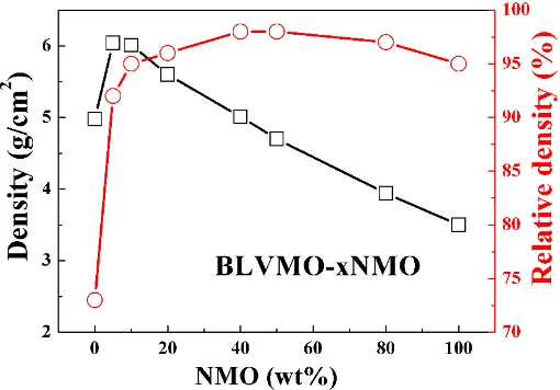
The bulk and relative densities of CSP BLVMO are 4.98 g/cm3and 73%, respectively, which increase
to 6.04 g/cm3and 98% with the addition of NMO (Figure1and Table1). Following an initial increase for x=0.05, bulk densities decreased linearly due to a lower theoretical density of NMO compared with BLVMO (6.85 g/cm3and 3.69 g/cm3for BLVMO and NMO, respectively) [25–28]. The relative densities of (100−x) wt.% BLVMO-x wt.% NMO ceramics are>90% (except pure BLVMO), attaining
98% for 40 wt.% NMO, confirming that dense (100−x) wt.% BLVMO-x wt.% NMO composites could be
Materials2019,12, 1370 3 of 10
Materials 2018, 11, x FOR PEER REVIEW 3 of 10
Figure 1. Bulk and relative densities of (100−x) wt.% (Bi0.95Li0.05)(V0.9Mo0.1)O4 (BLVMO)-x wt.%
Na2Mo2O7 (NMO) ceramic composites.
Table 1. Sintering temperatures (ST), relative densities (ρr), and microwave dielectric properties of BLVMO, NMO and (100−x) wt.% BLVMO-x wt.% NMO ceramics.
Composition ST(°C) ρr(%) εr tanδ(%) Qf (GHz) TCF (ppm/°C)
BLVMO 150 73 30 0.003 1300 +61
5% NMO 150 92 48 0.0014 3565 +41
10% NMO 150 95 48 0.0012 3959 +20
20% NMO 150 96 40 0.0012 4000 +4
40% NMO 150 98 30 0.001 5000 −35
50% NMO 150 98 26 0.001 7000 −46
80% NMO 150 97 16 0.0007 10000 −76
NMO 150 95 12.7 0.0005 12000 −99
BLVMO 690 96 76 0.0006 7000 +81
NMO 610 87 11.6 0.0005 19000 −78
Room-temperature XRD patterns of CSP BLVMO, NMO and (100−x) wt.% BLVMO-x wt.% NMO samples in the 10°–50° 2θ range are shown in Figure 2. BLVMO has a tetragonal scheelite structure (PDF 48-0744) [26−28], with no evidence of splitting of main diffraction peaks. NMO has an orthorhombic structure with symmetry described by the space group Cmca (PDF 01-073-1797, a = 7.164 Å, b = 11.837 Å, c = 14.713 Å, Z = 8) [25]. All reflections in the XRD data for BLVMO-NMO ceramic composites can be ascribed to BLVMO and NMO and the intensity of NMO diffraction peaks increases with the concentration of NMO, as marked in Figure 2. Coexistence of peaks corresponding to BLVMO and NMO appear in all compositions with 0 < x < 1, and there is no apparent shift in peak position, indicating no interaction between these two end-members.
Room-temperature Raman spectra of CSP BLVMO, NMO and (100−x) wt.% BLVMO-x wt.% NMO ceramics are shown in Figure 3. According to group theory and irreducible representations, there are 15 and 129 different vibrational modes in BLVMO and NMO [26−29], respectively, given as follows:
Γ
BLVMO= 3A
g+ 2A
u+ 6B
g+ 4B
u (2)Γ
NMO= 18A
g+ 13A
u+ 15B
1g+ 19B
1u+ 14B
2g+ 18B
2u+ 19B
3g+ 13B
3u (3) [image:4.595.171.426.89.267.2]In BLVMO, nine 3Ag + 6Bg modes are Raman active and six 2Au + 4Bu modes are IR active [26−28]. In NMO, translations of Na and Mo atoms give 3Ag + 2Au + 3B1g + 4B1u + 3B2g + 4B2u + 3B3g + 2B3u and 3Ag + 2Au + 3B1g + 4B1u + 2B2g + 3B2u + 4B3g + 3B3u modes, respectively. Three B1u + B2u + B3u modes are acoustic active and the remaining 12Ag + 9Au + 9B1g + 12B1u + 9B2g + 12B2u + 19B3g + 9B3u modes correspond to stretching and bending modes of MoO4 and MoO6 octahedra [29]. The Raman spectra
Figure 1. Bulk and relative densities of (100−x) wt.% (Bi0.95Li0.05)(V0.9Mo0.1)O4 (BLVMO)-x wt.% Na2Mo2O7(NMO) ceramic composites.
Table 1. Sintering temperatures (ST), relative densities (ρr), and microwave dielectric properties of
BLVMO, NMO and (100−x) wt.% BLVMO-x wt.% NMO ceramics.
Composition ST (◦C) ρ
r(%) εr tanδ(%) Qf(GHz) TCF (ppm/◦C)
BLVMO 150 73 30 0.003 1300 +61
5% NMO 150 92 48 0.0014 3565 +41
10% NMO 150 95 48 0.0012 3959 +20
20% NMO 150 96 40 0.0012 4000 +4
40% NMO 150 98 30 0.001 5000 −35
50% NMO 150 98 26 0.001 7000 −46
80% NMO 150 97 16 0.0007 10000 −76
NMO 150 95 12.7 0.0005 12000 −99
BLVMO 690 96 76 0.0006 7000 +81
NMO 610 87 11.6 0.0005 19000 −78
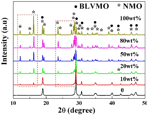
Room-temperature XRD patterns of CSP BLVMO, NMO and (100−x) wt.% BLVMO-x wt.% NMO
samples in the 10◦–50◦2θrange are shown in Figure2. BLVMO has a tetragonal scheelite structure (PDF 48-0744) [26–28], with no evidence of splitting of main diffraction peaks. NMO has an orthorhombic structure with symmetry described by the space groupCmca(PDF 01-073-1797,a=7.164 Å,b=11.837 Å,
c=14.713 Å,Z=8) [25]. All reflections in the XRD data for BLVMO-NMO ceramic composites can be ascribed to BLVMO and NMO and the intensity of NMO diffraction peaks increases with the concentration of NMO, as marked in Figure2. Coexistence of peaks corresponding to BLVMO and NMO appear in all compositions with 0< x<1, and there is no apparent shift in peak position, indicating no interaction between these two end-members.
Room-temperature Raman spectra of CSP BLVMO, NMO and (100−x) wt.% BLVMO-x wt.% NMO
ceramics are shown in Figure3. According to group theory and irreducible representations, there are 15 and 129 different vibrational modes in BLVMO and NMO [26–29], respectively, given as follows:
ΓBLVMO=3Ag+2Au+6Bg+4Bu (2)
ΓNMO=18Ag+13Au+15B1g+19B1u+14B2g+18B2u+19B3g+13B3u (3)
In BLVMO, nine 3Ag+6Bgmodes are Raman active and six 2Au+4Bumodes are IR active [26–28].
In NMO, translations of Na and Mo atoms give 3Ag+2Au+3B1g+4B1u+3B2g+4B2u+3B3g+2B3u
and 3Ag+2Au+3B1g+4B1u+2B2g+3B2u+4B3g+3B3umodes, respectively. Three B1u+B2u+B3u
modes are acoustic active and the remaining 12Ag+9Au+9B1g+12B1u+9B2g+12B2u+19B3g+9B3u
[image:4.595.97.502.338.472.2]Materials2019,12, 1370 4 of 10
spectra of (100−x) wt.% BLVMO-x wt.% NMO composites consist of a superposition of the spectral
features exhibited by each individual phase, further confirming the coexistence of BLVMO and NMO in composite ceramics. Furthermore, the intensity of the NMO Raman modes increases with increasing NMO concentration. Several Raman bands in NMO (~86, 832, 872, 920 and 937 cm−1) are visible in all (100−x) wt.% BLVMO-x wt.% NMO compositions, confirming the coexistence of BLVMO and NMO in
the composites.
Materials 2018, 11, x FOR PEER REVIEW 4 of 10
of (100−x) wt.% BLVMO-x wt.% NMO composites consist of a superposition of the spectral features exhibited by each individual phase, further confirming the coexistence of BLVMO and NMO in composite ceramics. Furthermore, the intensity of the NMO Raman modes increases with increasing NMO concentration. Several Raman bands in NMO (~86, 832, 872, 920 and 937 cm−1) are visible in all (100−x) wt.% BLVMO-x wt.% NMO compositions, confirming the coexistence of BLVMO and NMO in the composites.
Figure 2. X-ray diffraction (XRD) patterns of (100−x) wt.% BLVMO-x wt.% NMO ceramic composites.
Figure 3. Raman spectra of (100−x) wt.% BLVMO-x wt.% NMO ceramic composites.
[image:5.595.173.420.182.375.2]Back-Scattered Electron (BSE) scanning electron microscope images of fracture surfaces of conventionally-sintered BLVMO, cold-sintered BLVMO-20wt.%NMO and NMO are revealed in Figure 4. Dense microstructures are visible in all three compositions, in agreement with the data presented in Figure 1 and Table 1. The average grain size of BLVMO (1–2 μm, Figure 4a) is smaller than that of NMO (2–5 μm, Figure 4b), consistent with previous reports [25−28]. Figure 4c,d shows the composites to be composed two chemically distinct and discrete phases with EDS confirming the dark and light contrast to be NMO and BLVMO, respectively, in agreement with XRD and Raman (Figures 2 and 3).
Figure 2.X-ray diffraction (XRD) patterns of (100−x) wt.% BLVMO-x wt.% NMO ceramic composites.
Materials 2018, 11, x FOR PEER REVIEW 4 of 10
of (100−x) wt.% BLVMO-x wt.% NMO composites consist of a superposition of the spectral features exhibited by each individual phase, further confirming the coexistence of BLVMO and NMO in composite ceramics. Furthermore, the intensity of the NMO Raman modes increases with increasing NMO concentration. Several Raman bands in NMO (~86, 832, 872, 920 and 937 cm−1) are visible in all (100−x) wt.% BLVMO-x wt.% NMO compositions, confirming the coexistence of BLVMO and NMO in the composites.
Figure 2. X-ray diffraction (XRD) patterns of (100−x) wt.% BLVMO-x wt.% NMO ceramic composites.
Figure 3. Raman spectra of (100−x) wt.% BLVMO-x wt.% NMO ceramic composites.
[image:5.595.172.424.418.613.2]Back-Scattered Electron (BSE) scanning electron microscope images of fracture surfaces of conventionally-sintered BLVMO, cold-sintered BLVMO-20wt.%NMO and NMO are revealed in Figure 4. Dense microstructures are visible in all three compositions, in agreement with the data presented in Figure 1 and Table 1. The average grain size of BLVMO (1–2 μm, Figure 4a) is smaller than that of NMO (2–5 μm, Figure 4b), consistent with previous reports [25−28]. Figure 4c,d shows the composites to be composed two chemically distinct and discrete phases with EDS confirming the dark and light contrast to be NMO and BLVMO, respectively, in agreement with XRD and Raman (Figures 2 and 3).
Figure 3.Raman spectra of (100−x) wt.% BLVMO-x wt.% NMO ceramic composites.
Materials2019,12, 1370 5 of 10
[image:6.595.164.430.88.318.2]Materials 2018, 11, x FOR PEER REVIEW 5 of 10
Figure 4. The SEM and BSE images of (a) conventionally-sintered BLVMO, (b) cold-sintered NMO, and (c,d) cold-sintered BLVMO-20 wt.% NMO samples.
The microwave properties of (100−x) wt.% BLVMO-x wt.% NMO as a function x are presented in Figure 5 and also listed in Table I. Low relative density (73%) of CSP BLVMO is observed which gives rise to lower εr (30) and Qf (1300 GHz) than for conventionally-sintered BLVMO, Table 1. εr and TCF values decrease linearly from 48 and +41 ppm/°C, respectively, for BLVMO-5 wt.%NMO to 12.7 and −99 ppm/°C for NMO. Near-zero TCF (−4 ppm/°C) is obtained for BLVMO-20 wt.%NMO. Qf
increases from 1300 GHz for BLVMO to 12,000 GHz for NMO, as shown in Figure 5 and Table 1.
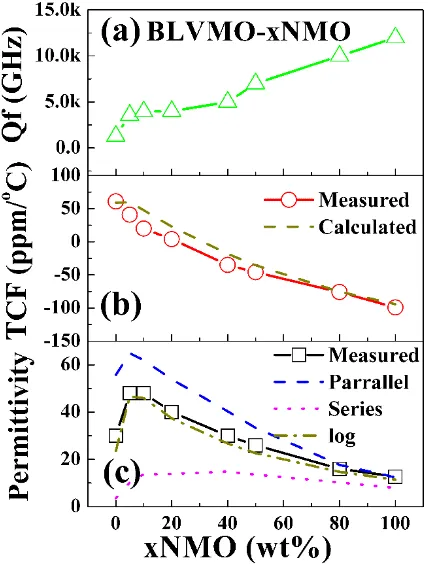
[image:6.595.191.405.457.740.2]Figure 5. The microwave properties of (100−x) wt.% BLVMO-x wt.% NMO ceramic composites as a function of x (NMO fraction). (a) Qf, (b) TCF, (c) εr.
Figure 4. The SEM and BSE images of (a) conventionally-sintered BLVMO, (b) cold-sintered NMO, and (c,d) cold-sintered BLVMO-20 wt.% NMO samples.
The microwave properties of (100−x) wt.% BLVMO-x wt.% NMO as a function x are presented in
Figure5and also listed in Table I. Low relative density (73%) of CSP BLVMO is observed which gives rise to lowerεr(30) andQf (1300 GHz) than for conventionally-sintered BLVMO, Table1.εrand TCF values decrease linearly from 48 and+41 ppm/◦C, respectively, for BLVMO-5 wt.%NMO to 12.7 and
−99 ppm/◦C for NMO. Near-zero TCF (−4 ppm/◦C) is obtained for BLVMO-20 wt.%NMO.Qf increases
from 1300 GHz for BLVMO to 12,000 GHz for NMO, as shown in Figure5and Table1.
Materials 2018, 11, x FOR PEER REVIEW 5 of 10
Figure 4. The SEM and BSE images of (a) conventionally-sintered BLVMO, (b) cold-sintered NMO, and (c,d) cold-sintered BLVMO-20 wt.% NMO samples.
The microwave properties of (100−x) wt.% BLVMO-x wt.% NMO as a function x are presented in Figure 5 and also listed in Table I. Low relative density (73%) of CSP BLVMO is observed which gives rise to lower εr (30) and Qf (1300 GHz) than for conventionally-sintered BLVMO, Table 1. εr and TCF values decrease linearly from 48 and +41 ppm/°C, respectively, for BLVMO-5 wt.%NMO to 12.7 and −99 ppm/°C for NMO. Near-zero TCF (−4 ppm/°C) is obtained for BLVMO-20 wt.%NMO. Qf
increases from 1300 GHz for BLVMO to 12,000 GHz for NMO, as shown in Figure 5 and Table 1.
Figure 5. The microwave properties of (100−x) wt.% BLVMO-x wt.% NMO ceramic composites as a function of x (NMO fraction). (a) Qf, (b) TCF, (c) εr.
Materials2019,12, 1370 6 of 10
Provided there are no chemical reactions between phases, theεrin composites may be predicted by different mixing laws, as follows [22]:
parallel mixing law,ε=V1ε1+V2ε2+V0ε0 (4)
series mixing law, 1/ε=V1/ε1+V2/ε2+V0/ε0 (5)
logarithmic mixing law, ε= εV1
1 ε V2
2 ε V0
0 i.e., lgε = V1lgε1 + V2lgε2 + V0lgε0 (6)
whereε1,ε2andε0are theεrof phase 1, phase 2 and air, respectively andV1,V2andV0(V1+V2+V0
=1) are their respective volume fractions. As shown in Figure5,εrfor (100−x) wt.% BLVMO-x wt.%
NMO composite ceramics is within the range of calculated values for Equations (4) and (5), and close to the values obtained using Equation (6), indicating thatεrfollows a logarithmic mixing law with x. TCF of composites is predicted with a simple mixing rule, which is derived from the Equation (6) [30]:
TCF=V1TCF1+V2TCF2 (7)
where TCF1and TCF2correspond to the TCF of the two phases. TCF is consistent with calculated
values using Equations (7), as shown in Figure5b, suggesting they can be predicted using simple rules of mixture.
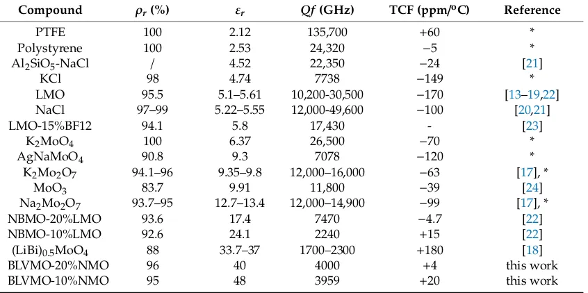
Microwave dielectric properties of various cold-sintered microwave dielectric materials are compared in Table2. Numerous materials (ρr=83.7%–100%) with a range of dielectric properties (2.1 ≤εr≤48, 2240≤Qf ≤135,700 GHz,−174≤TCF≤184 ppm/◦C) can be densified, indicating that CSP is
an effective, and energy-saving strategy for the fabrication of microwave devices [31,32]. (100−x) wt.%
BLVMO-x wt.% NMO (x=10–20) exhibits the highest value ofεr(~48) for near-zero TCFs cold-sintered
[image:7.595.88.511.487.698.2]microwave dielectric materials and is thus attractive for RF applications.
Table 2. Comparison of relative densities, and microwave properties of cold-sintered microwave dielectric materials (* unpublished work,ρr=relative density, PTFE=Polytetrafluoroethylene, LMO=
Li2MoO4, BF12=BaFe12O19, NBMO=Na0.5Bi0.5MoO4, BLVMO=(Bi0.95Li0.05)(V0.9Mo0.1)O4, NMO=
Na2Mo2O7).
Compound ρr(%) εr Qf(GHz) TCF (ppm/oC) Reference
PTFE 100 2.12 135,700 +60 *
Polystyrene 100 2.53 24,320 −5 *
Al2SiO5-NaCl / 4.52 22,350 −24 [21]
KCl 98 4.74 7738 −149 *
LMO 95.5 5.1–5.61 10,200-30,500 −170 [13–19,22]
NaCl 97–99 5.22–5.55 12,000-49,600 −100 [20,21]
LMO-15%BF12 94.1 5.8 17,430 - [23]
K2MoO4 100 6.37 26,500 −70 *
AgNaMoO4 90.8 9.3 7078 −120 *
K2Mo2O7 94.1–96 9.35–9.8 12,000–16,000 −63 [17], *
MoO3 83.7 9.91 11,800 −39 [24]
Na2Mo2O7 93.7–95 12.7–13.4 12,000–14,900 −99 [17], *
NBMO-20%LMO 93.6 17.4 7470 −4.7 [22]
NBMO-10%LMO 92.6 24.1 2240 +15 [22]
(LiBi)0.5MoO4 88 33.7–37 1700–2300 +180 [18]
BLVMO-20%NMO 96 40 4000 +4 this work
BLVMO-10%NMO 95 48 3959 +20 this work
The low sintering temperature and absence of lateral shrinkage suggest that (100−x) wt.%
Materials2019,12, 1370 7 of 10
A GRIN lens is an antenna component for transforming a spherical to a planar wavefront, and enables highly directive antennas and shaped beams. A lightweight, flat lens may be used in the proximity of the feed to realise a compact system that is desired by 5G applications. For practical fabrication, the index profile of a flat lens is usually graded to several tight-fitted rings with radially reducedεr. GRIN lenses may be fabricated from concentric dielectric cylindrical rings with gradedεr,
Figure6a. The simulated electric field of a ceramic GRIN lens is displayed in Figure6b, transforming a spherical to a planar wavefront at 26 GHz.
Materials 2018, 11, x FOR PEER REVIEW 7 of 10
[image:8.595.90.511.195.366.2]A GRIN lens is an antenna component for transforming a spherical to a planar wavefront, and enables highly directive antennas and shaped beams. A lightweight, flat lens may be used in the proximity of the feed to realise a compact system that is desired by 5G applications. For practical fabrication, the index profile of a flat lens is usually graded to several tight-fitted rings with radially reduced εr. GRIN lenses may be fabricated from concentric dielectric cylindrical rings with graded εr, Figure 6a. The simulated electric field of a ceramic GRIN lens is displayed in Figure 6b, transforming a spherical to a planar wavefront at 26 GHz.
ε
r4ε
r3ε
r2ε
r1 R T F Oε
r1 >ε
r2 >ε
r3 > …… >ε
r6ε
r5ε
r6(a) (b)
Figure 6. (a) Lens design principle; (b) Simulated electric field of a ceramic Graded Radial INdex (GRIN) lens that transforming spherical wavefronts into a planar wavefront at 26 GHz.
The design parameters of a lens are shown in Tables 3 and 4. The dielectric lens is comprised of six concentric rings; the outermost has the lowest effective εr (12.7), while the centre has the highest
εr (48). The high εr ceramic reduces the thickness of the lens (miniaturises) compared with low εr
[image:8.595.198.396.489.544.2]materials such as polymers.
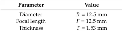
Table 3. Designed parameters of a 3D-printed lens.
[image:8.595.173.423.575.665.2]Parameter Value Diameter R = 12.5 mm Focal length F = 12.5 mm Thickness T = 1.53 mm
Table 4. Dielectric constant values of the concentric dielectric rings.
Ring No. εr Ring Outer Radius(mm)
1 48 1.1
2 40 4.9
3 30 7.8
4 26 8.8
5 16 11.5
6 12.7 12.5
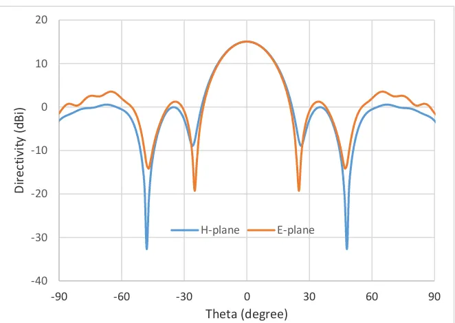
Lens performance was simulated using CST Microwave Studio. An open-ended Ka-band waveguide (7.112 mm × 3.556 mm) was used to illuminate the lens. The boresight directivity is increased across the whole frequency range from 26 to 40 GHz. The relative increase compared to the case with no lens is between 4.6 and 8.5 dB. The aperture efficiency of the lens is ~70% at 26 GHz. The simulated E-plane (i.e., the plane containing the electric field vector) and H-plane (the plane containing the magnetic field vector, normal to the E-plane) radiation patterns of the lens are illustrated in Figure 7.
Figure 6. (a) Lens design principle; (b) Simulated electric field of a ceramic Graded Radial INdex (GRIN) lens that transforming spherical wavefronts into a planar wavefront at 26 GHz.
The design parameters of a lens are shown in Tables3and4. The dielectric lens is comprised of six concentric rings; the outermost has the lowest effectiveεr(12.7), while the centre has the highest εr (48). The highεr ceramic reduces the thickness of the lens (miniaturises) compared with lowεr
materials such as polymers.
Table 3.Designed parameters of a 3D-printed lens.
Parameter Value
Diameter R=12.5 mm
Focal length F=12.5 mm
Thickness T=1.53 mm
Table 4.Dielectric constant values of the concentric dielectric rings.
Ring No. εr Ring Outer Radius(mm)
1 48 1.1
2 40 4.9
3 30 7.8
4 26 8.8
5 16 11.5
6 12.7 12.5
Lens performance was simulated using CST Microwave Studio. An open-ended Ka-band
waveguide (7.112 mm× 3.556 mm) was used to illuminate the lens. The boresight directivity is
Materials2019,12, 1370 8 of 10
Materials 2018, 11, x FOR PEER REVIEW 8 of 10
Figure 7. Simulated far-field radiation patterns of the ceramic GRIN lens at 26 GHz.
4. Conclusions
The (100−x) wt.% BLVMO-x wt.% NMO ceramics with relative density of 92%–98% were fabricated by cold sintering process at 150 °C/30 min/200 MPa. No evidence of chemical interaction was observed in composites, except BLVMOand NMO phases, by means of SEM, XRD and Raman spectroscopy. As x increased, TCF and εr decreased, while Qf increased. Near-zero TCF ~ +4 ppm/°C was measured for BLVMO-20wt%NMO with εr ~ 40 and Qf ~ 4000 GHz. A dielectric GRIN lens was
designed and simulated exhibiting 70% aperture efficiency at 26 GHz, which we propose may be fabricated using (100−x) wt.% BLVMO-x wt.% NMO composites.
Author Contributions: Experiments and writing-original draft preparation, D.W.; Lens design and simulation, S.Z., Y.V., D.C. and W.W.; Supervision, I.M.R.; Data discussion, D.Z., K.S. and A.F.; Writing-review and editing, I.M.R and A.F.
Funding: We acknowledge the EPSRC grants, EP/N010493/1 and EP/L017563/1, “Synthesizing 3D Metamaterials for RF, Microwave and THz Applications” and “Sustainability and Substitution of Functional Materials and Devices” supporting this work.
Conflicts of Interest: The authors declare no conflict of interest.
References
1. Reaney, I.M.; Iddles D. Microwave dielectric ceramics for resonators and filters in mobile phone networks. J. Am. Ceram. Soc.2006, 89, 2063–2072.
2. Sebastian, M.T.; Wang H.; Jantunen H. Low temperature co-fired ceramics with ultra-low sintering temperature: A review. Curr. Opi. Solid State Mater. Sci.2016, 20, 151–170.
3. Zhou, D.; Pang, L.; Wang, D; Reaney, I.M. BiVO4 based high k microwave dielectric materials: a review. J.
Mater. Chem. C2018, 6, 9290–9313.
4. Zhou, D.; Pang, L.; Wang, D; Qi, Z.; Reaney, I.M. High quality factor, ultralow sintering temperature Li6B4O9 microwave dielectric ceramics with ultralow density for antenna substrates, ACS Sustainable Chem.
Eng.2018, 6, 11138–11143.
5. Pang, L.; Zhou, D.; Wang, D.; Zhao, J.; Liu, W.; Yue, Z.; Reaney, I.M. Temperature stable K0.5(Nd1−xBix)0.5MoO4 microwave dielectrics ceramics with ultra-low sintering temperature. J. Am. Ceram.
Soc.2018, 101, 1806–1810. -40 -30 -20 -10 0 10 20
-90 -60 -30 0 30 60 90
Directivity
(dBi)
[image:9.595.133.464.86.321.2]Theta (degree) H-plane E-plane
Figure 7.Simulated far-field radiation patterns of the ceramic GRIN lens at 26 GHz.
4. Conclusions
The (100−x) wt.% BLVMO-x wt.% NMO ceramics with relative density of 92%–98% were fabricated
by cold sintering process at 150◦C/30 min/200 MPa. No evidence of chemical interaction was observed in composites, except BLVMO and NMO phases, by means of SEM, XRD and Raman spectroscopy. As x increased, TCF andεrdecreased, whileQf increased. Near-zero TCF ~+4 ppm/◦C was measured for BLVMO-20wt%NMO withεr~ 40 andQf~ 4000 GHz. A dielectric GRIN lens was designed and
simulated exhibiting 70% aperture efficiency at 26 GHz, which we propose may be fabricated using (100−x) wt.% BLVMO-x wt.% NMO composites.
Author Contributions:Experiments and writing-original draft preparation, D.W.; Lens design and simulation, S.Z., Y.V., D.C. and W.W.; Supervision, I.M.R.; Data discussion, D.Z., K.S. and A.F.; Writing-review and editing, I.M.R and A.F.
Funding:We acknowledge the EPSRC grants, EP/N010493/1 and EP/L017563/1, “Synthesizing 3D Metamaterials for RF, Microwave and THz Applications” and “Sustainability and Substitution of Functional Materials and Devices” supporting this work.
Conflicts of Interest:The authors declare no conflict of interest.
References
1. Reaney, I.M.; Iddles, D. Microwave dielectric ceramics for resonators and filters in mobile phone networks.
J. Am. Ceram. Soc.2006,89, 2063–2072. [CrossRef]
2. Sebastian, M.T.; Wang, H.; Jantunen, H. Low temperature co-fired ceramics with ultra-low sintering temperature: A review.Curr. Opi. Solid State Mater. Sci.2016,20, 151–170. [CrossRef]
3. Zhou, D.; Pang, L.; Wang, D.; Reaney, I.M. BiVO4based high k microwave dielectric materials: A review.
J. Mater. Chem. C2018,6, 9290–9313. [CrossRef]
4. Zhou, D.; Pang, L.; Wang, D.; Qi, Z.; Reaney, I.M. High quality factor, ultralow sintering temperature Li6B4O9
microwave dielectric ceramics with ultralow density for antenna substrates. ACS Sustainable Chem. Eng.
2018,6, 11138–11143. [CrossRef]
5. Pang, L.; Zhou, D.; Wang, D.; Zhao, J.; Liu, W.; Yue, Z.; Reaney, I.M. Temperature stable K0.5(Nd1−xBix)0.5MoO4
microwave dielectrics ceramics with ultra-low sintering temperature.J. Am. Ceram. Soc.2018,101, 1806–1810.
Materials2019,12, 1370 9 of 10
6. Zhou, D.; Pang, L.; Wang, D.; Guo, H.; Yang, F.; Qi, Z.; Li, C.; Jin, B.; Reaney, I.M. Crystal structure, impedance and broadband dielectric spectra of ordered scheelite-structured Bi(Sc1/3Mo2/3)O4ceramic.J. Euro. Ceram. Soc. 2018,38, 1556–1561. [CrossRef]
7. Pang, L.X.; Zhou, D.; Qi, Z.M.; Liu, W.G.; Yue, Z.X.; Reaney, I.M. Structure–property relationships of low sintering temperature scheelite-structured (1−x)BiVO4–xLaNbO4microwave dielectric ceramics.J. Mater.
Chem. C2017,5, 2695–2701. [CrossRef]
8. Zhou, D.; Guo, D.; Li, W.B.; Pang, L.X.; Yao, X.; Wang, D.W.; Reaney, I.M. Novel temperature stable high-εr microwave dielectrics in the Bi2O3−TiO2−V2O5system.J. Mater. Chem. C2016,4, 5357–5362. [CrossRef]
9. Zhou, D.; Li, W.B.; Xi, H.H.; Pang, L.X.; Pang, G.S. Phase composition, crystal structure, infrared reflectivity and microwave dielectric properties of temperature stable composite ceramics (scheelite and zircon-type) in BiVO4-YVO4system.J. Mater. Chem. C2015,3, 2582–2588. [CrossRef]
10. Zhou, D.; Li, J.; Pang, L.X.; Chen, G.H.; Qi, Z.M.; Wang, D.W.; Reaney, I.M. Crystal structure, infrared spectra, and microwave dielectric properties of temperature-stable Zircon-yype (Y,Bi)VO4solid solution ceramics.
ACS Omega2016,1, 963–970. [CrossRef]
11. Ma, J.L.; Fu, Z.F.; Liu, P.; Zhao, L.P.; Guo, B.C. Ultralow-fired Li2Mg3TiO6-Ca0.8Sr0.2TiO3composite ceramics
with temperature stable at microwave frequency.J. Alloys Comp.2017,709, 299–303. [CrossRef]
12. Chen, G.H.; Gu, F.F.; Pan, M.; Yao, L.Q.; Li, M.; Chen, X.; Yang, Y.; Yang, T.; Yuan, C.L.; Zhou, C.R. Microwave dielectric properties of BiVO4/Li0.5Re0.5WO4(Re=La, Nd) ultra-low firing ceramics.J. Mater.
Sci. Mater. Electron.2015,26, 6511–6517. [CrossRef]
13. Kahari, H.; Teirikangas, M.; Juuti, J.; Jantunen, H. Dielectric properties of lithium molybdate ceramic fabricated at room temperature.J. Am. Ceram. Soc.2014,97, 3378–3379. [CrossRef]
14. Kähäri, H.; Teirikangas, M.; Juuti, J.; Jantunen, H. Room-temperature fabrication of microwave dielectric Li2MoO4–TiO2composite ceramics.Ceram. Inter.2016,42, 11442–11446. [CrossRef]
15. Väätäjä, M.; Kähäri, H.; Juuti, J.; Jantunen, H. Li2MoO4-based composite ceramics fabricated from
temperature-and atmosphere-sensitive MnZn ferrite at room temperature.J. Am. Ceram. Soc.2017,100, 3626–3635. 16. Väätäjä, M.; Kähäri, H.; Ohenoja, K.; Sobocinski, M.; Juuti, J.; Jantunen, H. 3D printed dielectric ceramic
without a sintering stage.Sci. Rep.2018,8, 15955. [CrossRef] [PubMed]
17. Guo, J.; Guo, H.; Baker, A.L.; Lanagan, M.T.; Kupp, E.R.; Messing, G.L.; Randall, C.A. Cold sintering: A paradigm shift for processing and integration of ceramics.Angew. Chem. Int. Ed.2016,55, 11457–11461.
[CrossRef]
18. Guo, J.; Baker, A.L.; Guo, H.; Lanagan, M.T.; Randall, C.A. Cold sintering process: A new era for ceramic packaging and microwave device development.J. Am. Ceram. Soc.2017,100, 669–677. [CrossRef]
19. Guo, J.; Berbano, S.S.; Guo, H.; Baker, A.L.; Lanagan, M.T.; Randall, C.A. Cold sintering process of composites: bridging the processing temperature gap of ceramic and polymer materials. Adv. Funct. Mater.2016,26, 7115–7121. [CrossRef]
20. Hong, W.; Li, L.; Cao, M.; Chen, X.M. Plastic deformation and effects of water in room-temperature cold sintering of NaCl microwave dielectric ceramics.J. Am. Ceram. Soc.2018,101, 4038–4043. [CrossRef] 21. Induja, I.J.; Sebastian, M.T. Microwave dielectric properties of mineral sillimanite obtained by conventional
and cold sintering process.J. Euro. Ceram. Soc.2017,37, 2143–2147. [CrossRef]
22. Wang, D.; Zhou, D.; Zhang, S.; Vardaxoglou, Y.; Whittow, W.G.; Cadman, D.; Reaney, I.M. Cold-sintered temperature stable Na0.5Bi0.5MoO4–Li2MoO4microwave composite ceramics.ACS Sustainable Chem. Eng. 2018,6, 2438–2444. [CrossRef]
23. Faouri, S.S.; Mostaed, A.; Dean, J.S.; Wang, D.; Sinclair, D.C.; Zhang, S.; Whittow, W.G.; Vardaxoglou, Y.; Reaney, I.M. High quality factor cold sintered Li2MoO4–BaFe12O19composites for microwave applications.
Acta Mater.2019,166, 202–207. [CrossRef]
24. Zhou, D.; Pang, L.; Wang, D.; Reaney, I.M. Novel water-assisting low firing MoO3microwave dielectric
ceramics.J. Euro. Ceram. Soc.2019,39, 2374–2378. [CrossRef]
25. Zhang, G.Q.; Wang, H.; Guo, J.; He, L.; Wei, D.D.; Yuan, Q.B. Ultra-low sintering temperature microwave dielectric ceramics based on Na2O-MoO3binary system.J. Am. Ceram. Soc.2015,98, 528–533. [CrossRef]
26. Zhou, D.; Qu, W.G.; Randall, C.A.; Pang, L.X.; Wang, H.; Wu, X.G.; Guo, J.; Zhang, G.Q.; Shui, L.; Wang, Q.P.; Liu, H.C.; Yao, X. Ferroelastic phase transition compositional dependence for solid-solution [(Li0.5Bi0.5)xBi1−x][MoxV1−x]O4scheelite-structured microwave dielectric ceramics. Acta Mater.2011,59,
Materials2019,12, 1370 10 of 10
27. Zhou, D.; Pang, L.X.; Qu, W.G.; Randall, C.A.; Guo, J.; Qi, Z.M.; Shao, T.; Yao, X. Dielectric behavior, band gap, in situ X-ray diffraction, Raman and infrared study on (1−x)BiVO4−x(Li0.5Bi0.5)MoO4solid solution.RSC Adv. 2013,3, 5009–5014. [CrossRef]
28. Zhou, D.; Randall, C.A.; Wang, H.; Pang, L.X.; Yao, X. Ultra-low firing high-k scheelite structures based on [(Li0.5Bi0.5)xBi1–x][MoxV1–x]O4 microwave dielectric ceramics.J. Am. Ceram. Soc.2010,93, 2147–2150.
[CrossRef]
29. Saraiva, G.D.; Paraguassu, W.; Maczka, M.; Freire, P.T.C.; de Sousad, F.F.; Mendes Filho, J. Temperature-dependent Raman scattering studies on Na2Mo2O7 disodium dimolybdate.J. Raman Spectrosc.
2011,42, 1114–1119. [CrossRef]
30. Pang, L.X.; Wang, H.; Zhou, D.; Yao, X. A new temperature stable microwave dielectric with low-firing temperature in Bi2MoO6–TiO2system.J. Alloys Comp.2010,493, 626–629. [CrossRef]
31. Wang, D.; Zhou, D.; Song, K.; Feteira, A.; Randall, C.A.; Reaney, I.M. Cold Sintered C0G Multilayer Ceramic Capacitors.Adv. Electro. Mater.2019. [CrossRef]
32. Ibn-Mohammed, T.; Randall, C.A.; Mustapha, K.B.; Guo, J.; Walker, J.; Berbano, S.; Koh, S.C.L.; Sinclair, D.C.; Reaney, I.M. Decarbonising ceramic manufacturing: A techno-economic analysis of energy efficient sintering technologies in the functional materials sector.J. Euro. Ceram. Soc.2019. submitted.