Microstructure and Tensile Strength of Stainless Steel Wires Micro Spot Melted by YAG Laser
5
0
0
Full text
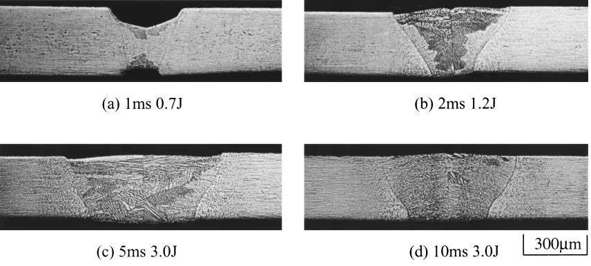
(2) 3084. K. Uenishi et al.. were strained at a cross-head speed of 3.3 × 10⁻³ mm/s. To estimate the corrosion resistance in a quasi biological environment, microstructure and tensile strength of the samples after the immersion in a 0.9%NaCl (JIS T0302) at 318 K for 1800 ks and 3600 ks were compared with those of as spot melted or as received stainless steel wires. Crosswise welding was also performed by using the 0.35 mm diameter wires with the same laser conditions as those for spot melting. Similar to the case of laser spot melting, effect of laser power input on the joint tensile strength was investigated. 3. Results and Discussion 3.1 Spot melting 3.1.1 Effect of laser condition on the spot melting Figure 2 shows the cross sections of spot melted stainless steel wires. Any cracks or porosities were not confirmed, but especially in a shorter pulse duration, the morphology of the sample became irregular probably due to the increased power density of laser. With increasing the power input, the penetration depth and melted area increased, but too much power input caused the break down of the wires after melting. Figure 3 shows the effect of power input on penetration ratio, which is the ratio of penetration depth to the wire diameter, and on the width of spot melted metal. With decreasing the pulse duration and wire diameter, width of melted metal decreased. By using a shorter pulse duration of laser, the sound melting with the weld meld width of less than. Fig. 1 Definition of melted metal width (w) and penetration depth (d) in cross section.. 0.3 mm was achieved for the 0.35 mm diameter wires. On the contrary, the favorable laser condition range where fully penetrated melting without any melting imperfections can be achieved, became smaller for the shorter pulse duration and also for the thinner wires as shown in Fig. 4. It can be concluded that laser spot melting with a shorter pulse duration is effective to minimize the melted area because of the smaller laser power input, but needs more precise control of laser conditions to achieve the stable melting. Similarly, melting of thinner wire needs more precise control of laser conditions. 3.2 Microstructure of spot melted metal Figure 5 shows the representative microstructure of spot melted and heat affected materials by laser. In entire laser conditions, the microstructure of the melted metal was a austenite cellular dendrite structure that grew from fusion boundary to center of the melted metal. δ ferrite, which is contrasted as dark holes, was slightly observed on the boundary of primary precipitated austenite cell8, 9) especially around the center of the melted metal. The cell size changed by the position, and it was about 2.5–3.5 µm near the center and was 0.5–1.5 µm for fusion boundary, which became slightly larger with increasing the power input. Such a fine cell microstructure has been observed for the rapidly quenched stainless steels like laser surface melting. By referring previously estimated the relation between cell size and cooling rate,10) the cooling rate during laser melting was estimated about 2×10⁵ –2×10⁶ K/s around fusion boundary and about 5×10³ – 3 × 10⁴ K/s around center of the melted metal. Stainless steel with a fine grained structure and smaller volume fraction of δ ferrite is reported to rather enhance the corrosion resistance,11, 12) so at least it can be presumed that laser spot melting will not degrade the corrosion resistance of SUS304. The microstructure of heat affected material, shown in Fig. 5(d), was a recrystallized or a fiber structure, since the base material is highly deformed for drawing. This microstructure was also observed by tempering the base metal at 1173 K. For the arc or laser welded stainless steel, sensitization in heat affected zone (HAZ) frequently degrades the corrosion resistance. It has been reported that HAZ after etching by oxalic. Fig. 2 Cross sections of stainless steel wires spot melted by various power input and pulse duration..
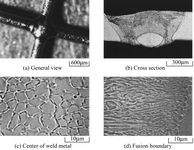
(3) Microstructure and Tensile Strength of Stainless Steel Wires Micro Spot Melted by YAG Laser. 3085. Fig. 3 Effect of power input on (a) penetration ratio and (b) width of the spot melted metal.. Fig. 4 Laser condition range where reasonable melting can be achieved.. acid exhibits a ditch like microstructure when sensitization of HAZ occurs.13) For the samples obtained in this research, HAZ exhibited not a ditch structure but a step-like structure similar to that of the tempered base metal. Consequently, corrosion of HAZ can be considered to be comparable with base materials. 3.3 Properties of spot melted stainless steel Figure 6 shows the effect of laser conditions on the tensile strength of spot melted stainless steel. In any welding conditions, tensile strength slightly increased with decreasing the input energy and reached to a maximum about 660 MPa both for the φ0.25 and φ0.35 wires. Fracture occurred in the melted metal and fracture surface revealed a ductile cup-andcone structure. Compared with the tensile strength of the base metal, which was about 2300 MPa, that of spot melted material was smaller. since base metal is rather strengthened by work hardening. Although the fracture elongation hardly changed between base metals and spot melted wires, the reduction in the area was much larger for spot melted wires than that for base metals. So it can be concluded that melted metal is more ductile than base metal. When base metal is tempered at 1173 K, the tensile strength decreased down to about 600 MPa, which is comparable with that of the spot melted material obtained in this study. Figure 7 shows the changes in the tensile strength of spot melted wires by the immersion in a pseudo biological environment using a NaCl solution. By the immersion for 1000 h, the melted area hardly attacked and tensile strength did not changed. So the laser melted material is presumed to retain favorable corrosion resistance in a biological environment. 3.4 Crosswise welding of stainless steel wires Figure 8 shows the general view and cross section of crosswise welded joints. Welding free from welding imperfections like crack and porosity was achieved. When welding was performed by various laser conditions, weld joints morphologies were classified into 3 types by the melting state of a lower wire. Namely, lower wire is hardly melted, partially melted and fully melted. When input energy was less than 4.0 J, lower wire was hardly melted. Melted area of lower wire increased with increasing input energy. The joint exhibited the maximum tensile fracture load of 80 N which is slightly higer than that for spot melted wires when lower wire was partially melted and fracture occurred in the boundary between weld metal and HAZ. The microstructure of the weld metal was a cellular dendrite structure similar to that of spot melted metal. Cell size.
(4) 3086. K. Uenishi et al.. Fig. 5 Microstructure of spot melted and heat affected SUS304 prepared by the 3.0J of power input and 10 ms of pulse duration.. Fig. 6 Effect of laser conditions on the tensile strength of spot melted stainless steel.. was about 1.0 µm around fusion boundary and about 5.0 µm around center of the weld metal. By referring the relation between cell size and cooling rate, the cooling rate during laser welding was estimated about 4 × 10⁵ K/s around fusion boundary and about 1 × 10³ K/s around center of the weld metal. Although cell size of crosswise welded metal was a little larger than that of spot melted metal, it is considered that this will hardly affect the corrosion resistance. 4. Conclusions SUS304 stainless steel wires were micro spot melted by using YAG laser in order to investigate the applicability of laser micro welding to the fabrication of medical devices. The. Fig. 7 Effect of immersion time in 0.9%NaCl at 328 k on tensile strength of spot melted wires.. results are summarized as follows. (1) Both for the 0.25 mm and 0.35 mm diameter wires, sound spot melted samples free from any defects were prepared. With increasing the power input, the penetration depth and melted area increased, but too much power input caused the break down of the wires after melting. Laser irradiation with a shorter pulse duration is effective to minimize the melted area but needs more precise control of laser conditions to achieve the stable melting. Similarly, melting of thinner wire needs more precise control of laser conditions. Melted metal width decreased with decreasing the input energy and pulse duration. (2) The microstructure of the melted metal was a austenite cellular dendrite structure with a cell size of less than about.
(5) Microstructure and Tensile Strength of Stainless Steel Wires Micro Spot Melted by YAG Laser. Fig. 8. 3087. General view and cross section of crosswise weld joints prepared by the 6.0 J of power input and 10 ms of pulse duration.. 5 µm. δ ferrite was slightly observed on the boundary of primary precipitated austenite cell especially in the center of the melted metal. This microstructure was developed by the rapid solidification of melted materials at a approximate order of 104 K s−1 . The microstructure of HAZ was a recrystallized microstructure. Any sensitizations in HAZ were not recognized. (3) Tensile strength of the spot melted wires was 660 MPa, which is almost the same as that of tempered base materials. (4) By the immersion in a quasi biological environment, microstructure and tensile strength of the spot melted wires hardly changed from those for as melted wires. Coupled with the results of the microstructural observation for the spot melted and heat affected material, corrosion resistance of the melted samples is estimated to be comparable with that of base material. (5) Crosswise joints were also successfully prepared by laser spot welding of wires. The maximum tensile fracture load reached to 80 N, suggesting the laser micro welding is applicable to the fabrication of biomedical devices. Acknowledgements The authors thank the staffs in Laserx Co. Ltd., for the ex-. perimental help about laser irradiation. This research is financially supported by JSPS grant-in aid for Scientific Research. REFERENCES 1) H. Hamanaka: Materia Japan 37 (1998) 834–841 (Japanese). 2) T. Yoneyama and I. Kobayashi: Nondesructive inspection 49 (2000) 420–423 (Japanese). 3) W. S. Chang and S. J. Na: J. Mater. Proc. Tech. 120 (2002) 208–214. 4) K. Uenishi, M. Seki, M. Takatsugu, K. F. Kobayashi, T. Ikeda and A. Tsuboi: Proc. Inter. Cong. on Laser Advanced Materials Processings, (2002) Osaka Japan, in press. 5) K. Nishimoto: J. Jpn. Weld. Soc. 66 (1997) 24–41 (Japanese). 6) Y. Araki and F. Matsuda: J. High Temper. Soc. 1 (1975) 160–168 (Japanese). 7) M. Seki, H. Yamamoto, M. Nojiri, K. Uenishi and K. F. Kobayashi: J. Japan Inst. Metals. 64 (2000) 632–640 (Japanese). 8) K. Nishimoto, H. Mori and Y. Nakao: ISIJ Int. 35 (1995) 1265–1271. 9) K. Nishimoto, H. Mori and Y. Nakao: IIW Doc. IX-1783-94 (1995) 1–15. 10) W. P. Zhang: Doctoral thesis, Osaka University, September (1989). 11) Y. Nakao, K. Nishimoto and M. Ishizaki: Quart. J. Jpn. Weld Soc. 9 (1991) 97–104. 12) Y. Nakao, K. Nishimoto and W. P. Zhang: Quart. J. Jpn. Weld Soc. 9 (1991) 111–116. 13) H. Kokawa: Materia Japan 35 (1996) 655–662 (Japanese)..
(6)
Figure


Related documents
The aim of the BUMPES trial was to evaluate whether, in nulliparous women with low dose epidural analgesia, being upright during the second stage of labour increased the chance
Base your answer to the following question on the passage below and on your knowledge of social studies. He who, being of weak faculties [abilities], develops the wisdom of the
Cengage Learning reserves the right to remove additional content at any time if subsequent rights restrictions require it... Tucker, Richard, and
TEXAS INSTRUMENTS 25 DISPONIBILE.. CD74ACT
Our review focuses on the basics and clinical application of critical care ultrasound in diagnosing common lung disease, COVID-19 pulmonary lesions, pediatric COVID-19,
Then, the paper will also focus on the study of Yundang lake basin water pollution control measures and practice, expounds the improvement measures and
Sharing working knowledge and industry experience in the areas of auditing financial service clients, such as private equity fund and hedge fund clients. Helping students to
