Diffusion Bonding of TiAl Alloy to Eutectoid Steel
and its Interfacial Self-destruction Behavior
Yasuhiro Morizono
1, Minoru Nishida
2, Akira Chiba
2, Takateru Yamamuro
2,
Yusuke Kanamori
2;*1and Takanobu Terai
2;*21Shock Wave and Condensed Matter Research Center, Kumamoto University, Kumamoto 860-8555, Japan
2Department of Mechanical Engineering and Materials Science, Kumamoto University, Kumamoto 860-8555, Japan
Interfacial microstructures and bonding strength of TiAl alloy/eutectoid steel joints have been investigated from the viewpoint of diffusion barrier effect of carbide layer formed at the interface. Diffusion bonding was performed at 1073 to 1273 K for 3.6 ks in a vacuum, and then several specimens were heated at 1073 to 1273 K for 10.8 to 86.4 ks in evacuated quartz tube to examine the growth behavior of reaction layer. The joint has essentially four kinds of the reaction layers. They are composed of two layers with Ti, Al and Fe elements, TiC layer containing Fe-Al compounds and ferrite layer. This indicates that the joint is difficult to have stable diffusion barrier layer consisting only of the TiC due to contribution of Al element to the interfacial reaction. Although the joint bonded at 1073 K shows high bonding strength of 160 MPa, the strength dramatically decreases with increasing bonding temperature. In addition, self-destruction phenomenon is recognized at the interface in the joints heat-treated at 1173 and 1273 K, and the origin is also discussed.
(Received July 14, 2003; Accepted December 1, 2003)
Keywords: TiAl intermetallic compound, eutectoid steel, diffusion bonding, interfacial reaction, bonding strength, self-destruction
1. Introduction
Titanium aluminide, TiAl, has been expected as a high temperature structural material in the aerospace and auto-mobile industries because of its low density and high strength at elevated temperature. However, its poor ductility at room temperature, low fracture toughness and poor workability hinder the practical use of this material. To overcome these disadvantages, alloy design and microstructural control have been studied extensively with the judicial choice of a processing technique for industrial applications. Among problems for solution, joining is a fundamental and indis-pensable technology to utilize effectively the TiAl. The TiAl has been bonded to itself,1–7) ceramics8) and high melting point metals9) on the assumption of high temperature applications, while steel has been also selected as a combinatorial companion due to its extensive use.10,11)These joining have been achieved by diffusion bonding including the use of metal insert and superplastic deformation,1,3,4,6–9,11) brazing,10)friction welding2)and electron beam welding.5)In each case, control of interfacial reaction, thermal stress and defects such as void and oxide film is important to the sound joint. Especially, it is difficult to suppress the reaction between TiAl and dissimilar material because Ti and Al elements have high reactivity.
The present authors have investigated bonding character-istics and interfacial microstructures of various Ti/steel joints produced by explosive welding and diffusion bond-ing.12–16)One of important aspects in our studies is diffusion barrier behavior of titanium carbide (TiC) layer formed at the interface, which has been also reported by Momonoet al.17) and Fujitaet al.18)The TiC layer acts as a barrier for diffusion
of constituent elements into each parent material, and inhibits the formation of intermetallic compounds such as FeTi and Fe2Ti. Consequently, this enables the Ti/steel joints to maintain high bonding strength even after prolonged heat treatment at elevated temperatures.
In the present study, the TiAl is bonded directly to eutectoid steel, and the interfacial microstructures and bonding strength are investigated. Carbon content in the used steel is 0.82 mass% and is sufficient to produce the TiC layer in the case of the Ti/steel joints.13,16)Thus the TiC layer is expected to be of help to the suppression for interfacial reaction between the TiAl and the steel. In addition, self-destruction phenomenon is characteristically observed in the heat-treated joint. This origin is also discussed as an available phenomenon for establishment of reversible interconnection with bonding and separating operations.19)
2. Experimental Procedure
The materials used were Ti-36 mass% Al alloy, which was located inphase region on Ti-Al binary phase diagram, and commercially served eutectoid steel. The TiAl was produced by arc melting process. The obtained ingot was homogenized at 1273 K for 86.4 ks in a vacuum of less than310 3Pa and then was cut into disk shape of 5 mm in diameter and 0.5 mm in thickness by electric discharge machine. The steel contained 0.82 mass% C, 0.18 mass% Si, 0.40 mass% Mn, 0.013 mass% P, 0.021 mass% S, 0.10 mass% Cr and 0.08 mass% Cu, and corresponded to SK5 tool steel specified by Japanese Industrial Standards Committee. Its dimensions were 5 mm in diameter and 5 mm in height. The bonding surface of the TiAl and the steel was finished with #1200 emery paper. Before bonding treatment, all materials were degreased in acetone using ultrasonic cleaner and were dried with hot air.
The bond couple whose stacking sequence was steel, TiAl disk and steel was fixed in jig composed of two Mo rods and *1Graduate Student, Kumamoto University. Present address: Kyushu
Bureau of Economy, Trade and Industry, Hakata 812-8546, Japan. *2Undergraduate Student, Kumamoto University. Present address: Hitachi
two SUS304 austenitic stainless steel blocks. This assembly was heated at 1073 to 1273 K for 3.6 ks in a vacuum of less than310 3Pa, and the diffusion bonding of the TiAl to the steel was completed. To examine the growth behavior of reaction layer, several specimens were heated at 1073 to 1273 K for 10.8 to 86.4 ks in evacuated quartz tube and then were furnace-cooled to room temperature.
The specimens were cut perpendicular to the interface to reveal the microstructural aspects. The cross sections were ground with emery papers and then were finished with alumina powders. After etching, they were examined by optical microscopy and scanning electron microscopy (SEM) equipped with energy dispersive X-ray spectroscopy (EDX). The specimens for transmission electron microscopic (TEM) observations were prepared from slices of about 0.1 mm in thickness, which were obtained by cutting and grinding of the joint. Disks of 3 mm in diameter containing the bonding interface were made from the slices by ultrasonic cutting tool and were finished with an argon ion beam-milling machine. Accelerating voltage on TEM observations was 200 kV.
Bonding strength of the obtained joints was evaluated at room temperature by shear test, which was performed at a crosshead speed of 8:310 3mm/s using Instron type tensile machine equipped with special gripping device. X-ray diffraction (XRD) was carried out on fracture surface of the joint after the shear test.
3. Results and Discussion
3.1 Interfacial microstructures of TiAl/eutectoid steel joints
Figures 1(a) to (c) show optical micrographs of the interface in the TiAl/eutectoid steel joints bonded at 1073, 1173 and 1273 K for 3.6 ks, respectively. The upper and lower sides in the micrographs are the TiAl and the steel. Bonding of the TiAl to the steel is achieved by the present procedure. Several reaction layers are clearly seen in the each joint. Although there are two and three kinds of the reaction layers in the joints bonded at 1073 and 1173 K for 3.6 ks respectively, their microstructures became like Fig. 1(c) by increase of holding time. Thus the joint has essentially four kinds of the reaction layers marked with I to IV in Fig. 1(c). In Figs. 1(a) and (b), the regions corresponding to layers III
[image:2.595.307.548.176.553.2]and IV in Fig. 1(c) are mainly seen. Since Ti/eutectoid steel interface under the same condition has single layer consisting only of TiC,13,16)these results indicate that Al element in the Ti alloy is responsible for the formation of multiple reaction layers.
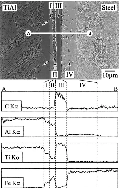
Figure 2 shows the result of SEM-EDX analysis of the interface in the TiAl/eutectoid steel joint bonded at 1273 K
Fig. 1 Optical micrographs of the bonding interface in TiAl/eutectoid steel joints bonded at (a) 1073, (b) 1173 and (c) 1273 K for 3.6 ks. Fig. 2 Result of SEM-EDX analysis of the bonding interface in TiAl/
[image:2.595.84.515.599.769.2]for 3.6 ks. There is an analysis position on white line between A and B. The reaction layers marked with I to IV in the micrograph are equal to those in Fig. 1(c). Ti, Al and Fe elements are detected in the layers I and II. These layers differ in composition ratio. Ti and Al contents in the layer I are higher than those in the layer II, while Fe content lowers in the layer I. It is noteworthy that microcracks indicated by double arrows are introduced irregularly in the layer I. These existences influence bonding characteristics and self-destruc-tion behavior described later. In the layer III, the formaself-destruc-tion of TiC is suggested by enrichment of Ti and C elements. Although the TiC layer formed in the Ti/eutectoid steel joint serves as a diffusion barrier for constituent elements,13) the TiAl/steel joint shows the diffusion of Al and Fe into each parent material across the layer III. Thus the layer III is quite unlikely to consist only of the TiC. On the other hand, main component in the layer IV is Fe element, and a small amount of ferrite-stabilizing Al element diffuses into this layer. This is identified as ferrite layer, which is formed by not only decarbonization associated with enrichment of C in the layer III but also stabilization by the diffusion of Al.
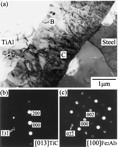
Figure 3(a) shows a bright field image of the bonding interface in the TiAl/eutectoid steel joint bonded at 1073 K for 3.6 ks. The specimens for TEM observations, which were bonded at 1273 K, could not be prepared because of its low bonding strength as mentioned later. The reaction layer consisting of areas B and C in the micrograph is essentially equal to the layer III in Figs. 1 and 2. Electron diffraction patterns taken from the areas B and C are shown in Figs. 3(b) and (c), respectively. These reaction products are found to be
TiC and Fe2Al5 compounds. It was thought that the joints bonded at 1173 and 1273 K also had such a microstructure, since the diffraction peaks of TiC, Fe2Al5 and Fe3Al were detected as a reaction product by XRD after shear test regardless of bonding temperature. However, the Fe3Al has not been confirmed by TEM observations. Meanwhile, there is a reaction product indicated by double arrow in Fig. 3(a). In this region, the diffusion of Fe into the TiAl was detected, but we have not yet led to its detailed identification.
TiAl/steel joint is difficult to have diffusion barrier layer of TiC, even when eutectoid steel with high carbon content is used. Therefore, the use of metal insert is necessary for restraint of marked reaction at the bonding interface.
3.2 Bonding strength of TiAl/eutectoid steel joints
Shear test was carried out to clarify the effect of interfacial reaction on bonding characteristics in TiAl/eutectoid steel joints. Figure 4 shows the relationship between bonding temperature and shear strength of as-bonded specimens. 7-times-test was conducted for each kind of joint, and the average value is plotted in the figure. For comparison, Ti/ eutectoid steel joint, which had diffusion barrier layer of TiC at the interface, was also prepared in the same way. The bonding strength of the TiAl/steel joint bonded at 1073 K is 160 MPa and approximates that of the Ti/steel joint. This value is superior to the lower limit of shear strength for various Ti/steel joints established by Japanese Industrial Standards Committee (JIS G 3603), which is 140 MPa. Thus it can be expected that the TiAl/eutectoid steel joint bonded at 1073 K is located in a practical level. However, the strength decreases with increasing bonding temperature. Fracture position of the joint after the shear test was at the interface in all cases. As mentioned above, the reaction products detected by XRD were TiC, Fe2Al5 and Fe3Al regardless of bonding temperature, and their diffraction peaks became clear with increasing bonding temperature. Thus the degradation of the bonding strength is attributed to the growth of the reaction layer and the introduction of micro-cracks seen in Fig. 2
Ti/steel joint with only TiC layer shows high bonding strength independent of the bonding temperature.
Conse-Fig. 3 (a) Bright field image of the bonding interface in TiAl/eutectoid steel joint bonded at 1073 K for 3.6 ks. (b) and (c) Electron diffraction patterns taken from areas B and C in (a), respectively.
[image:3.595.48.291.445.747.2] [image:3.595.323.529.579.747.2]quently, the control of interfacial reaction between the TiAl and the steel is found to be the most important problem to enhance bonding characteristics.
3.3 Self-destruction behavior between TiAl and steel
To investigate the growth behavior of reaction layer, as-bonded specimen was heat-treated in evacuated quartz tube and then was furnace-cooled to room temperature. However, several specimens were separated between TiAl and steel after heat treatment. This distinctive phenomenon was investigated in detail.
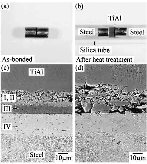
Figures 5(a) and (b) show external views of TiAl/eutectoid steel joints of as-bonded and heat-treated states, respectively. Heat treatment for the specimen shown in Fig. 5(b) was carried out at 1273 K for 10.8 ks after bonding at 1273 K for 3.6 ks. Although the as-bonded specimen has sandwich structure consisting of one TiAl disk and two steel columns, it is broken at the interface by the heat treatment. The situation keeping contact between the TiAl and the steel is also observed in Fig. 5(b). Such a situation had a great deal of cracks and was easily split at the interface, as seen in Figs. 5(c) and (d) showing interfacial microstructures after prolonged heat treatment at 1173 and 1273 K. The reaction layers marked with I to IV in Fig. 5(c) are consistent with those in Figs. 1 and 2. These results indicate that the interfacial destruction occurs predominantly at the layers I and II, which differ in composition ratio of Ti, Al and Fe elements. Actually, the microcracks responsible for the destruction phenomenon are clearly seen in Fig. 2. In many cases, the microcracks existed irregularly in the layer I and were introduced approximately parallel to the growth
direction of this layer. These also increased with increasing temperature and holding time. Thus it is thought that the generation of the microcracks is related to the formation and growth of the reaction layer rather than the influence of thermal stress occurring during the bonding and heat treat-ments.
The growth behavior of the layers I and II in the joints is shown in Fig. 6. Total thickness of the layers I and II is denoted as a vertical axis because of their difficult distinction in the case of brief treatments at 1073 and 1173 K, while holding time in horizontal axis represents square root of total time of the bonding and heat treatments. In the case of 1073 and 1173 K, the linear curves reflecting diffusion controlled growth do not go back to original point. This means that the layers I and II show remarkable growth during the initial bonding treatment. At 1273 K, it is difficult to measure the thickness of the reaction layer, since most joints are separated at the interface. Among the specimens shown in Fig. 6, no microcrack was confirmed only in the joint bonded at 1073 K for 3.6 ks. Furthermore, the disassembly of the joint usually required the total holding time above 57.6 ks at 1173 K and above 14.4 ks at 1273 K within the present experiments. These conditions correspond to the layers I and II of about 7mmin thickness. This critical thickness gives an indication of the disassembly for the TiAl/eutectoid steel joint.
The generation of the microcracks has relation with the formation and growth of the reaction layer consisting of Ti, Al and Fe elements. However, it seems that their propagation into the TiAl parent material and other reaction layers requires contributing factors such as thermal stress. Thermal expansion coefficient of eutectoid steel is 14:710 6K 1 (273973K),20)and that of Ti-47.8 at%Al alloy has been reported to be about 14:010 6K 1 (300900K).21) Although these values approach to each other and detailed properties of the reaction layers in the joint is unclear now, the development of the microcracks may be affected by the thermal stress due to the difference of physical properties such as thermal expansion coefficient. On the other hand, as shown in Fig. 2, phase transformation between the eutectoid steel and ferrite layer also has a possibility of contribution to Fig. 5 (a) and (b) External views of TiAl/eutectoid steel joints of
as-bonded and heat-treated states, respectively. Heat treatment was carried out at 1273 K for 10.8 ks after bonding at 1273 K for 3.6 ks. (c) and (d) SEM micrographs of the interface after prolonged heat treatment at 1173 and 1273 K.
[image:4.595.47.290.459.730.2]the destruction phenomenon. The ferrite layer is produced by decarbonization and diffusion of Al element. This grew in proportion to square root of holding time, and activation energy for its growth was estimated to be 90 kJ/mol. This value is approximately equal to the activation energy for the diffusion of C into ferrite matrix.22)From this result and Fe-Al binary phase diagram, it is predicted that ferrite/austenite interface migrates continuously at holding temperatures because of the diffusion of ferrite-stabilizing Al element. Thus the effect of ferrite/austenite transformation with volume change is also considerable for the destruction phenomenon.
TiAl/eutectoid steel joint bonded at 1073 K for 3.6 ks shows high bonding strength as described in previous section. If this joint is heated at 1273 K for a few hours, its disassembly is accomplished by the destruction phenomenon. Consequently, the TiAl/eutectoid steel joint can be regarded as a reversible combination with bonding and separating operations.
4. Conclusions
Interfacial microstructures and bonding strength of TiAl alloy/eutectoid steel joints have been investigated from the viewpoint of diffusion barrier effect of carbide layer formed at the interface. In addition, self-destruction phenomenon is found in the heat-treated joint, and the origin is also discussed. The main conclusions are summarized as follows. (1) TiAl/eutectoid steel joint has essentially four kinds of reaction layers. They are composed of two layers with Ti, Al and Fe elements, TiC layers containing Fe-Al compounds and ferrite layer. This indicates that the joint is difficult to have stable diffusion barrier layer consisting only of the TiC due to contribution of Al element to the interfacial reaction. (2) The joint bonded at 1073 K for 3.6 ks has the highest bonding strength of 160 MPa and is expected to be located in a practical level. However, the strength dramatically de-creases with increasing bonding temperature. This degrada-tion is attributed to the growth of reacdegrada-tion layer and the introduction of microcracks at the interface.
(3) The joint can be separated between TiAl and steel after prolonged heat treatment at 1173 and 1273 K. This character-istic behavior is induced by microcracks in the reaction layer consisting of Ti, Al and Fe elements. Consequently, self-destruction phenomenon in the TiAl/eutectoid steel joint is available for establishment of reversible interconnection with bonding and separating operations.
Acknowledgements
The authors would like to express their appreciation to Dr. S. Ii and Mr. H. Koga for their kind assistance in the conduct of the experiments. The present study was supported by the Ministry of Education, Culture, Sports, Science and Tech-nology through a Grant-in-Aid for Encouragement of Young Scientists No. 14750590 (2002–2003) and the support is greatly appreciated.
REFERENCES
1) Y. Nakao, K. Shinozaki and M. Hamada: Q. J. Jpn. Weld. Soc.11 (1993) 538–544.
2) T. Miyashita and H. Hino: J. Japan Inst. Metals58(1994) 215–220. 3) K. Uenishi, H. Sumi and K. F. Kobayashi: Z. Metallkd.86(1995) 270–
274.
4) G. C¸ am, K.-H. Bohm, J. Mu¨llauer and M. Koc¸ak: JOM48, 11 (1996) 66–68.
5) M. C. Chaturvedi, Q. Xu and N. L. Richards: J. Mater. Process. Technol.118(2001) 74–78.
6) N. Masahashi, S. Hanada and Y. Mizuhara: Mater. Trans.42(2001) 1028–1034.
7) Y. Morizono, R. Kumagae, M. Nishida, Y. Mizuta and A. Chiba: Mater. Trans.44(2003) 754–758.
8) H. J. Liu, J. C. Feng and Y. Y. Qian: Scr. Mater.43(2000) 49–53. 9) F.-Y. Hsu, G.-X. Wang, H.-J. Klaar and F. Pirwitz: Metall. Mater.
Trans. A27A(1996) 2285–2292.
10) T. Noda, T. Shimizu, M. Okabe and T. Iikubo: Mater. Sci. Eng.A239– 240(1997) 613–618.
11) S. Seto, K. Matsumoto, T. Masuyama, M. Hiroshima and H. Ishikawa: Q. J. Jpn. Weld. Soc.16(1998) 59–65.
12) M. Nishida, A. Chiba, Y. Honda, J. Hirazumi and K. Horikiri: ISIJ Int. 35(1995) 217–219.
13) A. Chiba, M. Nishida, Y. Morizono and K. Imamura: J. Phase Equilibria16(1995) 411–415.
14) A. Chiba, M. Nishida, Y. Morizono and K. Imamura: Tetsu-to-Hagane 83(1997) 736–741.
15) Y. Morizono, M. Nishida, A. Chiba and K. Imamura: Tetsu-to-Hagane 85(1999) 340–345.
16) Y. Morizono, M. Nishida and A. Chiba: ISIJ Int.42(2002) 645–650. 17) T. Momono, T. Enjo and K. Ikeuchi: Tetsu-to-Hagane73(1987) 1590–
1597.
18) D. Fujita and K. Yoshihara: Tetsu-to-Hagane79(1993) 1088–1094. 19) N. Hosoda, L. Yang, Y. Kyogoku and T. Suga: J. Jpn. Inst. for
Interconnecting and Packaging Electronic Circuits11(1996) 510–513. 20) Metals Data Book, ed. by Japan Inst. Metals (Maruzen Co., Ltd. 1993)
122.
21) A. Sugawara and I. Takahashi: Jpn. J. of Thermophysical Properties 5 (1991) 184–189.