Microstructure of Plasma-Sprayed Cast Iron Splats with Different Particle Sizes
Magdi F. Morks
1, Yoshiki Tsunekawa
1, Masahiro Okumiya
1and Madiha A. Shoeib
2 1Toyota Technological Institute, Nagoya 468-8511, Japan2Central Metallurgical Research and Development Institute, Cairo, Egypt
The superior wear-resistant property of cast irons is closely linked with their microstructure, in which graphite formation in plasma-sprayed cast iron coatings causes distinct characteristics owing to its self-lubricating property. Since the solidification rate generally affects graphite formation, the optimum in spray parameters such as substrate temperature, ambient pressure, particle size and spray distance is required to slow down the solidification rate, as well as to improve the adhesive strength of splats. In this study, cast iron splats were induced on an aluminum alloy substrate by plasma spraying using alloyed cast iron powder high in silicon and aluminum in a low pressure argon atmosphere. Then, the effects of particle size on the microstructure and adhesive strength of splats were investigated by introducing the correlation between the solidification rate and the microstructure. Spraying with large particles leads to an increase in the number fraction of disk splats and a slight decrease in their adhesive strength. Cross-sectional observations reveal fine graphite growing in splats nearly perpendicular to the substrate surface.
(Received October 30, 2002; Accepted January 14, 2003)
Keywords: cast iron, plasma spraying, particle size, microstructure, graphite, splat morphology, adhesion
1. Introduction
Recently, much attention has been given to aluminum alloys as outstanding base materials in many industrial applications such as automotive cylinder blocks because of their low density and high thermal conductivity. In spite of their advantageous properties, aluminum alloys exhibit poor wear resistance owing to their softness, so that surface modification is required especially for high-load bearing sliding components. A variety of processes have been successfully applied to improve the anti-wear property of cast aluminum alloy cylinder blocks: selectively incorporated metal matrix composites,1) composite electroplating2) and thermal spraying of steel.3,4)
In addition to sprayed steel coatings, sprayed coatings of cast iron with superior wear resistance are clearly expected to modify aluminum alloy surfaces. The performance of cast iron coatings depends on the behavior of individual droplets flattened and solidified upon impact against a substrate. Spray parameters such as substrate temperature, ambient pressure, particle size and spray distance have a direct influence on the solidification rate of splats and thus on their coating proper-ties. Although graphitization in plasma-sprayed cast iron coatings has not quite been perfected because of the high solidification rate of splats, among the promising methods to promote graphite formation is to optimize spray parameters to slow down the solidification rate, as well as to modify the chemical composition of cast iron powders. Although alloying elements of aluminum and silicon are known as strong graphitizers, aluminum is not commonly applied to conventional cast iron products because aluminum yields poor fluidity of molten cast iron.
The preheat substrate temperature was found to have a great influence on the morphology,5) microstructure and adhesive strength of cast iron splats.6) On the other hand, spraying at low ambient pressure shortens the solidification time due to the thinning of splats,7) that is, enlarging the flattening ratio without pore formation at the interface. Spraying in an argon atmosphere also improves the adhesive
strength and controls heavy in-process oxidation. Besides these two parameters, it is necessary to examine the influence of others on the splat features to achieve the optimum conditions for cast iron coatings containing graphite along with good adhesion.
Particle size is expected to have a direct influence on the features of cast iron splats as well as on in-process oxidation. This size parameter affects the droplet temperature and velocity just before impinging that, in turn, exerts a major influence on the coating performance through the flattening ratio, the formation of pores, and a reaction layer at the interface.3,8,9) According to Shi and Dear,10) the radial spreading velocity of a droplet impacting a solid surface is approximately three times higher than the impact velocity, while the high impact velocity improves the adhesive strength of splats.
This paper presents the effect of particle size on the behavior of cast iron droplets sprayed on an aluminum alloy substrate with a smooth surface as a fundamental aspect of anti-wear cast iron coatings. With a preheated substrate and controlled atmosphere, this study focuses on the influences of particle size on splat morphology as well as on the microstructure containing graphite and on the adhesive strength depending upon pore and oxide formation at the interface.
2. Experimental Procedure
A gas atomized cast iron powder with a chemical composition of Fe–3.56C–3.32Si–4.08Al (all compositions in mass%) was used as a spray material. After sieving into different particle sizes (dP) in the ranges of 32–38, 38–45,
45–53, 53–63 and 63–75mm, the powder with a differentdP
range was fed into the plasma flame under the spray parameters listed in Table1. Cast iron powder with a different dP range was sprayed at a constant spray distance
of 300 mm and collected on a mirror-finished Al–Si–Cu alloy (ADC12) substrate. The preheat substrate temperature (TS)
was then kept constant at 473 K before spraying and was
continuously monitored by a thermocouple inserted into the substrate center. All sprayings were carried out in an argon atmosphere in such a way that the chamber was evacuated to 1.9 kPa prior to allowing primary argon to pass through up to the operating pressure of 46 kPa.
The number fraction of each of three splat morphologies sprayed with a differentdPrange was calculated by counting
the corresponding splats using an optical microscope. A conductive adhesive tape was used to remove splats from the substrate surface for an examination of pore formation on the bottom-sides of splats.6) The number fraction of removed splats was simultaneously counted to reach an approximate evaluation of their adhesive property.
To examine the splat microstructure and its interface, splat cross-sections were carefully prepared, polished with emery paper, and then buff-polished with a diluted aqueous Al2O3
powder slurry. After cleaning with distilled water and C2H5OH, the cross-sections were etched by a mixed reagent
of nital and small amounts of HF and H2O2 for 10–60 s. A
topside of cast iron splats was prepared by the same procedure as the above to clarify the microstructure, especially focusing on graphite and Fe3C phases. Topside
and bottom-side views of splats were examined by scanning electron microscopy (SEM). Various phases of splats and coatings were identified by X-ray diffractometry (XRD) with Co–K radiation. Element analyses on splat cross-sections were also carried out by electron probe microanalysis (EPMA).
3. Results and Discussion
3.1 Splat morphology with different particle sizes
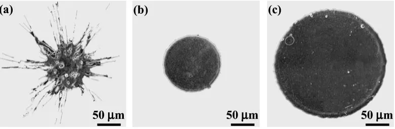
Disk and star-shape are the major morphologies of splats sprayed with different particle sizes (dP) as shown in Fig. 1.
No splashed splats appear under the present spray conditions. Splat appearances are remarkably influenced by dP as
described in the morphology classification curves of Fig. 2. The number fraction of disk splats increases withdPwhereas
that of star-shaped splats decreases. Most splats sprayed with a largedPrange of 63–75mmare a disk shape.
AsdPincreases, its impact velocity decreases as measured
by the present authors11)and Sodeokaet al.12)Small particles have higher impact velocity than that of large particles, and thus the collision force per unit volume becomes higher when
dP decreases. Looking at star-shaped splats, they have a
central disk attached by a number of streaks with length longer than the central disk diameter. The maximum collision force is generated at the tip of the impinging droplet,13) so that the collision force is concentrated at the splat center during flattening. A rapid molten metal flow arises from the central disk periphery and then streaks are formed. Since the impact velocity decreases in the case of a largedP, the force
on the flattening droplets decreases, and the droplets expand homogeneously without disturbance at the central disk periphery, thus forming a regular disk shape. According to this consideration, there should be a critical value for the impact velocity above which star-shaped splats appear and below which disk splats appear. The value of the impact velocity can be determined using a measurement system presented elsewhere.12,14) Disk splats are preferable for coating formation because the layering of disk splats is accompanied by smaller and fewer pores than those of splashed splats. The latter splat morphology reduces the coating performance,15)although there are no splashed splats in the present study because of our use of a preheated substrate.
The flattening ratio (D=d) of disk splats sprayed with a differentdPwas calculated by dividing the splat diameter (D)
by the droplet diameter (d). There is a slight increase in the flattening ratio curve from 3.6 to 3.8 with an increasing averagedP from 35 to 69mm. The slight increase inD=d is
[image:2.595.46.291.92.246.2]explained by the mass reduction due to vaporization during the droplet flight, since small droplets approach slightly higher temperatures at low chamber pressure.12)Taking into
Table 1 Spray parameters for the splat collection on aluminum alloy substrate.
primary plasma gas Ar:3:92104(m3/s)
secondary plasma gas H2:3:92105(m3/s)
arc current 500 (A)
arc valtage 38 (V)
powder carrier gas Ar:4:33105(m3/s)
chamber pressure 46 (kPa)
spray distance 300 (mm)
spray material cast iron
particle size 32–75 (mm)
substrate material ADC12
preheat substrate temperature 473 (K)
Fig. 1 SEM micrographs showing a splat morphology of cast iron sprayed with different particle sizes (dP): (a)32<dP<38mm,
[image:2.595.104.493.632.759.2]consideration an error at an individualD=d,dPseems to have
no significant influence on the D=d. These D=d measure-ments are used to calculate the splat thickness at a different
dP, which will be discussed below in the solidification time
evaluation.
3.2 Adhesion of splats with different particle sizes
The first layered splats impinging on a substrate greatly affect the adhesive property of coatings, so that an improve-ment in the adhesive strength of cast iron splats through the adjusting of spray parameters is of the utmost importance. The adhesive strength of splats was approximately evaluated by a peeling away test.6)This test was simply carried out by counting the number of splats removed by an adhesive tape, so that an increase in the number fraction (NP) of removed
splats indicates the poor level of adhesion. AsdPincreases,
theNPincreases as shown in Fig.3, indicating a decrease in
the adhesive strength of splats. However, the NP of 0.18 at
dP¼63{75mm is still not as high as that for low preheat
temperatures of substrates, that is, NP¼0:39 at a preheat
temperature of 373 K.6)As mentioned earlier, splat adhesion is greatly influenced by pores and oxide formation at the interface.
To explain the weakness of splat adhesion sprayed with large particles, the bottom-side views of cast iron splats were examined as shown in Fig.4. Comparing the two photos in
Fig.4, splats sprayed with large particles are seen to have a few more pores on their bottom-sides than those sprayed with small particles, and pore formation at the interface causes a decrease in the adhesive strength between a splat and its substrate. It seems that large molten droplets absorb more atmospheric gases during the flight owing to the low velocity and then they desorb slightly more gases as pores owing to the relatively slow solidification. Adsorbed gases like H2O
vapor on a substrate surface may cause pore formation at the interface as proposed by Sampath et al.16)However, this is not the reason for the above difference in pore formation because the same preheat substrate temperature and atmo-sphere were applied in this study. Only weakly adhering splats, which have relatively many pores on their bottom-sides, were removed from a substrate surface in both dP.
However, it is difficult to remove star-shaped splats, which exhibit higher adhesive strength than disk splats. As discussed above, star-shaped splats originated from the high collision force at the center of splats, which promotes a firm contact between a splat and its substrate.
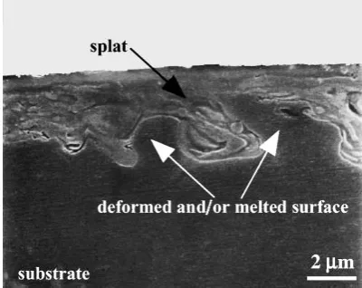
While the droplet is spreading on a substrate, an irregularity develops on the substrate surface due to plastic deformation and also to the partial melting of the surface.6) This creates a kind of mechanical and metallurgical bond, which improves the adhesive property as shown in Fig. 5,
Fig. 3 Change in number fraction of removed splats as a function of particle size (dP).
Fig. 2 Change in splat morphology of cast iron as a function of particle size (dP).
Fig. 4 SEM micrographs showing a bottom-side view of cast iron disk splats sprayed with (a) small (32<dP<38mm) and (b) large
(63<dP<75mm) particles.
Fig. 5 SEM micrograph showing a cross-section view of star-shaped cast iron splat sprayed with small (38<dP<45mm) particles at a short spray
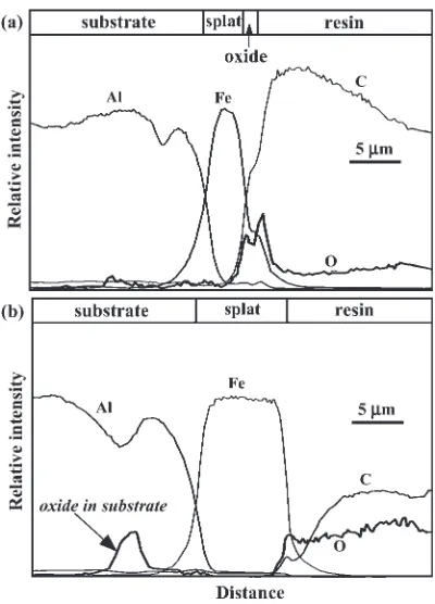
[image:3.595.304.548.72.207.2] [image:3.595.65.275.73.222.2] [image:3.595.326.526.588.747.2] [image:3.595.69.269.618.758.2]although this depicts an extreme case sprayed at a short spray distance of only 100 mm. this kind of irregularity of a substrate surface is a typical feature when molten droplets at a high temperature impinge on a substrate with a low melting point like that of aluminum. Element line analyses of EPMA on the cross-sections of splats sprayed with small and largedP
at a spray distance of 300 mm are shown in Fig. 6. No appreciable oxide layer is observed at the splat/substrate interface because the spraying was done in a low pressure argon atmosphere, indicating that an oxide layer at the interface plays no significant role in splat adhesion under a controlled atmosphere. A thin oxide layer is, however, detected on the splat surface sprayed with small particles owing to their slightly higher temperature. Small droplets are more easily oxidized in plasma flame than large ones, even under the present controlled atmosphere, so that the intersplat adhesion is expected to become lower in the case of a small
dP.
3.3 Estimation of solidification time with different splat thicknesses
Disk splat thickness (x0) can be calculated from the
flattening ratio (D=d) by applying the following equation under the assumption of no evaporation during the droplet flight:
x0¼2ðl=sÞ2=3dP=½3ðD=dÞ2 ð1Þ
wheres andlare the density of solid and liquid particles, respectively. From eq. (1)x0can be estimated at differentdP
by usingD=d values as described in Fig.7.
Assuming the preheat substrate temperature to beTSand
the molten splat temperature Td with no interface thermal
resistance, after partial solidification has occurred in the splat thickness direction (x), the solution of the temperature gradient within the splat is given by eq. (2),17)that is, the heat flux into the splat/substrate interface from the solidifying splat must equal the flux away from the interface from the interface into the substrate:
ðTTiÞ=ðTdTiÞ ¼erf½x=f2ðk0t=0C0PÞ
1=2g ð2Þ
The interface temperature (Ti) is calculated by assuming the
droplet temperature (Td¼2383K) at a spray distance of
300 mm regardless of the particle sizes (dP), although the
droplet temperature actually changes with dP.12) However,
the effect of superheat (T) on the solidification time (tS),
which is defined as an elapsed time to full solidification of a molten splat, must be added to the absorbed latent heat of the molten cast iron. Taking into account the total quantity of heat to be removed from the molten splat and assuming no difference in the density of the liquid and solid cast iron, the effective heat of fusion (H0
f) can be expressed by the sum of
latent heat of fusion (Hf) and the superheat term
(C0
P(liquid)T):
Hf0¼HfþC0P(liquid)T ð3Þ
The calculatedTi is 1570 K in alldP, which reveals that the
substrate surface is partially melted as expected in Fig. 5. Note that the solidification time (tS) is proportional to the
square of the splat thickness (x0). From this information, the
solidification time of the splat can be estimated as described in Fig. 8as a function ofx20 at different dP by applying the
following equation:17)
tS¼x20=ð4 2
Þ 0CP0=k0 ð4Þ
where is a constant, 0 the density of cast iron, C0
P the
specific heat, andk0the thermal conductivity.18)The factor
depends upon the droplet temperature, interfacial tempera-ture, heat capacity of droplet materials, and latent heat of fusion, and can be evaluated by applying the following equation:17)
ðTdTiÞCP0=ð 1=2
HfÞ ¼expð2ÞerfðÞ ð5Þ
As seen in eq. (4), the solidification time increases by increasing the splat thickness and decreasing factor . The lower the droplet temperature the lower the factorand the
Fig. 6 Element distribution on a cross-section of cast iron splats sprayed with (a) small (32<dP<38mm) and (b) large (63<dP<75mm)
particles.
[image:4.595.69.269.69.347.2] [image:4.595.312.542.72.227.2]longer the solidification time. These calculations agree well with the experimental results which showed an increase in graphite intensity withdPdue to a decrease in the
solidifica-tion rate, as will be described below. Thus, simple numerical calculations of solidification time with a differentdPshow an
increase in the splat solidification time with increasingdP.
3.4 Splat microstructure with different particle sizes 3.4.1 Phase identification of cast iron splats
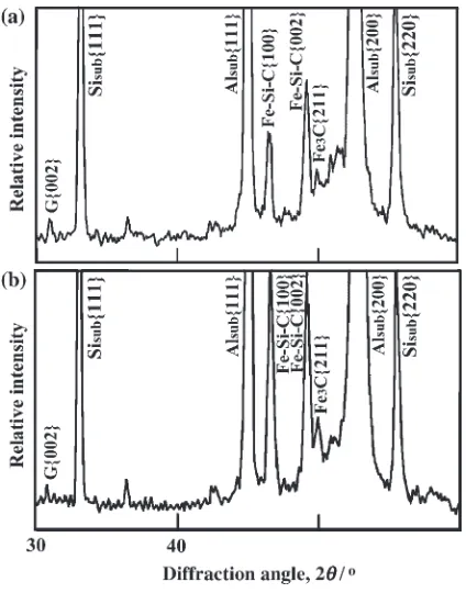
X-ray diffraction patterns of cast iron splats sprayed with small and large particles are shown in Fig.9. The splats are mainly composed of Fe–Si–C, Fe3C and graphite. The
dependence of particle sizes (dP) on the individual phase of
splats cannot be predicted from the corresponding XRD pattern because of the difference in the numbers of splats on an X-ray irradiated area. To overcome this uncertainty, cast iron coatings under the same spray conditions were produced
using small and large particles. The XRD patterns reveal that coatings sprayed with small particles are mainly composed of a rapidly solidified phase of Fe–Si–C and small amounts of graphite. Although cast iron coatings sprayed with large dP
are composed of Fe–Si–C and Fe3C as well as graphite, the
diffracted intensity from graphite increases and that of Fe– Si–C decreases withdP.
The high intensity of the rapidly solidified Fe–Si–C phase, which formed on the coatings sprayed with small dP,
indicates also a high solidification rate. As mentioned above, small particles have higher velocities than large particles. Spraying with small particles increases the possibility of star-shaped splat formations, which are thinner than disk splats and thus solidify faster. On the other hand, large particles form many relatively thick disk splats. Since the solidifica-tion time is proporsolidifica-tional to the square of splat thickness, splats sprayed with large particles solidify slower than those sprayed with small particles. In addition, a few more pore formation at the interface of splats sprayed with large particles additionally slows down the solidification rate because of the increase in interfacial thermal resistance.
3.4.2 Graphite formation
The top surfaces of cast iron splats sprayed with small and large particles were polished, buffed and etched to reveal the microstructures shown in Fig. 10. Fine graphite clearly appears at the central part of disk splats sprayed with both small and large particles. The individual graphite volume increases withdPbecause of a decrease in the solidification
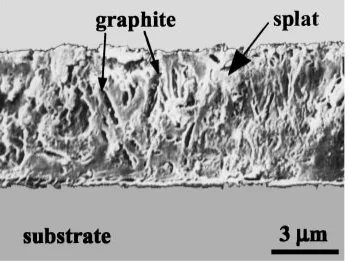
rate. Since measuring the distribution of graphite inside the splats was highly unlikely, their cross-sections sprayed with a largedPof 63–75mmwere carefully prepared with diamond
paste and then etched as shown in Fig.11. A graphite structure appears in a planar form nearly perpendicular to the substrate surface. However, there was no graphite observed close to the interface, the appearance of planar fine graphite indicates that the solidification starts at the interface by heat transfer from a splat to a substrate, and that the solidification front moves towards the top surface of the splat. In this case, the solidification rate also depends on the thermal conduc-tivity of the substrate and the thermal resistance at the interface. In contrast, the splat periphery is mainly composed of Fe3C, and the diffraction intensity of Fe3C increases with
dP.
Fig. 8 Change in solidification time of superheated cast iron splats sprayed with different particle sizes (dP).
[image:5.595.56.284.70.227.2]Fig. 9 XRD patterns of cast iron splats sprayed with (a) small (32<dP<38mm) and (b) large (63<dP<75mm) particles.
Fig. 10 SEM micrographs showing a polished topside view of cast iron splats sprayed with (a) small (32<dP<38mm) and (b) large
(63<dP<75mm) particles.note: etched by a mixed reagent of nital
[image:5.595.63.275.491.761.2] [image:5.595.305.550.607.739.2]The appearance of graphite at the splat center and Fe3C at
the periphery demonstrates that the splat center has a relatively low solidification rate, so that cast iron splats can be divided into three area categories: peripheral, upper central and lower central. The upper central part of a splat contains fine graphite embedded in an Fe–Si–C matrix; the lower central part is mainly composed of Fe–Si–C without graphite; and the splat periphery is mainly Fe3C. During the
rapid solidification of splats, silicon may be consumed in the Fe–Si–C of primary crystal. Hence, the splat microstructure provides information regarding the solidification behavior within a splat. The lower central part of a splat achieves the highest solidification rate due to heat absorption by the substrate. The upper central part achieves the lowest solidification rate because it is far from the interface during flattening.
4. Conclusion
The effects of particle size (dP) on the morphology,
adhesion and microstructure of cast iron splats sprayed on a mirror finished aluminum alloy substrate were examined as a part of basic study on plasma-sprayed cast iron coatings. The following results were obtained:
(1) There exist two different types of splat morphologies: disk splats with large dP and star-shaped splats with
smalldP. At the interface, a few more pores appear on
the bottom-side of a splat sprayed with largedP, which
slightly weakens the adhesive strength of splats. (2) Particle size has no significant influence on the
flattening ratio of splats, that is, splat thickness increases withdP.
(3) The irregularity of a substrate surface is due to plastic deformation and partial melting of that surface. Such
surface irregularity creates a kind of mechanical and metallurgical bond, which improves the adhesive property.
(4) Spraying large particles achieves a low solidification rate owing to the formation of thick splats. Individual graphite volume increases withdP, whereas the amount
of Fe–Si–C decreases.
(5) Spraying with relatively large particles is recommended for producing firmly adhered and dense cast iron coatings under spray conditions of a preheated substrate and controlled atmosphere.
Acknowledgements
The present work was partially supported by Grants-in-Aid for Scientific Research (12450306, 14350404), and by Grants-in-Aid for the Academic Frontier Center from the Ministry of Education, Culture, Sports, Science and Tech-nology.
REFERENCES
1) M. Ebisawa, T. Hara, T. Hayashi and H. Ushio: SAE Tech. Paper Series 910835 (1991).
2) K. Funatani, K. Kurosawa, P. A. Fabiyi and M. F. Puz: SAE Tech. Paper Series 940852, (1994).
3) M. R. Kim, R. W. Smith and R. C. McCurie: Proc. 7th Nat. Thermal Spray Conf., (ASM International, 1994) 43–48.
4) G. Wuest, G. Barbezat and S. Keller: SAE Tech. Paper Series 970016, (1997).
5) M. Fukumoto, S. Kato, M. Ohwatari and Y. Huang: J. Japan Inst. Metals59(1995) 1178–1184.
6) M. F. Morks, Y. Tsunekawa, M. Okumiya and M. A. Shoeib: J. Thermal Spray Tech.11(2002) 226–232.
7) M. F. Morks, Y. Tsunekawa, M. Okumiya and M. A. Shoeib: J. Thermal Spray Tech. in press.
8) R. McPherson: Thin Solid Films83(1981) 297–310.
9) C. Moreau, P. Cielo and M. Lamotagne: J. Thermal Spray Tech.,1 (1992) 317–323.
10) H. H. Shi and J. P. Dear: JSME Int. J., Ser. 135(1992) 285–295. 11) Y. Tsunekawa, M. Hiromura and M. Okumiya: J. Thermal Spray Tech.
9(2000) 83–89.
12) S. Sodeoka, M. Suzuki and T. Inoue: Proc. Int. Thermal Spray Conf. 2001, (ASM International, 2001) 737–741.
13) V. V. Sobolev and J. M. Guilemany: Mater. Lett.28(1996) 331–335. 14) S. Fantassi, M. Vardelle, A. Vardelle and P. Fauchais: J. Thermal.
Spray Tech.2(1993) 379–384.
15) R. C. Dykhuizen: J. Thermal. Spray Tech.3(1994) 351–361. 16) X. Jiang, Y. Wan, H. Herman and S. Sampath: Thin Solid Films385
(2001) 132–141.
17) G. H. Geiger and D. R. Poirier:Transport Phenomena in Metallurgy, (Addison-Wesley Pub., 1973) 329–360.
[image:6.595.83.257.73.204.2]18) E. A. Brandes and G. B. Brook:Smithells Metals Reference Book, 7th ed.(Butterworth-Heinemann, 1992).