Currently, the most significant way of grain conser-vation is heat drying in which the moisture content of the dried material is decreased to 14–15% and the material is then cooled down. Having undergone this process, the grain is brought to an ideal anabiotic state (suspended biochemical processes – respiration, germination); the activity of microorganisms as well as spreading of pests and diseases are significantly reduced. Formerly, dryers were a prerequisite for spreading grain production to higher altitudes or more humid areas, and they were part of the effort to reach higher production of grains. At present, the techno-logical process of drying is regarded as an inseparable part of the production process with commodities like grain maize, grain sunflower, rape, and other oily plants. Drying is considered the principal securing measure, through which the highest qualitative grain parameters for the consumption as well as feeding purposes can be reached in the case of harvesting in humid conditions. This new point of view is closely connected with changes in technology and economics, changes in technical solutions and prices of equipment and energies (Vitázek & Havelka 2002).
Shaft dryers, which are mostly used for drying cereal grains in Slovakia, can be divided into dryers with an internal duct structure and dryers with the flow of material between perforated walls. The dryers
with the vertical flow of material between perforated metal sheets produced by Mathews Company have the highest installed performance out of all dryers built in Slovakia after 1990, and this producer’s de-vices of the highest performance in Europe – model 3180 – are even located in Slovakia.
The paper presents the selected results from a check measurement on MC 3180 grain dryer where a thermovision camera was used for the measure-ment of the dryer casing surface temperature, while the thermovision screenshots obtained can be used for assessing the proper operation of the dryer and for carrying out or planning an early action for the maintenance of the dryer. The use of the thermo-vision method for the measurement of the surface temperature of the drier and the examination of its effective running is presented in this work.
MATERIAL AND METHODS
Mathews Company (USA) produces grain dryers in densely segmented performance classes from cca 6 t/h up to 75 t/h – applies for wheat at the moisture content decrease from 17 to 13% and the drying medium temperature of 70°C to 77°C. For drying maize from 30 to 15% moisture content at the dry-ing medium temperature of 100°C, the performance
Supported by the Scientific Grand Agency (VEGA) of the Ministry of Education of the Slovak Republic and the Slovak Academy of Sciences, Project No. 1/3483/06.
Relation between surface temperature and dryer operation
I. Vitázek, J. Tirol
Faculty of Engineering, Slovak University of Agriculture in Nitra, Nitra, Slovak Republic
Abstract: The most significant way of grains conservation is heat drying. This technological process is regarded as a part of the production process with such commodities as grain maize, grain sunflower, rape, and other oil plants. The paper presents partial results of a check measurement on MC 3180 dryer with descending vertical layer in drying grain maize. On the basis of the evaluation of the measured parameters of the drying medium and the analysis of thermovi-sion camera screenshots together with applying the knowledge of the mechanics of wet air, insufficiencies in the dryer operation were revealed and specified. Significant diferences in surface temperatures of the dryer casing were caused by its silting up, which had an unfavourable effect on the drying medium flow throug the layer of the dried material. The analysis of the state of the drying medium was done using i-x diagram of wet air. The presented knowledge allows for a quick response to an improper operation of the dryer and ensuring the efficiency of grain drying.
amounts from 2.3 to 30 t/h. Two fully functioning 3180 model dryers are installed in the chosen com-pany in southern Slovakia; and at the time of mea-surement (autumn 2007), a third equally powerful dryer was just before completion. In both cases, the maximum values of performance mentioned apply to this model (JUREX, Ltd. 2007).
The MC 3180 is a continuous flow shaft dryer di-vided horizontally into six drying sections and one cooling section, which may be altered to a drying section (Figure 1). A Venturi burner with a separate fan is located in each section. This means that the drying medium consists of a mixture of flue gases (of natural gas) and ambient air. The mentioned
[image:2.595.334.500.58.372.2]struc-Figure 3. Controlling console of the dryer 1–7 – regulation of fans and burners
Figure 2. View of the examined MC 3180 dryer
[image:2.595.113.241.60.370.2]1 – metal plating for recirculation, 2 – controlling console Figure 1. Design of MC 3180 dryer
1 – recirculation, 2 – individual sections
[image:2.595.319.486.552.725.2] [image:2.595.65.292.553.726.2]ture allows for setting a specific temperature of the drying medium in each section independently (that is as much as 7 values), which we regard as its virtue and advantage especially in drying maize when, at a high input moisture contents of the dried material, the drying medium temperature can be adjusted to suit the state of the dried material (Vitázek 2004). Recirculation of the drying medium from the bottom sections is also used in this dryer. Figure 2 shows the airtight metal casing of the bottom part. The width of the two parallel shafts, in which the dried material moves down between the perforated walls at a speed according to the rotation of the unload-ing screw conveyors, is the same in all models and equals 30.5 cm. The operation of the dryer, setting the required parameters and checking their values are done through a controlling console which is located with this model in a close proximity to the dryer (Figures 2, 3) and is resistant to the effects of atmospheric conditions. The bulk size of the dryer is evidenced also by its height of 15.1 m.
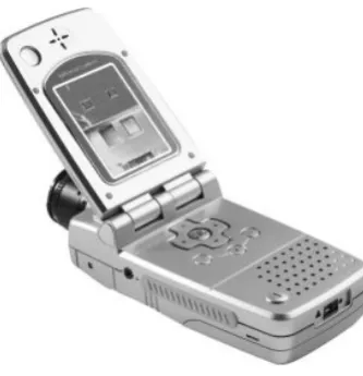
The method of the check measurement was adapted for the continuous mode of the dryer op-eration. It was not a check measurement in terms of STN 12 6013 (1995) technical standard. The thermovision method was used for measuring the surface temperature at stable-state operation of the dryer. Thermo-camera micronix mobIR M3 (Figu-re 4) enables making thermovision shots which allows for a quick and precise measurement of the temperatures on the dryer casing. The camera measures temperatures in the range from –20°C to +250°C with accuracy of 2%. The resolution of the scanning chip is 160 × 120 pixels. The camera dis-play can be used right on the spot to determine the temperatures. The camera can be connected to PC through USB 1.1 interface, the photographs can be downloaded to the computer, and precise data can be evaluated using a software. Thermocamera mobIR has a built-in memory for storing up to 100 ima- ges. The advantage of this camera resides in its small size and weight.
In selected time intervals, we recorded the param-eters of ambient air (t0, φ0), temperature of the dry-ing medium at its entry to the layer of the material t1,
and the parameters of the drying medium at the outlet from the dryer at selected points (Figure 5) of the outer casing (t2, φ2). We analysed the parameters of the drying medium through displaying them on the i-x diagram of wet air. We used the i-x diagram of wet air of up to 200°C (Chyský 1977; Vitázek 2005) containing mixing lines for natural gas (Fi- gure 8). Point 0 represents the state of the ambient air; point 1 represents the state of the drying me-dium at its entry to the layer of the dried material.
Line 0 1 represents the change of the state of ambient air after mixing with flue gases of natural gas. Line 1 2 represents the change of the state of the drying medium after passing through the layer of the dried material.
RESULTS
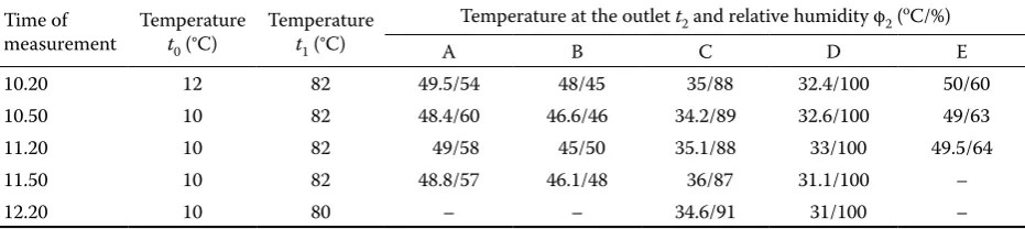
The average values of the drying medium param-eters measured at the points shown in the diagram in Figure 5 are presented in Table 1.
As the measured data suggest, the temperature and humidity of the drying medium at the outlet from the dryer varied depending on the point of measurement (A to E). However, in each given point of measurement, they did not change significantly, which means that the dryer was operated in a stable state. Significant differences exist between points A, B, and E on one side, and points C and D on the other side. In the first case (A, B, E), clearly higher temperatures and lower relative humidities of the drying medium were found, while in the second case (C, D) vice versa.
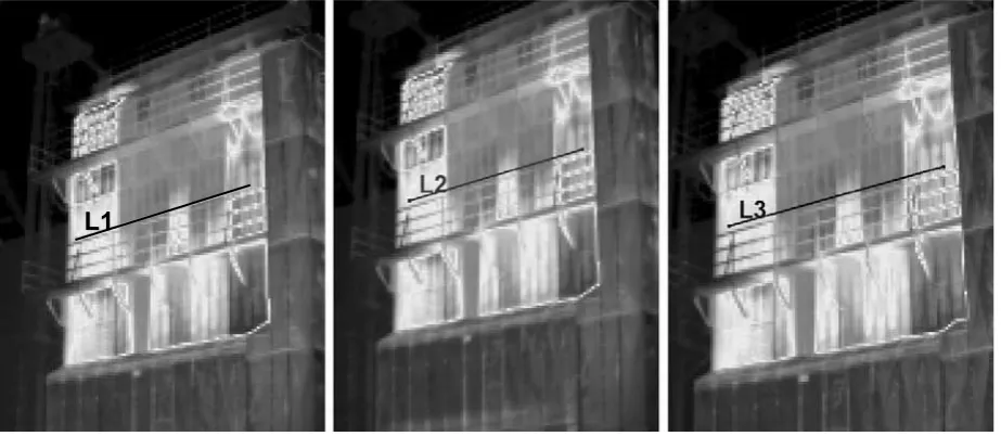
[image:3.595.65.531.652.756.2]Figure 6 shows the thermovision camera shots of the examined dryer, with lines L1 to L3 marking the points of measurement at times 10.20, 10.50 and 11.50 h, as done by the manual measurement (results in Table 1). The courses of temperatures at points L1 to L3 are shown in Figure 7 using the provided
Table 1. Measured parameters of the drying medium
Time of
measurement Temperature t0 (°C)
Temperature
t1 (°C)
Temperature at the outlet t2 and relative humidity φ2 (oC/%)
A B C D E
10.20 12 82 49.5/54 48/45 35/88 32.4/100 50/60
10.50 10 82 48.4/60 46.6/46 34.2/89 32.6/100 49/63
11.20 10 82 49/58 45/50 35.1/88 33/100 49.5/64
11.50 10 82 48.8/57 46.1/48 36/87 31.1/100 –
software. Equally, even on the basis of these data, we can suppose that the dryer was operated in a stable state.
Comparing the data from Table 1 with the data of the temperature course from Figure 7, we can state the following:
– The courses of temperature are mutually related according to the point of measurement (A to E). – The cause for the dryer casing temperature drop
(two significant drops – Figure 7) lies in silting up of the outer perforated casing, which results in reduced sizes of the openings or even their to-tal congestion. These are the obvious dark spots in the thermovision camera shots (Figure 6). For this reason, the drying medium flows through the given places at a lower speed, thus cooling off more and becoming more moist at the same time. Reducing the air flow through these places
of the dryer, however, increases the drying me-dium flow at the places not silted up, which is shown through its higher temperature and lower relative humidity (places A, B and E).
– Different flow rates of the drying medium will re-sult in an uneven drying of the material through-out the whole cross-section of the drying shaft, a lower exploitation of the drying power of the drying medium and thus a lower utilisation of the energy supplied for heating the drying medium, and also a non-uniform temperature in heating the dried material. This temperature is imposible to examine more closely due to the casing of the cooling section for the reason of drying medium recirculation.
[image:4.595.67.362.63.247.2]The selected measured states of the drying me-dium are drawn into i-x diagram of wet air of up to 200°C containing mixing lines of the fuel used. The
Figure 5. Diagram of the dryer with the points of measurement marked
The point of measurement
Figure 6. Thermovision camera shots
[image:4.595.68.530.540.741.2]Figure 8. Course of state changes of the drying medium in i-x diagram of wet air
Figure 7. Time course of temperatures at selected points according to Figure 6 65
60
55
50
45
40
35
30
25
20
Te
m
pe
ra
tu
re
(°
C
) L1L2
L3
Te
m
pe
ra
tu
re
(°
C
)
state of the drying medium denoted 2’ represents still an almost standard course. State denoted 2” already represents a course atypical for hot-air dry-ing. Althoug the humidity of the drying medium in-creased and its temperature dein-creased, its enthalpy increased.
DISCUSSION AND CONCLUSION
The thermovision shots taken in the check mea-surement on the given MC 3180 grain dryer using a thermovision camera can be used for assessing the proper operation of the dryer and carrying out or planning an early action for the maintenance of the dryer and so make the goal in its introduction. Even without a close examination, the shots men-tioned suggest different surface temperatures in the individual drying sections, and thus the necessity to eliminate the unfavourable conditions. As confirmed by further examination, silting up of the outer casing was the matter of concern.
At the time of the measurement, the weather was cloudy with occasional rain showers. At intensive evaporation of the moisture and thereby the satura-tion of the drying medium at the outlet up to the dew point (dryer so to say steams) and in combination with the outer conditions, dewing at the outer casing and sticking of the small flue-dust particles released from the dried material as well as dust particles from around the dryer whirled by wind can occur. Such situation is even more unfavourable during rain.
As other measurements and data given by the producer suggest, the MC dryers meet the required emission limits. Silting up of the outer casing of the dryer is caused by the causes already mentioned. It can be also caused by an insufficient cleaning of the material before drying (Vitázek & Tirol 2006), inconsistent handling or even reluctance to interrupt the operation of the dryer due to a high intensity of the maize supply.
The illustration of the way of the drying medium state change in i-x diagram of wet air allows for the
assessment of the drying process itself, utilisation of the added energy, and thereby the exploitation of the drying power of heated air (Vitázek 2006). In the given case, it depicts an extreme situation when the drying medium is indeed being saturated with mois-ture, but its enthalpy is rising at the same time.
The analysis of the data gained through a thermo-vision camera enables making a simple assessment of the state of the dryer outer casing and doing an immediate correction without a long and demanding observation. It allows for a continuous reaching of high performance at a very favourable consumption of heat per unit of moisture, which gives the reason for high popularity of Mathews Company dryers.
The results obtained will be subjected to further analysis and consequent measurements with the aim of assessing the effect of the dryer condition on the energy requirements and the economics of its operation.
References
Chyský J. (1977): Wet Air. SNTL, Praha. (in Czech) JUREX Ltd. (2007): JUREX Ltd. Bratislava Company
Leaf-lets.
STN 12 6013 (1995): Drying Technics. Testing of Dryers of Agricultural Materials. SÚTN, Bratislava. (in Slovak) Vitázek I. (2004): Transfer Processes at Drying – Drying
Curves. SPU, Nitra. (in Slovak)
Vitázek I. (2005): Heat Technology and Hydrotechnology. SPU, Nitra. (in Slovak)
Vitázek I. (2006): Heat Processes in Gaseous Environment. SPU, Nitra. (in Slovak)
Vitázek I., Havelka J. (2002): Enhancing the theory of drying agricultural materials. In: Proc. Int. Conf. Agrotech Nitra 2002. SPU, Nitra, 345–350. (in Slovak)
Vitázek I., Tirol J. (2006): Check measurement on grain dryer. Acta Technologica Agriculturae, 9: 97–100. (in Slovak)
Received for publication April 22, 2008 Accepted after corrections May 21, 2008
Abstrakt
Vitázek I., Tirol J. (2008): Závislosť povrchovej teploty a činnosti sušiarne. Res. Agr. Eng., 54: 176–182.
Corresponding author:
Doc. Ing. Ivan Vitázek, CSc., Slovenská poľnohospodárska univerzita, Technická fakulta, Trieda A. Hlinku 2, 949 76 Nitra, Slovenská republika
tel.: + 421 376 414 756, e-mail: [email protected]
termovíznej kamery spolu s využitím poznatkov z mechaniky vlhkého vzduchu boli odhalené a špecifikované nedo-statky v činnosti sušiarne. Výrazné rozdiely povrchových teplôt obvodového plášťa sušiarne boli spôsobené jeho znečistením, čo malo vplyv na prúdenie sušiaceho prostredia cez vrstvu sušeného materiálu. Analýza stavu sušiaceho prostredia bola realizovaná pomocou i-x diagramu vlhkého vzduchu. Uvedené poznatky umožňujú rýchlu nápravu nevhodnej činnosti sušiarne a zabezpečenie efektivity sušenia zrnín.