[ 3 5 4 ]
THE KINETICS OF LOCOMOTION
OF THE GRASS-SNAKE
BY J. GRAY AND H. W. LISSMANN
Zoological Department, University of Cambridge
{Received 7 June 1949)
(With Sixteen Text-figures)
The propulsion of an undulating grass-snake, Natrix (Tropidonotus) natrix, depends on the ability of the animal to adopt a sinusoidal form and brace the lateral surface of its body against rigid external objects (Gray, 1946). Under such conditions the forces acting normally to the sides of the body provide a propulsive force equal but opposite to the frictional forces tending to restrain the motion of the animal. The present paper represents an attempt to give quantitative expression to these con-clusions by observation of the forces acting against the body of a living snake.
THE FRICTIONAL FORCES OPPOSING SERPENTINE OR UNDULATORY MOVEMENT
The frictional forces operating against the body of a moving snake can be divided into two groups: (i) ventral friction acting between the ventral surface of the body and the ground, (ii) lateral friction acting against the sides of the body where-ever pressure is applied by the snake to an external lateral resistance. During a typical glide, each segment of the body follows in the path of the segment next anterior to itself, and consequently both frictional components act along or parallel to the path of motion.*
An estimate of the longitudinal ventral friction acting along the path of motion can be derived from observation of the forces necessary to tow the body of a dead snake rectilinearly over a variety of plane level surfaces; data of this type are recorded in Table 1. So long as the body is moving over reasonably smooth dry wood, metal or glass, the coefficient (/z.) of ventral friction (friction/weight) is of the order of 0-2—0-4. The results obtained with sandpaper of varying roughness are surprising; they show that the friction decreases with increasing roughness of ground. It is also interesting that the friction on a metal or glass surface is markedly increased by the presence of a film of oil.
The kinetics of locomotion of the grass-snake
Table i355
Substratum Glass (dry) Glass (dry) Glass (oil film) Metal (dry) Metal (dry) Metal (oil film) Wood (dry; smooth) Cardboard (smooth) Sandpaper (fine) Sandpaper (medium) Sandpaper (medium rough) Sandpaper (rough) Sandpaper (rough) Sandpaper (rough) Fibre mat Length of snake (cm.) 7 0 64 7 0 7 0 78 7 0 64 67 64 64 64 64 7° 66 66 Weight (W) of snake (g.) 7o 80 7 0 7 0 1 8 0 7 0 80 83 80 80 80 8 0 7 0 57 57Towing force in g.
Head first (TA)
28 34 9 0
2 4 6 0 > 6 o
2 7 2 0 52 5 2 4 0 35 2 0 25 35 Tail first (TP)
6 0
6 0 7 0
85 i°5
1 2 0
75
TA/W
0-40 0-42 1-3° o-34 °'33 >o-86 o-34
0 2 4
0-65
O'6s 0-50 0 4 4 0-30 0-44 op6i
tangentially to the direction of the snake's motion. The ventral friction, due to the weight of the animal, was measured by towing a dead snake of comparable size rectilinearly over the bridge. The results obtained are shown in Table 2. The con-sistency of the values obtained for the coefficient of lateral friction is probably fortuitous, but it seems reasonable to conclude that the coefficients of lateral and
[image:2.451.45.409.60.267.2]Direction of glide
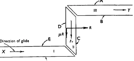
Fig. 1. Channel with two rectangular bends; the centre section (II) is mounted on a Barclay bridge registering simultaneously (i) the reaction (R) from the posterior wall D and (ii) the total friction (f-R+ Fv) acting on section II of the channel. The section of channel on the bridge was 15 cm. long.
Table 2
(Floor and walls of channel: dry metal)
Reaction (R) normal to surface (g) 45 25 20 25 18 Total friction (Fv + pR)
[image:2.451.111.344.353.459.2]356 J. GRAY AND H. W. LISSMANN
ventral friction are not greatly different from each other and are of the order of 0-2-0-4 f°r reasonably smooth surfaces.
MOVEMENT OF A SNAKE THROUGH A CLOSE-FITTING RECTANGULAR CHANNEL
In order to estimate the magnitude and distribution of the forces acting normally to the surface of the body, a dry metal channel (Fig. 2) containing two rectangular bends was employed, both walls of each of the three sections (I, II and III) being,
B Sceel lamina
Fig. 2. Channel with two bends, the walls being mounted on vertical steel strips registering forces acting normally to the walls of the channel. When the snake was gliding towards Y, pressures were exerted against the walls B, D and F; no pressures were exerted against walls A, C and E. When the snake was gliding towards X the distribution of pressures was reversed.
Fig. 3. Diagram showing the general distribution of all external forces acting on a snake when gliding through a channel with two rectangular bends. F1, F2 and F3 represent the ventral sliding friction
acting on each of the three sections of the channel. Rlt R2 and R3 represent the pressures
exerted by walls B, D and F normal to their surfaces, /ii^, pR2 and iiR3 represent the lateral
friction associated with i?x, i?2 and R3.
The kinetics of locomotion of the grass-snake 357
"From the body of a snake gliding from X towards Y were invariably exerted againstthe 'posterior' walls B, D and F, no pressures being exerted against the 'anterior' walls A, C and E. When the snake glided from Y towards X, the lateral pressures were invariably transferred to walls A, C and E. In every case, the total length of snake enclosed by sections I and III was greater than that in section II and the pressure exerted against the wall of section II was considerably greater than that against the wall of section I or section III. Reference to Fig. 3 shows that the normal reaction (i?2) exerted on the snake by the wall D of section II provides a
measure of all the frictional forces acting against the regions of the body enclosed by sections I and III, the total frictional force of these two sections being composed of the ventral components Fx and F3, together with the lateral friction associated with
14
17
V
-25
-12-20
1 0
[image:4.451.57.393.230.428.2]-(N)
Fig. 4. Diagram showing the forces actually elicited from the walls of a zigzag channel, (i) shows the forces acting normally to the surface of the channel; (ii) shows the total friction acting against the body. The sum of the normal forces should equal that of the frictional forces; the figures actually recorded were normal forces 68 g. and frictional forces 58 g.
the forces (Rx and R3) acting normally to the walls. Similarly, the sum of the forces
R± and R3 measures the total friction acting against section II of the channel. Finally, the total ventral friction (F1 + F2 + F3) is related to the weight of the animal (W) by the coefficient of ventral friction.
During a steady glide three equations must be satisfied:
(i)
(ii)
(iii)
358 J. GRAY AND H. W. LISSMANN
78 g., the forces acting normally to the walls of sections I, II and III were found to be io, 35 and 10 g. respectively, making a total of 55 g. compared with the theoretical estimate of 52 g.
Similar results were obtained when a snake was allowed to glide through a zigzag channel of the type shown in Fig. 4, one section being mounted on a bridge regis-tering, simultaneously, pressures normal to its walls and the total friction acting along its length. The lateral and antero-posterior displacements of the bridge were amplified by mechanical levers whose movements, together with the position of the snake in the channel, were recorded photographically from the moment the snake's head entered the recording section until the tip of the tail had passed through. Fig. 4 is constructed from data of this type. For a snake weighing 80 g., the total force acting normally to its surface was found to be 68 g. On the basis of a coefficient of friction of 0-4, the ventral friction should have been 32 g. and the lateral friction 27 g., making a total of 59 g.; the total observed friction was 58 g. Undue emphasis must not be laid on the close agreement between the observed and calculated values of total friction; complete agreement between theory and observation involves an equality between the total forces acting normally to the body and the total friction; in fact, the observed forces acting normally to the body were 68 g., whereas the observed friction was 58.
THE FORCES EXERTED BY A SNAKE WHEN GLIDING PAST A SERIES OF VERTICAL PEGS
Under natural conditions, a grass-snake glides forward by bracing the sides of its body against grass, stones or other projections from the surface of the ground, the reactions from these projections yielding a resultant force equal but opposite to the ventral friction operating between the body and the ground.
The magnitudes and directions of the reactions from external objects can be determined by allowing the animal to exert its effort against a series of relatively heavy cylindrical pendulums whose displacements can be measured photographically as the animal glides along. The force exerted by the snake against each pendulum (Fig. 5) has two components—one acting normally to the surface of the cylinder and the other (lateral friction) acting tangentially to its surface.
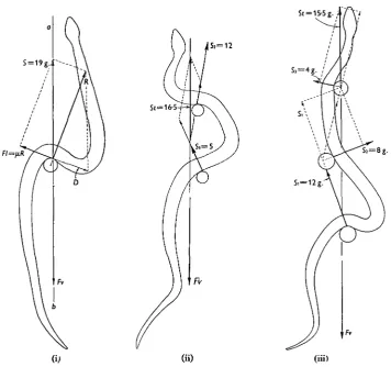
As observed by Wiedemann (1932), a snake propels itself past a single cylindrical peg by throwing its body into an S-shaped bend and applying pressure to the anterior surface of the peg. Fig. 6 (i)* of the present paper shows this typical form, together with the magnitude and direction of the force exerted by a single pendulum against the body of the animal. For a snake weighing 85 g. and gliding over a smooth glass surface the total reaction (5) from the pendulum was 19 g. and was directed approximately along the axis of forward motion of the snake. As shown in the figure, the reaction (R) which acts normally to the surface of the body has two components; one (D) equal and opposite to the friction (Fl) acting at the surface of the pendulum, and the other (S) equal but opposite to the ventral friction (Fv). In Fig. 6 (ii) the same snake is seen gliding past two pendulums, the total reaction from one peg
The kinetics of locomotion of the grass-snake 359
being 5 g. and from the other 12 g., yielding a resultant (Si) of 16-5 g. along the axis of motion. When operating against three pendulums (Fig. 6 (iii)), the resultant reaction from the pegs yielded a forward thrust along the axis of motion of approxi-mately 15-5 g.; when operating against a larger number of pendulums (Fig. 7) the resultant forward thrust varied from 17 to 22 g. These values represent the compo-nent of friction acting along the axis of motion and indicate a coefficient of ventral friction not less than 0-2.R E
N (normal pressure)
5 (resultant force) / V \
[image:6.451.103.351.166.493.2]L.X J
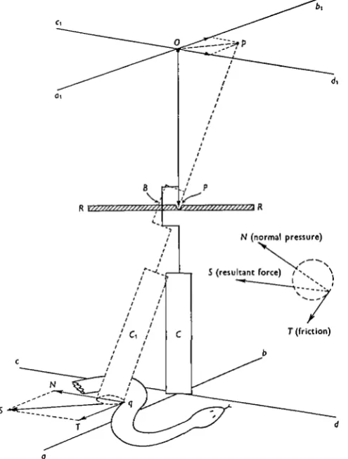
Fig. 5. Apparatus for determination of the force exerted by a snake when gliding past the surface of a vertical cylindrical peg. A relatively heavy cylinder (C) is suspended by a pin-pivot (P) to a rigid horizontal bar (RR); the cylinder can rotate about the pivot with respect to both its horizontal transverse axes. Rotation about its vertical longitudinal axis is restricted to 1800 after which the arm B engages with the transverse bar. Above the pivot is a long rigid pointer PO, whose upper end lies at the intersection of two horizontal rectangular axes (aj>i, Cid^). When undisturbed, the centre of the base of the cylinder lies at the intersection of axes {ab, cd) which are parallel to ajbi and c^. When the snake engages with the base of the cylinder, the latter is displaced with reference to the axes ab and cd\ simultaneously, the pointer is displaced with reference to aj>i and C\di\ the line Op is parallel and proportional to the resultant force (S) exerted by the snake on the cylinder.
Fig. 7 shows that as the number of external resistances is increased the total force which the snake exerts transversely to its axis of motion also increases, whereas the
360 J. GRAY AND H. W. LISSMANN
resultant forward thrust remains relatively constant. The records also show that the pressure exerted against any particular resistance may vary greatly as the snake moves along, although the pressures exerted by the anterior end of the animal are usually relatively small.
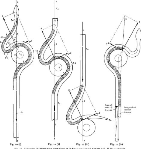
If a peg were perfectly smooth, the reaction from its surface would pass through the centre of curvature of the peg and consequently the line of action of the ventral longitudinal friction must also pass through this point. Friction inevitably acts at the surface of the peg, and the conditions for glide can only be satisfied when the total reaction from the peg forms a tangent to a circle concentric with the surface of the peg and having a radius* depending on the coefficient of lateral friction and on the radius of curvature of the peg. These conditions are satisfied in Fig. io,t where the total ventral friction (Fva+Fvp) is tangential to the frictional circle at g; the centre of pressure between the snake's body and the peg lies at p, whilst the total reaction (S) from the peg is equal but opposite to
(Fva+Fvp).
Since the forward glide is dependent on the total ventral friction forming a tangent to the friction circle of the peg, it is of interest to consider the extent to which this funda-mental requirement can be satisfied by appropriate muscular activity on the part of the animal. So far, no experimental data are available, but it seems reasonable to suppose that the animal can control the line of action of the total ventral friction by bracing its body against static lateral friction between the body and the ground. This principle is illustrated by Fig. 10 (iv) where the line of action of the longitudinal friction passes through the centre of the peg; by bracing an adequate length of its body against static lateral friction, the total ventral friction has become tangential to the friction circle of the peg.
THE PATTERN OF MUSCULAR EFFORT EXERTED BY A GLIDING SNAKE
If the points of application, directions and magnitudes of all the external forces acting against the body of the animal can be determined, it is possible to deduce the pattern of muscular activity involved; at any instant, the muscles acting uniaxially about any vertebral joint must develop sufficient tension to produce about the centre of rotation of the joint a moment (over and above that required to balance the effect of antagonistic muscles) equal but opposite to the sum of the moments exerted by the relevant external forces. Any redistribution of muscular effort automatically involves a redistribution of the pressures exerted by the animal against its external environment. At the same time, however, no muscle—however great may be its tension—can supply useful propulsive energy unless the muscle shortens as progres-sion proceeds.
Applying these principles to a snake gliding through a zigzag channel composed of two rectangular bends (Fig. 8 (i)),| two groups of muscles shorten as each region of the body passes a bend. On approaching a bend to the right, the muscles of the right side (yr in Fig. 8 (i)) shorten as the region of the body concerned enters the bend, whilst those of the left side (7/) are stretched; on leaving the bend the muscles (5Z) of the left side shorten whilst those of the right side resume their normal length; when • If the radius of the peg is r, that of the 'circle of friction* is r sin 0, where 8 is the angle whose tangent is equal to the coefficient of lateral friction (fi). See Fig. 10, Folder III.
The kinetics of locomotion of the grass-snake 361
passing a bend to the left these changes in length are reversed. As the snake glides forward through the channel shown in Fig. 8 (i), four groups of muscles shorten, viz. 5/, jr, 137 and 15/, and since a muscle can only perform useful external work when it shortens in length, the energy for propulsion can, theoretically, be derived from one or more of these four groups, two of which are located on the left side of the body and two on the right side. In order to determine which of these groups act as prime movers for the animal's progression, it is necessary to consider the distribution of external pressures (against the walls of the channel) which arises in response to activity in each of the four groups of muscles. For this purpose the snake's body can be represented by three units (I—III) as in Fig. 8 (ii). If the muscles (Afrx) on the
inner side of the leading bend develop tension, the region (I) of the body anterior to the hinge / is braced against wall B; similarly, if the muscles (Mr2) on the right of hinge K shorten, the posterior unit (III) is braced against wall F. On the other hand, if the muscles on the left side of the body (e.g. Mlx and Ml2) develop tension, sections I and III are braced against walls A and E respectively. The experimental results show clearly that the animal exerts its effort against walls B and F only, and consequently the muscles of the right side are acting as the prime movers for pro-pulsion, whereas those of the left side can be regarded as responsible for the control of the animal's shape and for guiding the body smoothly along the floor of the channel.
The relative tension of the muscles operating about each vertebral joint as deter-mined from the sum of the moments exerted by the external forces is shown in Fig. 8 (iii). The maximum tension is developed by the muscles opposite the centre of pressure (b) of the force exerted against wall D of the channel; the whole of the propulsive energy is derived from the muscles Mrx and Mr2, the former group shortening under decreasing tension and the latter shortening under increasing tension. As explained in the Appendix (p. 365), a channel containing two rectangular bends represents the basic requirements for a smooth glide, for it provides three effective points d'appui against which the muscles can exert effective leverage. The muscles must develop tension on the side of the body towards which the animal turns when entering the second bend of the channel (i.e. the bend lying nearest to the head of the animal); in every case, the animal exerts pressure against the ' posterior' walls of the channel.
When a snake is gliding round three bends (Fig. 9 (ii)),* it develops its effort against four points d'appui {a, b2, e and/) instead of against three (as in Fig. 9 (i)), all four being situated on the posterior walls (F, D, B and H). The sum of the moments of the external forces about each joint shows that the muscles on the ' inner' (i.e. left) side of the third bend have developed tension. Similarly, when negotiating four bends as in Fig. 9 (iii) the snake utilizes five points d'appui, again, all situated on the pos-terior walls (F, D, B, H and K), and in this case the sum of the moments of the external forces shows that the muscles on the 'inner' (i.e. right side) of the fourth bend are under tension.
• See Folder II.
362 J. GRAY AND H. W. LISSMANN
The general mechanism of propulsion through a zigzag channel containing several bends can be summarized by noting that, as the animal moves into a new section of the channel, the muscles shorten on the side of the body towards which the head turns to negotiate the bend, and at the same time these muscles develop tension against the resistance offered by the 'inner' or more 'posterior' wall of the channel. The active muscles lie on the inner side of each bend; the only exceptions are those situated in the most posterior bend. From a physiological point of view the progress of the animal can be visualized in terms of unilateral waves of muscular posture and tension passing alternately down each side of the body. The form of the waves is determined by the form of the channel, whereas the distribution of muscular tension is, within certain limits, under the control of the animal; for any particular instance, it can be determined by precise observation of the distribution of the forces exerted against the walls of the channel. The distribution of the external forces shown in Fig. 9 is in accordance with the experimental facts; at the same time their magnitude and points of application have been arbitrarily adjusted to yield a state of dynamic equilibrium. The figures should not therefore be regarded as more than a diagrammatic illustration of the general mechanism involved. A more precise relationship between the muscular effort and distribution of external forces involves a consideration of the vertebral column as a series of levers and is given in the Appendix.
THE PATTERN OF MUSCULAR EFFORT WHEN GLIDING PAST A SERIES OF RIGID PEGS
The muscular effort required to glide past a series of rigid pegs is fundamentally similar to that required to glide through a zigzag channel; it is, however, less easy to obtain a complete picture of all the external forces acting against the body and there-fore less easy to deduce the underlying pattern of muscular effort.
Fig. 10* shows, diagrammatically, the distribution of muscle tension (as derived from the sum of the moments of external forces) of a snake gliding past the surface of a single peg; the strain falls on the axial muscles lying on the side of the animal which is in contact with the peg. The energy for propulsion is derived from two groups of muscles; those which shorten between the points c and d, thus drawing the posterior region of the body forwards, and those which shorten between e and/, thus pushing the anterior end of the body forwards. As the animal glides forward the reaction from the peg remains unchanged, but the effort of the muscles posterior to p decreases, whereas that of the muscles anterior to p is increased (see Fig. 10 (ii) and (iii)).
The muscular effort necessary to glide past two pegs is shown in Fig. 11. As the snake applies its body to the second peg, the muscles on the side of the body in contact with this peg develop tension, but this can only happen if the snake simul-taneously alters the pattern of effort being exerted by the group of muscles which had previously been exerting their effort against the first peg. The nature of this change depends partly on the position of the two pegs relative to the line of action of the
FI=fiR
St = 15-5 g. /
[image:12.451.53.410.138.472.2]Si=12
Fig. 6. Tracings from cinematograph records showing the form of the body and the external forces in grams operating against the body of a snake when gliding past one, two and three pendulums. In (i), the reaction (R) normal to the surface of the pendulum has two components D and S; D is equal but opposite to the lateral friction (Fl= pR) of the pendulum, while S is equal but opposite to the ventral friction (Fv) acting along ab. In other words, the total reaction (S) from the pendulum is equal but opposite to the ventral friction. In (ii), the resultant (St) of the reactions (Si and 52) from the two pegs is equal but opposite to the total ventral friction (Fv). Similarly,
The kinetics of locomotion of the grass-snake 363
ventral friction, but it is partly under the control of the animal; it cannot be fully determined without more precise information concerning the points of application of the pressure against the two pegs than is at present available.
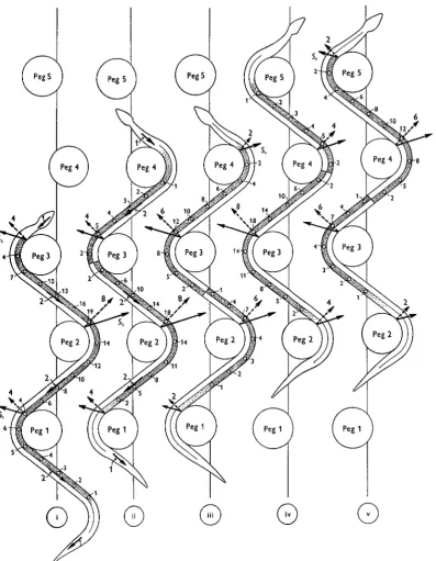
When a snake is gliding past a series of pegs the range of effective muscular effort becomes still wider and could only be examined by very extensive experimental analysis. The fundamental nature of the effort can, however, be visualized from Fig. 12, in which the resultant ventral friction is assumed to be distributed as in Fig. 12 (i), and where the points of application of the pressures exerted by the pegs are assumed to be known. When using pegs 1-3 only, as in Fig. 12 (i), the strain falls exclusively on the side of the body towards which the head has turned to gain contact with the most anterior of the three pegs. Thus, in Fig. 12 (i), the strain is on the right side, just as in Fig. 9 (i); substantially the same pattern of muscular effort persists until the anterior end of the animal begins to glide past the surface of peg 4 (Fig. 12 (ii)); at this point the muscles of the left anterior region of the body begin to develop tension. As soon as pressure is exerted against peg 4 (Fig. i2(iii)), the wave of activity in the muscles of the ieft side spreads backwards, and this process continues so long as the pressure against peg 4 is increased. As the snake glides forwards to gain contact with peg 5, the muscles of the right anterior side develop tension whilst those of the left anterior side relax (Fig. 12 (iv)). When the tension in the right anterior muscles increases still further, pressure is exerted against peg 5 (Fig. 12 (v)), and the wave of activity on the right side spreads farther backwards along the body. The progression of waves of uniaxial tension alternately down the left and right sides of the animal is illustrated by Fig. 12 (ii-v).
The fundamental principle of peg gliding is clearly the same as that of gliding through a zigzag tube, but the precise pattern of the muscular effort is much more variable. In physiological terms, the glide can be regarded as due to unilateral postural and tensional waves passing alternately down each side of the body. The form of the postural wave is determined by the position of the pegs; the form of the tensional waves is, to a considerable extent, under the control of the animal, and in nature may reasonably be expected to be such as to distribute the total load equitably between the total available musculature.
THE FORCES EXERTED DURING EXTERNAL RESTRAINT
The forces exerted by a freely gliding snake represent only a fraction of those developed when the animal is under restraint. If an isometric lever is attached to the animal at a point immediately posterior to the region which is gliding past the surface of two rigid pegs, the snake continues to glide until the tension of the lever rises to two or three times the weight of the animal (Fig. 13 (i)), after which the tension slowly declines, exhibiting as it does a variable amount of fluctuation. Even greater forces can be exerted if the snake is subjected to a backward pull sufficient to make the animal slip backwards past the pegs; under such circumstances the animal can exert a tension equal to four or five times its own weight. These responses are almost certainly of proprioceptor origin.
3
64
J. GRAY AND H. W. LISSMANNregion of the body in contact with the pegs, it can be attached to the tail of the animal. In this case a well-marked rhythmical response is superimposed on the sustained pull against the pegs (see Fig. 13 (ii)). The rhythmical response is due to the action of the axial muscles lying posteriorly to the pegs; these muscles throw the
Fig. 13. Tensions set up by a grass snake (83 g.) under restraint, (i) The snake gliding past two rigid pegs is restrained by a string attached a short distance behind the last peg. Fluctuating muscular tension is developed and is maintained for a considerable period, (ii) When the restraining force is applied to the tip of the tail the development of rhythmic tensions is associated with an undulatory pattern of small wave-length and amplitude which spreads in a posterior direction over the body.
Fig. 14. Tensions recorded from the tip of the tail of a swimming grass snake (67 cm.). At t the body of the snake was allowed to engage against two rigid pegs. This was accompanied by cessation of swimming, while the pull which the snake exerted against the pegs was more than twice its body weight. At "<• the pegs were removed and the snake resumed swimming.
posterior part of the body into a series of undulations of short wave-length and amplitude, and as the undulations develop the total tension rises. As the undulations die away the tension falls; this process is repeated several times.
The kinetics of locomotion of the grass-snake
normal swimming movements. These responses recall those of a quadruped, such as a toad, in which diagonal ambulatory movements replace bilateral swimming as soon as the limbs can engage with the ground and elicit an adequate reaction (Gray & Lissmann, 1946). Similarly, the swimming movements exhibited by the front end of a snake whilst its posterior region is pulling against rigid pegs recalls the behaviour of a nemertine under comparable circumstances (Lissmann, vide Gray, 1939).
APPENDIX
The relationship between uniaxial muscular tension and the pressures exerted against external resistances
Although the general patterns of muscular effort can be deduced from an accurate determination of the pressures exerted by the snake against the walls of a zigzag channel, it is perhaps of greater functional interest to consider the converse problem of how the tension of the muscles results in a forward thrust capable of driving the animal forward; thus, in Fig. 8 the tension of the muscles of the right side must be applied in such a way as to yield a resultant external force equal but opposite to the total ventral friction (Ft + F2 + F3
(Fig. 15 0)).*
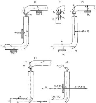
The relationship of the propulsive force to the tension of the muscles can be visualized by means of two simple but important mechanical principles: (i) When a muscle develops tension across a vertebral hinge, it operates both regions of the body as levers; it applies equal but opposite couples to the structures lying on each side of the hinge, the other arms of the couples being due to compression forces acting across the hinge (see Gray, 1946). (ii) The mechanical effect of a couple is the same as that of any other couple of equal moment and similar sign acting in the same plane. These principles are applied to a snake when gliding past two rectangular bends by dividing the animal into two regions (xyj and
jzu) through the hinge;' (Fig. 15 (i)) and considering the effect of shortening the muscles (Mr) which operate on the right side of this hinge. For the sake of simplicity, it can be
assumed that contact between the body and walls B and F is restricted to the points a and c respectively. When the muscles (Mr) tend to shorten, the body encounters resistances applied by the walls B and F, and the muscles therefore develop tension; a clockwise couple (Q71!, Fig. 15 (ii)) is applied to the region xyj and an equal but anti-clockwise couple
(C2T2) to jzu. The clockwise couple applied to xyj can operate this region of the body as
a lever in two ways, (i) by using wall B at c as a fulcrum and (ii) by using the hinge j as a fulcrum. When operating in the first capacity (Fig. 15 (iii)) the couple QTi is equivalent to a couple PXQ-L applied at c and at;'; the force Px exerted against wall B elicits an equal but
opposite reaction (i?j), and consequently the resultant force exerted on xyj is Q1 operating
at the hinge and forming a tractive force pulling against the frictional resistance (F2) which
acts along the axisyjz. On the other hand, when the effort of the muscles is exerted against a fulcrum provided by the hinge at j , the clockwise muscular couple exerted on xyj is equivalent to the couple G-jH^ (Fig. 15 (iv)), where G1 is a propulsive force equal but
opposite to the frictional resistance (Fj) acting along the axis xy, whilst Hx is a force acting
against the hinge. The combined effect of the muscles on xyj is therefore to provide propulsive forces which balance the ventral friction (Fi) along xy and contribute towards the force required to overcome F2. The muscles cannot, however, produce these effects without, at
the same time, exerting the force Ht against the hinge (Fig. 15 (v)) and exerting an
anti-clockwise couple (C%T2) against the region of the body (jzu) behind the hinge. The
366 J. GRAY AND H. W. LISSMANN
anti-clockwise couple also operates jzu as a lever in two ways: (i) by using the wall F as a fulcrum at a, thereby exerting the couple P3Q3 (Fig. 15 (iii)); the force P3 elicits an equal
but opposite reaction (R3) from wall F, whilst Q3 constitutes a propulsive force along the axis zjy, thereby operating against Ft; (ii) by using a point t (Fig. 15 (iv)) as a fulcrum and
exerting a couple G2H2, where G2 is a propulsive force equal but opposite to F3 and where H2 is a force exerted at t and parallel to Hv The muscles can therefore provide propulsive
forces equal but opposite to Flt F2 and F3 if, at the same time, wall D provides a reaction
(i?2) equal but opposite to the resultant (P2) of H± and H2 (Fig. 15 (v)). The above analysis
involves two artificial simplifications: (i) it is assumed that the body of the snake is braced against walls B, D and F at three points only, (ii) that the walls of the channel are perfectly smooth. Under natural conditions the distribution of pressure between the body and the walls of the channel is under the control of the animal. By appropriate muscular effort the whole of the force required to overcome F2 can be transferred to wall B or wall F ; this
involves a movement of the centre of pressure along wall D. If the walls of the channel are not perfectly smooth the effort of the muscles must be increased in order to overcome the resistance due to lateral friction; otherwise the pattern of effort of the muscles remains essentially unchanged.
A channel containing two rectangular bends represents the basic requirements for a smooth glide, for it provides three effective fulcra (a, b, and c in Fig. 15) against which the muscles can exert their effort, the body of the snake constituting a fundamental propulsive unit consisting of two curved levers operated by the muscles lying on the side of the body towards which the more anterior of the two bends is inclined. Once this basic propulsive unit has been established, additional and somewhat simpler units come into action when-ever the snake turns past the third, and each successive, bend in the channel. The nature of these additional units can be visualized from Fig. 16*; the only difference from the unit already described lies in the fact that only the more anterior of the two levers is curved, the more posterior lever being straight. In all cases an additional propulsive unit is operated by the muscles on the inner side of the bend in the channel. Fig. 16 (i) shows the forces exerted by a double-bended right-handed unit against the walls of the channel when the unit is operating by itself, whereas Fig. 16 (iv) shows the reactions from the walls when the original double unit is operating with a new left-hand unit such as that shown in Fig. 16 (ii). Fig. 16 (iv) shows that the muscles of the anterior unit are not exerting a force at d against the wall A of the channel but against the muscles of the posterior unit; when the new unit becomes operative, the reaction from wall B moves forwards from c to e (see Fig. 16 (iv)). The formation of successive propulsive units and their effect on those already in operation is shown in greater detail in Fig. 9. In Fig. 9 (i) two rectangular bends are occupied by the animal, and since the more anterior bend is directed towards the right, the whole of the strain falls on the muscles of the right side; these exert their effort against the walls of sections I, II and III at a, bt and c respectively. In Fig. 9 (ii) the head of the animal
has passed the third bend, and since this is directed towards the left, the muscles on the left side encounter resistance when the body is in contact with the left wall of the channel at / ; at the same time, these muscles encounter resistance at e and d. As this resistance increases the force exerted against d becomes equal but opposite to that exerted by the posterior propulsive unit at c, and consequently the reaction from the wall at c disappears— whilst shearing forces act across the vertebra at the level cd; in other words, at this level the active muscles of the leading left-hand propulsive unit are pulling against those of the posterior right-hand unit and vice versa. In Fig. 9 (iii) the head of the snake has passed the fourth bend into section V and a third propulsive unit, operated by the muscles of the right side, has come into action with its muscles exerting their effort against the walls of
Fig. I I . Diagram illustrating the general pattern of muscular effortwhen gliding past two rigid pegs. T h e figure shows the pattern necessary to overcome a ventral frictional force (Fv) acting posteriorly to both pegs; this force is
in equilibrium with the reactions ( S and S,) from the pegs. Note that the strain falls on the muscles on the side of the body in contact with the pegs.
Fig. 12. Diagram illustrating the general type of muscular effort required to glide past a series of rigid pegs. In (i) the snake is exerting its effort against pegs 1-3. The magnitude and direction of the ventral friction are indicated by the length and direction of the arrows lying along the axis of the body. The resultant of all these forces is the same in (i)-(v). The point of application and direction of the total reactions from each peg are shown by the arrows SrS5; the forces acting normally to the surface of the pegs are shown by the dotted arrows. The coefficient of lateral friction is 0.5. All the external forces are in equilibrium. The muscular effort is obtained by taking the moment of all these forces about successive vertebral joints; the value of these moments is shown (approxi- mately) by the figures beside each circle, and recorded on the appropriate side of the body. In (i) the whole of the strain falls on the muscles of the right side, since it is towards this side that the animal has turned to engage its body against peg 3. . I n (ii) the snake has glided forward turning its left side against peg 4. No pressure is, as yet, applied to peg 4, but the ability to turn towards the left involves shortening of the muscles of that side. I n (iii) the muscles of the left side are exerting pressure against peg 4 ; this involves an increase in the pressure exerted against peg 3 and a reduction of those against pegs 2 and I . I n (iv) the snake has glided forward and has turned to the right to gain contact with peg 5, thus involving activity in the muscles of the right side. Simultaneously, the animal has lost contact with peg I ; the pressure against peg 2 has decreased, whilst the pressures against
pegs 3 and 4 have increased. In (v) the snake is exerting pressure against peg 5, and this involves a change in the pressures against pegs
[image:20.1004.506.904.60.572.2] [image:20.1004.62.253.105.538.2]Fig. 10 (i) Fig. 10 (ii)
I
bFig. s o (iii)
r-t
Fig. 10 (iv)
Fig. 10. Diagrams illustrating the mechanism of gliding past a single circular peg. If the coefficient of lateral friction between the body and the peg is p, the total reaction (S) from the peg must form a tangent to a circle, concentric with the surface of the peg, of radius r sin 9, where r is the
[image:21.574.53.523.53.550.2](ii)
~$j?
c1
R,
(iii)
Fig. 15. Diagram illustrating the origin of propulsive forces when the axial muscles act against the walls of a rigid channel containing two rectangular bends, the more anterior of which is directed towards the right side of the animal. T h e frictional forces restraining forward motion are F,, F,
and F3 acting along the axes xy, y z and zu respectively. T h e snake is divided into two parts at the hinge j, the muscle (MY) acting on the right side of the hinge; the snake's body is in contact with the walls B, D and F of the channel, and it is assumed that pressures against B and F can be exerted only at a and c respectively (i).
When the muscles at j develop tension against the restraints imposed by the forces F,, F,
and F3 and by the walls of the channel they exert a clockwise couple (TICl, fig. 15 (ii)) against the section (xyj) of the snake anterior to the hinge, and an equal but anti-clockwise couple (T,C,) against the section (jzu) posterior to the hinge. As shown in fig. 1 5 (iii), the couple TICl is equivalent to a couple QIPl having similar direction and equal moment to TICl; PI elicits an equal but opposite reaction (R,) from wall B at c, and consequently the resultant force acting on xyj is Q, acting along the axis yz and operating against F,. Similarly, the anti-clockwise couple T,C, acting on jzu is equivalent to a couple Q,Pa, in which Q, represents a forward thrust along yz, whilst P3 elicits from wall F a reaction (R3)'equai and opposite to P3 at a. As shown in (iv) the muscles acting about j can exert their effort against the forces Fl and F3 as well as against F,; in this case the couple acting on xyj is equivalent to GIHl, thus providing a forward thrust against F,, whilst the couple acting on jzu is equivalent to G2H,, thus providing a forward pull against F,. As shown in (v), a force Hl (equal to F,) acts against the hinge, and a force Hz (equal
to F 3 acts at t ; the resultant of these two forces is a total pressure P, exerted against wall D at b. T h e wall yields a total reaction (R,) equal but opposite to P,.
Wall
F,
Wall H
(ii)
I Wall A
Wall G
.,.
Wall F
t Wall B
[image:22.977.571.911.53.548.2] [image:22.977.69.398.81.436.2]The kinetics of locomotion of the grass-snake 367
•Sections V and IV, at i and h, and against the muscles of the more posterior propulsive unit at the level fg. It will be noted in Fig. 9 (iv, v) that the centres of pressure between the body and the walls of the channel are situated towards the anterior end of each channel (just before the next bend in the channel is reached). This is in conformity with the positions actually observed when the snake moves through a channel somewhat wider than its own body and when the snake is made to exert its effort against a wall composed of a series of independently mounted elastic strips of metal; in the latter case the greatest deflexion is observed at points similar to those indicated in Fig. 9 (iv, v).
SUMMARY
1. T h e coefficient of sliding friction between the ventral or lateral surface of a grass-snake varies from 0-2 to o-6 according to the nature of the surface over which the animal is moving.
2. T h e distribution and magnitude of the external forces acting against a moving snake has been determined for (i) an animal moving through a close-fitting zigzag channel, and (ii) an animal gliding past one or more rigid pegs. T h e pattern of muscular effort required for these two types of motion is described. Forward move-ment is due to the operation of the vertebral column as a series of levers.
3. For a freely moving snake the propulsive force is of the order of one-third of its total body weight; when motion is artificially restrained a grass-snake can sustain a pull of four or five times its own weight.
4. The circumstances under which a snake can exhibit typical terrestrial locomo-tion as opposed to the movements exhibited in water are fundamentally similar to those of a quadruped such as a toad.
REFERENCES
BARCLAY, O. R. (1946). J. Exp. Biol. 23, 177. GRAY, J. (1939). Proc. Roy. Soc. B, 128, 28. GRAY, J. (1946). J. Exp. Biol. 23, 101.
GRAY, J. & LISSMANN, H. W. (1946). J. Exp. Biol. 23, 133.