Abstract— WiMAX OFDM-based systems are characterized by their ability to provide high data rate with low BER (bit error rate) at low SNR (signal to noise ratio). In this paper, we demonstrate the performance of the system under real fading IEEE standardized channels; originally known as the Stanford University Interim (SUI) channels for broadband wireless access. The six channel models characterize most possible environmental fading effects. They define three terrain channel types; soft fading environment (SUI 1 and SUI 2), intermediate fading environment (SUI 3 and SUI 4) and harsh fading environment (SUI 5 and SUI 6). Each fading environment is thus characterized by two channels representing the possible extremes so that the actual fading channel falls in between. All mandatory WiMAX parameters such as BPSK, 16-QAM, Reed Solomon encoding, to name a few, were used in the simulation of the system and their results in terms of BER versus SNR plots were analyzed. Our focus is on optional parameters in the Standard such as 256-QAM, 512 subcarriers and, best of all, promising MIMO smart antenna application. Conclusions are extracted from simulation results
that specify best configuration of WiMAX system. So in this
work, we present the results of the 1x2, 1x4 receiver diversity and 2x2, 4x4 MIMO with 512 subcarriers and show system performance improvement in both the data rate and BER-SNR relationship. We compare those results with the mandatory reference model of the IEEE 802.16d standard.
Index Terms—WiMAX-OFDM, MIMO, SUI channels, Fading, Smart Antennas.
I. INTRODUCTION
The term WiMAX means: Worldwide Interoperability for Microwave Access. WiMAX technologies are widely accepted as a cost effective and reliable solution for delivering wireless broadband services [1]. WiMAX is based on a next generation all IP core network, which offers low latency, advanced security, QoS (Quality of Service), and, in the case of mobility, worldwide roaming capabilities [2].
Manuscript received July 26, 2011; revised August 7, 2011.
Osama W. Ata is with the Department of Electrical and Computer Engineering, Faculty of Engineering and Technology, Palestine Polytechnic University, Hebron, Palestine (phone +970-2-2987978). He is currently on leave to the Department of Electrical and Computer Engineering, Villanova University, 800 E. Lancaster Avenue, Villanova, PA 19085, USA. (E-mail: [email protected]).
Nemer A. M. Al-Amleh graduated with a B.Sc. in Electrical Engineering, with high honors, from Palestine Polytechnic University in July 2010. (E-mail: [email protected]).
WiMAX comes as an alternative to cable and digital subscriber loop (DSL). WiMAX is based upon Orthogonal Frequency Division Multiplexing (OFDM) that provides very good spectral efficiency and resistance to multi-path propagation. It targets frequency bands below 11 GHz [3], can deliver data rates of 75 Mbps, cover ranges of 30km, and can provide secure delivery of content and support mobile users at vehicular speeds [4].
OFDM can significantly simplify the equalization problem. A frequency selective channel is approximately flat in each sub-channel. Instead of single carrier with high data rate, OFDM uses more subcarriers modulated with lower data rates. This leads to small channel variations in every sub-channel. Therefore the inter-symbol interference is reduced or even diminished [5].
In the literature, Marko Djurdjevic et al, in his paper, introduced the standard based WiMAX downlink model for testing future improvements in data transmissions over the Stanford University Interim channels [5]. Bikash C. Singh et al focused on Simulation based analysis of IEEES02.16-2004/WMAN-OFDM PHY layer. Specifically the paper aimed at quantifying the improvement of the PHY layer performance, evaluated in terms of bit error rate (BER) versus Signal to Noise Ratio (SNR), with respect to the different channel models [4].
Other papers investigated for the optional parameters in the Standard such as MIMO-OFDM for further more improvements on data rate and performance of WiMAX. Specifically, Pranesh Shah and Kaylan Mondal showed, in their paper, the performance of OFDM-based WiMAX utilizing Alamouti’s two transmitters and one receiver diversity concept under frequency selective Rayleigh fading and maximum Doppler shift channel fading conditions [3]. Jafarian and Rjabzadeh presented a simulation model for fixed WiMAX with MIMO 2x2 and 4x4. The authors proposed a new approach that eliminated co-space interference (CSI) and the inter-symbol interference (ISI) by using the Singular Value Decomposition (SVD) method [6]. Gutierrez et al presented in their paper a combination of transmit antennas selection [M=2, 3, 4] with a fixed number of receive antennas of N = 2 using the space time block
Application of MIMO Smart Antennas into
WiMAX-OFDM System in Real Fading IEEE
Standardized Channels
coding (STBC) technique to improve the data rate and the performance of WiMAX system [7]. Kobeissi et al presented, in their paper, a simulation of mobile WiMAX 802.16e system by using the Golden Code, claimed to be the best full-rate full-diversity 2x2 STC at 10 MHz bandwidth [8] .
In this paper we propose higher modulation, higher number of subcarriers and transmit diversity schemes for the IEEE 802.16d – 2004 Standard. We propose 256-QAM modulation, 512 subcarriers, 1x2, 1x4 receiver diversity and 2x2, 4x4 MIMO diversity. All simulations are run under referenced channel models - SUI channel (Stanford Interim University) - as real fading channel scenarios. The performance results are introduced in terms bit-error rate (BER) versus signal-to-noise ratio (SNR). In all simulations we used Mathworks MATLAB R2008a software release as a suitable platform for simulation of several parameters of the OFDM physical (PHY) layer in the IEEE 802.16d Air Interface Standard [9]. Fixed WiMAX, based on the IEEE 802.16-2004 Standard, has proven to be a cost- effective fixed wireless alternative to cable and DSL services. It is based on orthogonal frequency division multiplexing, known to offer good resistance to multipath, which allows WiMAX to operate in NLOS conditions. It offers a set of features with a lot of flexibility in terms of deployment options and potential service offerings [2].
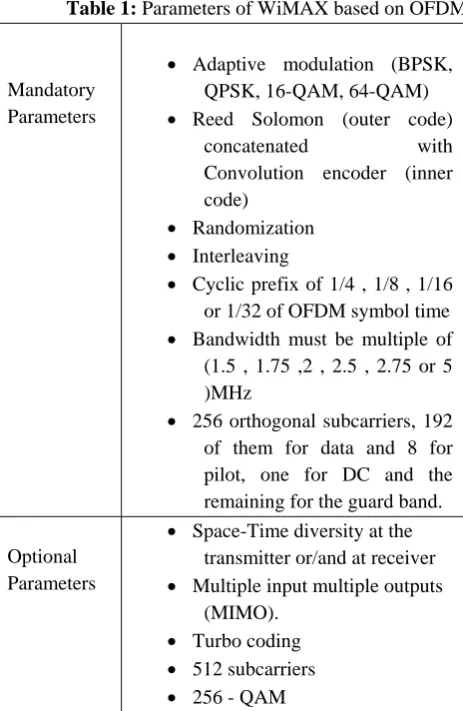
Table 1: Parameters of WiMAX based on OFDM
Mandatory Parameters
Adaptive modulation (BPSK, QPSK, 16-QAM, 64-QAM) Reed Solomon (outer code)
concatenated with Convolution encoder (inner
code)
Randomization Interleaving
Cyclic prefix of 1/4 , 1/8 , 1/16 or 1/32 of OFDM symbol time Bandwidth must be multiple of
(1.5 , 1.75 ,2 , 2.5 , 2.75 or 5 )MHz
256 orthogonal subcarriers, 192 of them for data and 8 for pilot, one for DC and the remaining for the guard band. Optional
Parameters
Space-Time diversity at the transmitter or/and at receiver Multiple input multiple outputs
(MIMO). Turbo coding 512 subcarriers 256 - QAM
It consists of parameters; part of which is mandatory and others are optional. Table 1 shows the main WiMAX parameters [10].
II. SYSTEMMODEL
The block diagram of a WiMAX OFDM-based system consists basically of the transmitter, the receiver and the fading channel between them. The fading channel model will be described in a separate section. The transmitter is composed of the primary blocks, shown in Figure 1. The channel encoder separates or segments the incoming bit stream (the output of the source encoder) into equal length blocks of L binary digits and maps each L- bit message block into an N - bit code word where N >L and the extra N – L check bits provide the required error protection. There are M = 2^L messages and thus 2^L code words of length N bits. The channel decoder maps the received N -bit word to the most likely code word and inversely maps the N -bit code word to the corresponding L -bit message.
During the symbol mapping stage, the sequence of binary bits is converted to a sequence of complex valued symbols [10].
[image:2.595.53.285.429.785.2]In order to overcome the inconvenient requirement for RF radios in both the transmitter and the receiver, OFDM uses a technique called Discrete Fourier Transform (DFT), which leads itself to a highly efficient technique known as the fast Fourier transform (FFT). The FFT and its inverse, the IFFT, can create a multitude of orthogonal subcarriers using a single radio.
Figure 1: Block diagram of MIMO - OFDM transmitter
The cyclic prefix provides a guard interval for all multipaths following the first arrival signal. As a result the time required to observe a useful OFDM symbol is quite up to the guard band interval, allowed.
[image:2.595.294.557.499.603.2]demodulation) is applied to get back to the frequency domain. The output is then serialized. Symbol de-mapping is done to get back the coded bit sequence. Channel decoding, interleaving, Viterbi decoding, de-randomization) is done to get the user bit sequence.
Figure 2: Block diagram of MIMO-OFDM receiver
The de-interleaver performs the inverse operation of the interleaver. The interleaver ensures that the 2 bits, output by the channel coder, are sent on separate carriers that are far apart from one another [10]. This leads to a frequency diversity benefit. Specifically, since each of the 2 bits output from the channel coder is positioned at a very different carrier, each bit experiences a unique gain (a unique fade).
The de-randomizer is used at the receiver to recover the original data again from the randomized data. It has the same construction of the Randomizer, where the data undergoes an XOR operation with the output of Pseudo Random Binary Shift Generator PRPG that has a linear feedback shift register (LFSR) [10].
A Viterbi decoder uses the Viterbi algorithm for decoding a bitstream that has been encoded using Forward error correction based on a Convolutional code. The Viterbi algorithm is a resource-consuming one, but it does the maximum likelihood decoding. It is most often used for decoding convolutional codes with constraint lengths k<=10, but values up to k=15 are used in practice.
III. TRANSMITTEDSIGNALEXPRESSION
If N sub-carriers are used, and each sub-carrier is modulated using M alternative symbols, the OFDM symbol alphabet consists of M N combined symbols.
The low-pass equivalent OFDM signal is expressed as:
(1) Where {xk} are the data symbols, N is the number of
carriers, and T is the OFDM symbol time. The
sub-carrier spacing of 1/T makes them orthogonal over each symbol period; this property is expressed as:
(2) To avoid inter symbol interference in multipath fading channels, a guard interval of length Tg is inserted prior to
the OFDM block. During this interval, a cyclic prefix is transmitted such that the signal in the interval Tg< t < 0 equals the signal in the interval T – Tg < t < T. The OFDM
signal with cyclic prefix is thus:
(3) The low-pass signal above can be either real or complex-valued. Real-valued low-pass equivalent signals are typically transmitted at baseband—wireline applications such as DSL use this approach. For wireless applications, the low-pass signal is typically complex-valued; in which case, the transmitted signal is up-converted to a carrier frequency fc. In general, the transmitted signal can be
represented as:
(4)
IV. SUICHANNELMODELS
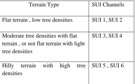
To check the performance of any wireless communication system before is practically built, the system must be tested under real wireless channel scenarios using computer simulation. For this purpose, Stanford University Interim (SUI) channels provide three main terrain types that represent most fading channel characteristics in nature [11].
These types are summarized as: Soft fading (SUI 1, SUI 2)
Table 2: General characteristic in each type
Terrain Type SUI Channels Flat terrain , low tree densities SUI 1, SUI 2 Moderate tree densities with flat
terrain , or not flat terrain with light tree densities
SUI 3, SUI 4
Hilly terrain with high tree densities
SUI 5 , SUI 6
[image:4.595.51.287.353.670.2]As we note, every two channels determine the range of fading characteristic in each terrain type. For example the SUI 1 represents the lowest fading effects in the soft fading region, while the SUI 2 represents the highest fading effects in that region .
Table 3: SUI channel characteristics
Table 4: SUI channel parameters
These channel models are standardized according to the following conditions:
Cell Size: 7Km.
BTS antenna height: 30 m. Receive antenna height: 6m. BTS antenna beamwidth: 1200.
Receive antenna beamwidth: omnidirectional. Polarization: Vertical only.
90% cell coverage with 99.9% reliability at each location covered.
V. SIMULATIONMODEL
In our work, we used the following parameters to
analyze our system: Bandwidth: 5 MHz.
Modulation: 64 QAM and 256 QAM. Guard width ratio (G): 1/4.
Coding rate: 3/4.
Number of subcarriers: 256 and 512. Channels: SUI 1 - SUI 6 compared to
AWGN and Rayleigh.
Reed-Solomon, Convolutional coding at the transmitter & Viterbi decoding at the receiver. Tap power (dB) Spread delay (µ sec) K factor Doppler (Hz) T A P 1 T A P 2 T A P 3 T A P 1 T A P 2 T A P 3 T A P 1 T A P 2 T A P 3 T A P 1 T A P 2 T A P 3 S U I 1
0 15 -20
0 0.4 0.9 4 0 0 0.4 0.3 0
. 5 S U I 2
0 12 -15
0 0.4 1.1 2 0 0 0.2 0.15 0
. 2 5 S U I 3
0 -5 -10
0 0.4 0.9 1 0 0 0.4 0.3 0
. 5 S U I 4
0 -4 - 8
0 1.5 4 0 0 0 0.2 0.15 0
. 2 5 S U I 5
0 -5 -10
0 4 10 0 0 0 2 1.5 2
. 5 S U I 6
0 10 -14
0 14 20 0 0 0 0.4 0.3 0
. 5 SU I1 SUI 2 SUI 3 SUI 4 SUI 5 SUI 6 Spread delay Low Mode-rate High K factor High norma- lized componen t of LOS
Low norm. comp. LOS
Here K= 0 since there is no LOS in these scenarios; merely NLOS (Non Line Of Sight)
Tap Pow-er
Low High Moderate to
high
Dop-pler Shift
Low High Low Hig
h Ter-rain Type Flat terrain , low tree densities , Moderate tree densities with flat terrain , or not flat terrain with light tree densities
0 2 4 6 8 10 12 14 16 18 20 22 24 26 28 30 32 34 36 38 40 42 44 45 10-4
10-3 10-2 10-1 100
SNR (dB)
BER
SUI-1 SUI-2 SUI-3 SUI-4 SUI-5 SUI-6 Theoretical ber AWGN ber
0 2 4 6 8 10 12 14 16 18 20 22 24 26 28 30 32 34 36 38 40 42 10-4
10-3 10-2 10-1 100
SNR (dB)
BE
R
64-QAM(3/4) with 1x1 64-QAM(3/4) with 1x2 64-QAM(3/4) with 1x4 64-QAM(3/4) with 2x2 64-QAM(3/4) with 4x4 Theoretical BER of 64-QAM AWGN BER
Receiver Diversity (1x2 and 1x4). MIMO Diversity (2x2 and 4x4). Variable SNR (0 – 44 dB).
For our simulation, Matlab R2008a version 7.6.0.324 is used. Matlab has many important features that make it one of main important programs in technical computing; especially in signal processing .It provides algorithms and tools for the design and simulation of signal processing systems. Furthermore, it offers design and analysis algorithms for the physical layer of communication systems.
As a result, one can divide the physical layer into a cascade of algorithms. Each algorithm is represented by a MATLAB function that acts on the signal arrays. In addition, one can run the simulation many times and compare the results under a combined plot window.
1. In our simulation we used several built-in functions from the communication toolbox. The following are the description of these functions :
2. The generation of random data (randint): this function generates a random data to represent the real data. 3. Reed Solomon encoding & decoding (rsenc/rsdec):
these function apply the Reed Solomon coding process for the suitable data form.
4. Convolutional encoding and decoding (convenc, vitdec): this function applies the convolution coding to the incoming data.
5. fft/ifft : this function generate the OFDM subcarriers 6. Symbol mapping and modulation : there are function
perform this part such as qammod / qamdemod, modulate.
7. Convolution function(conv) : this function to perform the convolution between the signal and the channel impulse response (CIR)
8. biterr: this function to calculate the number of the error bit
9. Semilog: for plotting the relationship between the BER and SNR.
VI. RESULTSANDDISCUSSION
In this part we introduce the results of simulation of IEEE 802.16d with MIMO and diversity, Our focus, in Figures 4-6 would be for 256-QAM , BW = 5 MHz , G=1/4 under SUI3; an intermediate fading channel. The performance challenges become severe for SUI5 and SUI6.
[image:5.595.311.550.50.226.2]Figure (3) shows the performance of fixed WiMAX system under all SUI channel models when 64-QAM, used as a modulation scheme. SUI 6 offers the worst fading characteristics that require high SNR to achieve a relatively low BER.
Figure 3: BER plots vs. SNR for 64-QAM (3/4) under different SUI channels, BW= 5MHz, G= 1/4. Curves (from left to right): AWGN, Theoretical, SUI 1-6. Figure (4) shows the performance of the fixed WiMAX system when receive diversity and MIMO are used at mandatory 64QAM and 256 OFDM subcarriers. The performance significantly improves with MIMO and diversity. Also if we look carefully, the 1x4 receive diversity and 2x2 MIMO have nearly similar performance under SUI 3 .This leads us to conclude that 2x2 is better than 1x4 ; since 1x4 improves the performance - in terms of BER – while 2x2 satisfies a close performance as in 1x4 and doubles the relative data rate. Specifically, the required SNR to achieve 10-3 BER level under SISO (single-input single-output) WiMAX is 37.5 dB, while for 1x2 diversity; the required SNR is 28 dB at 10-3 BER level. In 1x4 and 2x2, the required SNR is nearly the same and equal 22 dB at 10-3. Finally, the required SNR to achieve 10-3 BER level under 4x4 MIMO is 9 dB. In other words , 1x2 improves 9.5 dB compared to SISO-WiMAX at 10-3
BER level , while 1x4 and 2x2 introduces an improvement of 15.5 dB with respect to SISO at that BER .
Figure 4: BER plots vs SNR for different receiver. Diversity/ MIMO orders for SUI 3, 64-QAM(3/4), BW= 5 MHz, G=1/4 Curves (from left to right): Diversity order 4x4, AWGN, Theoretical, 1x4, 2x2, 1x2 and 1x1 respectively.
0 2 4 6 8 10 12 14 16 18 20 22 24 26 28 30 32 34 36 38 40 42 44 46 10-4
10-3 10-2 10-1 100
SNR (dB)
BER
256-QAM(3/4) with 1x1 256-QAM(3/4) with 1x2 256-QAM(3/4) with 1x4 Theoretical BER of 256-QAM AWGN BER
0 2 4 6 8 10 12 14 16 18 20 22 24 26 28 30 32 34 36 38 40 42 44 46
10-4 10-3 10-2 10-1 100
SNR (dB)
BER
256-QAM(3/4) with 1x1 256-QAM(3/4) with 2x2 256-QAM(3/4) with 4x4 Theoretical BER of 256-QAM AWGN BER
0 2 4 6 8 10 12 14 16 18 20 22 24 26 28 30 32 34 36 38 40 42 44 46
10-4 10-3 10-2 10-1 100
SNR(dB)
ber
64-QAM(3/4) with 256 subcarriers
256-QAM(3/4) with 256 subcarriers
64-QAM(3/4) with 512 subcarriers
256-QAM(3/4) with 512 subcarriers
[image:6.595.54.285.265.457.2]curves are compared to a theoretical Rayleigh fading channel, as well as to AWGN channel. It is noticed that BER decreases when the diversity order increases, the reason for this; that the receiver diversity uses multiple antenna at the receiver and this enables the receiver to receive different copies of the same signal, so the probability for all copies under the threshold of detection would be very small. For example, if we assume that the probability of the signal to be under the threshold level is P, then the probability for n different copies of the same signal to reach the receiver under that threshold will be Pn, so the probability is decreased to the nth power of P. At BER = 10-2, the relative improvement in required SNR for 1x2 receive diversity, over no diversity, is 11 dB and for 1x4 receive diversity 17 dB, respectively.
[image:6.595.311.546.469.661.2]Figure 5: BER plots vs. SNR for different receiver diversity orders under SUI 3, 256-QAM(3/4) , BW = 5 MHz , G= 1/4. Curves (from left to right): AWGN, Theoretical, Diversity order 1x4, 1x2, 1x1 respectively.
Figure 6: BER plots vs. SNR for different MIMO orders under SUI 3, 256-QAM(3/4), BW = 5 MHz, G= 1/4. Curves (from left to right): MIMO order 4x4, AWGN, Theoretical, 2x2 and 1x1 respectively.
Figure (6) shows BER versus SNR for different MIMO orders under SUI3 and 256QAM modulation. We notice that the 4x4 MIMO has, as expected, the best performance. For example, if we consider BER of 10-3, we observe that the required SNR to achieve this BER when no MIMO is used would be 35 dB, but under 2x2 MIMO, it would be 27 dB, while for 4x4 MIMO it will be 16 dB. So the 2x2 gains an improvement of 8 dB than when no MIM O is used, while 4x4 gains an improvement of 19 dB than when no MIMO is used. At BER= 10-2, the relative improvement in required SNR for 2x2 MIMO, over no diversity, is 18 dB and for 4x4 MIMO 28 dB, respectively.
In Figure 7, we note the performance of the WiMAX decreases when the number of subcarriers increases while the bandwidth remains constant. For example, the required SNR to achieve BER of 10-2 for 64-QAM and 256 subcarriers is 32 dB while under 512 subcarriers it will be 35 dB; a 3 dB deterioration in performance. For 256-QAM and 256 subcarriers SNR is 40 dB while under 512 subcarriers it is 42 dB; a roughly 2 dB deterioration in performance.
[image:6.595.54.284.534.714.2]
As expected, when the number of subcarriers increases at fixed BW, then the spacing between the carriers decreases. This leads to cause interference between the adjacent subcarriers, which in turn leads to a decrease in performance. In general, however, 256-QAM is a high order modulation (high data rate) that requires good conditions regardless the number of subcarriers.
Figure 7: BER plots vs. SNR for different numbers of Subcarriers under SUI 3, 64-QAM and 256-QAM (3/4), BW = 5 MHz, G= 1/4.
VII. CONCLUSION
The following improvements, achieved in the results of this work are hereby summarized:
1. Using 2x2 MIMO for 256 QAM modulations under SUI 3 gains a percentage improvement of approximately 42.8% over SISO to achieve the same BER.
2. Using 4x4 MIMO for 256 QAM modulations under SUI 3 gains a percentage improvement of approximately 69% over SISO to achieve the same BER.
3. Using 4x4 MIMO for 256 QAM modulations under SUI 3 gives a BER-SNR performance better than AWGN BER (non-fading).
4. When the receiver diversity of order 1x2 is used a percentage improvement of approximately 26.2% over SISO is realized when 256 QAM modulation scheme is used under SUI 3.
5. When the receiver diversity of order 1x4 is used a percentage improvement of approximately 40.47% over SISO is realized when 256 QAM modulation scheme is used under SUI 3.
6. It is better to use 2x2 MIMO than 1x4 receives diversity since both give the same performance under same environmental conditions while 2x2 MIMO doubles the data rate and relatively improves BER. 7. When 256 QAM modulations are used under SUI 3
using 512 subcarriers, an SNR of 42 dB is required to achieve a 10-2 BER level. Therefore a MIMO system must be used to enhance the performance.
References
[1] WiMAX Forum, Mobile WiMAX – Part I: A Technical Overview and Performance Evaluation, February 21, 2006.
[2] Jeffrey G. Andrews, Arunabha Ghosh, Rias Muhamed,"Fundamentals of WiMAX: Understanding Broadband Wireless Networking", Prentice Hall, USA, Feb. 2007.
[3] Shah P. , Mondal, K. , "Fixed WiMAX Downlink Spectral Efficiency and Throughput Measurements under Channel Impairments" Computer Science and Information Engineering, 2009 WRI World Congress , Volume: 1 , 2009 , Page(s): 394 - 398 .
[4] C. Singh Bikash, M. Mahbubur Rahman, Tapan K. Godder, Abu L., Bashar Md. R., "Channel based Simulation and analysis of IEEE802.16 (WiMAX) — 2004/WMAN-OFDM physical layer for BWA to support Telemedicine" , Complex Medical Engineering (CME), IEEE/ICME International Conference , 2010 , Page(s): 231 – 236.
[5] M. Djurdjevic , B. Modlic, G. Sisul, M. Cvitkovic," Fixed WiMAX downlink simulation model”, International Symposium, ELMAR, 2009, pp. 237 - 240.
[6] Zamiri-Jafarian H., Rajabzadeh M., "A Polynomial Matrix SVD Approach for Time Domain Broadband Beamforming in MIMO-OFDM Systems ", Vehicular Technology Conference, 2008. VTC Spring 2008. IEEE, 2008, pp. 802 - 806.
[7] Gutierrez I., Bader F., Mourad A. , “Joint Transmit Antenna and space-time coding selection for WiMAX MIMO systems”, Personal, Indoor and Mobile Radio Communications, 2009 IEEE 20th International Symposium, 2009, pp. 3138 - 3143.
[8] Kobeissi, R., Sezginer, S., Buda, F., "Downlink Performance Analysis of Full-Rate STCs in 2x2 MIMO WiMAX Systems" Vehicular
Technology Conference, VTC Spring 2009. IEEE 69th, 2009, pp. 1 - 5.
[9] “IEEE 802.16-2004 OFDM PHY Link, Including Space-Time Block Coding- Demo Baseband Model”, Communications Toolbox, MATLAB Release R2008a, The Math Works, 2008.
[10] Air interface for fixed broadband wireless access systems, IEEE STD 802.16, October 2004, pp. 1-857.