Preparation and Mechanical Optimization of
Composite Pipes
B.Sandeep1, CH. Jeevan Reddy2, Santosh Ghorpade3, Harish R4 1, 2, 3, 4
Asst.Prof, Department of Mechanical Engineering, JITS. Narsampet, TS, INDIA
Abstract: Composite materials reinforced with synthetic fibers such as glass, carbon, and aramid provide a Advantages of high stiffness and strength to weight ratio as compared to conventional construction materials, i.e. wood, concrete, and steel. But replace of synthetic fiber of composite Material to natural fibers like Kenaf, cotton, jute, etc and improve the properties of natural and compare to other synthetic fiber as well as now used material and prepared for Kenaf, cotton and jute fiber and e-glass fiber compare the properties as tensile test and water absorption and pressure test and manufacturing of composite pipes of Kenaf ,jute and cotton and composite pipe of E-Glass are finding the best properties of composite material will be compare, check and also find out the result in ANSYS(Work Bench) and develop the real applications composite pipes and check the all failure condition of composite pipes due to ASTM specification to PVC pipes compare with composite pipes and their improve the properties and design model with help up mechanical tool and design calculation of a different type of composite pipes and prove the best model of natural composite model (pipe) .
Keywords: kenaf, jute, cotton, E-Glass
I. INTRODUCTION
Composite is defined as the combination of any two or more materials i.e. metal, polymer and ceramics. The interest in natural fiber-reinforced polymer composite materials/Bio composites is rapidly growing both in terms of their industrial applications and fundamental research. They are renewable, cheap, completely or partially recyclable, and biodegradable. Plants such as flax, cotton, hemp, jute, sisal, century, Kenaf, pineapple, ramie, bamboo, banana, etc., as well as wood, used from time immemorial as a source of lignocelluloses fibers, are more and more often applied as the reinforcement of composites.
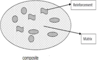
[image:1.612.230.386.504.600.2]Composite materials are made from two or more constituents materials with significantly different physical or chemical properties which remain separate and distinct on a macroscopic level within the finished structure. Composites are made up of individual materials referred to as constituent materials. There are two categories of constituent materials referred: Matrix and reinforcement. At least one portion of the each type is required. The matrix materials surround and support the reinforcement materials by maintaining their relative positions. The reinforcement impacts their special mechanical and physical properties to enhance the matrix properties.
Fig 1: Structure of Composite
II. PREPARATION OF COMPOSITE PIPES
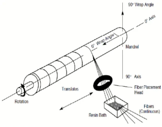
Fig 2: Filament Winding Process
Resin can be applied by resin or spray, though developments in Resin technology and mandrel equipment have combined to markedly increase the use of resin bath application methods. Whichever application method is chosen, it is important to use a Resin from the Cryptic range, specially formulated with the correct theology for that method.
Fig 3: Preparation of composite pipes
For optimum performance, it is important to control the Resin thickness to 0.4mm - 0.5mm and as a guide, 450g-600g/m2 of Resin
mixture will give the required thickness. If the Resin is too thin it may not cure fully and the pattern of the reinforcing fibre may show through from the backing composite.
[image:2.612.113.503.364.514.2]
Thin Resin are also prone to solvent attack from the resin used in the backing composite pipes and this can result in Resin wrinkling. If the Resin is too thick, it may crack or craze and will be more sensitive to impact damage, particularly from the reverse side of the pipe.
A Resin of uneven thickness will cure at different rates over its surface. This causes stresses to be set up in the resin which may lead to crazing or, in the case of,resin transfer approaches methods.
[image:3.612.179.404.145.341.2]Fig 5: compression moulding on pipes
The reinforcement will then conform readily to the contours of the mould. Once the first layer of mat is fully impregnated, further resin can be added, if necessary, before applying subsequent layers of reinforcement. It is important that the first layer is as free of air bubbles as possible, as any air trapped immediately behind the Resin could lead to blistering, should the moulding be exposed to heat or water during its working life. Impregnation of the reinforcement can be carried out using a brush ring, or a mohair or polyester roller.
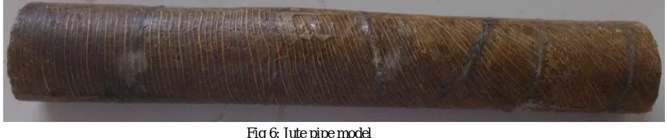
As per ASTM schedule 40D standard pipe specimens of same thickness are cut from the same size composite pipe using compressive moulding and filament winding process to maintain good surface finish as shown in below .
Fig 6: Jute pipe model
III. MODELLING IN ANSYS (WORK BENCH)
The finite element simulation was done by FEA/FEM package known as ANSYS. The FEA- software package offerings include time-tested, industry-leading applications for structural, thermal, mechanical, computational fluid dynamics, and electromagnetic analyses, as well as solutions for transient impact analysis. ANSYS software solves for the combined effects of multiple forces, accurately modeling combined behaviors resulting from "multiphysics" interactions.
This is used to perform the modeling of the ASTM stranded specimen and find the result of stress and strain with relevant mode shapes. This is used to simulate both the linear & nonlinear effects of structural models in a static or dynamic environment also includes the ANSYS WORKBENCH for building and controlling user-defined parametric and customized models.
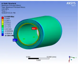
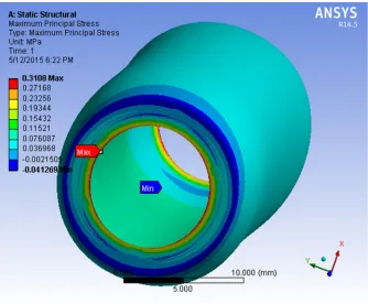
[image:3.612.85.562.459.558.2]A. Stress, Strain and Total Deformation Models of Composite Pipes 1) Maximum principal stress for Kenaf composite pipe model
Fig 7 Maximum principal stress for Kenaf composite pipe model
Maximum principal stress for Kenaf composite pipe model is 0.41669 N/mm2
2) Maximum Principal Elastic Strain for Kenaf Composite Pipe Model
[image:4.612.135.483.439.714.2]Maximum Principal Elastic Strain Kenaf is 1.0023e5 3) Total Deformation for Kenaf Composite Pipe Model
Fig 9. Total Deformation for Kenaf composite pipe model
Total Deformation for Kenaf composite pipe model is 5.013 mm
4) Maximum Principal Stress for Jute Composite Pipe Model
Fig 10 Maximum principal stress for jute composite pipe model
[image:5.612.139.473.407.683.2]5) Maximum Principal Elastic Strain for Jute Composite Pipe Model
Fig 11. Maximum principal strain for jute composite pipe model
Maximum Principal Elastic Strain for jute composite pipe model is 48383
[image:6.612.177.438.318.499.2]6) Total Deformation for Jute Composite Pipe Model
Fig 12. Total Deformation for jute composite pipe model
Total Deformation for jute composite pipe model is 96777 mm
[image:6.612.102.460.563.719.2]Maximum Principal Stress for cotton pipe Model is 0.21287 N/mm2.
[image:7.612.186.429.114.271.2]8) Maximum Principal Elastic Strain for Cotton Pipe Model
Fig 14. Maximum principal strain for cotton composite pipe model
Maximum Principal Elastic Strain for cotton pipe Model is 26285. Maximum Principal Elastic Strain for cotton pipe Model is 26285.
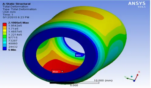
9) Total Deformation for Cotton Pipe Model
Fig 15. Total Deformation for cotton composite pipe model
Total Deformation for cotton pipe Model is 2.1985e5 mm.
[image:7.612.183.432.353.499.2]10) Maximum Principal Stress for E-Glass Pipe Model
Maximum Principal Stress for E-Glass pipe Model is 0.22339 N/mm
[image:8.612.166.443.113.276.2]11) Maximum Principal Elastic Strain for E-Glass Pipe Model
Fig 17. Maximum principal strain for cotton E-Glass pipe model
Maximum Principal Elastic Strain for E-Glass pipe model is 105.49
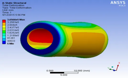
3.1.12 Total Deformation for E-Glass pipe model
[image:8.612.183.451.344.508.2]
Fig 18. Total Deformation for E-Glass pipe model
Total Deformation for E-Glass pipe model 3.6566e5 mm
IV. ANSYS (WORK BENCH) STRESS-STRAIN RESULTS
Jute
σ €
0.310 4838
0.271 4295
0.232 3752
0.193 3709
0.154 2666
0.115 2123
0.076 1580
Kenaf
σ €
4.166 100230
3.559 97910
2.951 79350
2.343 68908
1.731 58460
1.112 48020
[image:8.612.112.538.561.713.2]Table 2. stress-strain result values for cotton,E-Glass
A. Analytical stress –strain curves
Fig 19. stress –strain curves
From above graph it shows that stress-strain values for kenaf, jute, cotton, and E-Glass among all these four materials kenaf fiber gives better stress-strain results as compare with other composite materials
V. CONCLUSION
In the present work, one artificial and three natural fibers are used. The materials selected were fully characterized in terms of their mechanical properties. The data obtained on the single lamina prepared with that natural fibers (i.e Kenaf fiber) has good properties, when compared to the other fibers (Jute, Cotton and E-glass). Experiments were conducted on the prototype model by simulating the real working conditions of Pressure test, tensile test & Water absorption test confirmed that kenaf Fiber only can withstand the real working conditions. Stress-strain and deformation results are obtained by mechanical tool i.e ANSYS WORK BENCH. Which are correlated with the experimental results.
REFERENCES
[1] H ku, H.wang, N.pattarachaiya koop and M.Trada, A Review on the Tensile properties of Natural Fiber Reinforced Polymer Composites,2001,1-51pp
[2] P.V. Josepha, Marcelo S. Rabellob, L.H.C. Mattosoc, Kuruvilla Josepha, Sabu Thomasd: The influence of various ageing conditions like water and UV
radiation on the mechanical properties of sisal/PP composites, New Delhi 1989, 1-78pp.
[3] scott w.beckwith Natural fiber reinforcement materials, lower cost technology for composite applications, November/December 2003,1-16pp.
[4] X.Y Liu,G.C.Dai. Surface modification and micro mechanical properties of jute fiber mat reinforced PP composites received in march,2007,vol1, pp 299-307
[5] Nevin Gamze karsli ,ayse aytac effects of maleated pp on the morphology, thermal and mechanical properties of short fiber reinforced pp composites, material
and design32(2011),pp 4069-4073
[6] Maria wcadyka-przybylak Krzysztof buznow, natural fibers reinforced polymer composites,c.z.institute of natural fiber and medical plants
Poznan,Poland,1997,1-39pp.
[7] K. Kishore Kumar, Dr. k. Raja Narender Reddy and Dr. K. Nageswar Rao, Evaluation of Visco elastic properties of some Malaceave fiber reinforced
composites, International journal of applied engineering research, ISSSN 0973-4562,vol7 no11(2012).
[8] Maya Jacob John, Rajesh D. Anandjiwala, Chemical modification of flax reinforced polypropylene composites, Composites: Part A 40 (2009), pp 442 – 448.
[9] V. Arun, S. Basavarajappa, B.S. Sherigara, Damage characterisation of glasstextile fabric polymer hybrid composites in sea water environment. Materials and
Design 31 (2010), pp 930 – 939.
[10] Craig Clemons, Anand R. Sanadi, Instrumented Impact Testing of Kenaf Fiber Reinforced Polypropylene Composites: Effects of Temperature and
Composition. Journal of Reinforced Plastics and Composites, Vol. 26, No. 15/2007, pp 1587–1602.
[11] Yi Zou, Shah Huda, Yiqi Yang, Lightweight composites from long wheat straw and polypropylene web. Bioresource Technology 101 (2010), pp 2026–2033.
st re ss strain E-Glass cotton jute kenaf E-Glass σ €
0.212 105.49
0.186 94.353
0.159 83.216
0.132 72.079
0.105 60.941
0.078 49.804
0.051 38.667
cotton
σ €
0.223 26285
0.195 23536
0.167 20787
0.140 18039
0.112 15290
0.08 12541
[image:9.612.210.440.245.380.2]