Comparative Study of Settlement Reduction of
Rigid Raft through Granular Pile
Prof. Jitendra Kumar Sharma1, Raksha Rani Sanadhya2
1
Department of Civil Engineering, Rajasthan Technical University, Kota, Rajasthan, India 2
Research Scholar, Department of Civil Engineering, Rajasthan Technical University, Kota, Rajasthan, India
Abstract: Granular piles are a cost-effective technique of ground improvement which increases the load carrying capacity, reduces the settlement of foundations built on the reinforced ground and also a good alternative option of concrete pile. Reinforcement of ground becomes a necessity in many situations, where the soil is extremely weak or soft. The columns of granular material create a composite ground of reduces compressibility and increases shear strength than that of native soil.Piles under the raft are designed to decreases the settlements and differential settlement of the soil. Raft, piles and soil are three components of piled-raft system through which the loads transfer to the subsoil.The present analysis is done to the study the response of a floating granular piled raft based on the elastic continuum approach.
Mathematical study is carried out for the comparative analysis of settlement of granular piled raft to rigid raft only and granular pile alone with variation of comparative stiffness of GP, comparative size of raft and relative length of floating granular pile. The overall response of a granular pile with the rigid raft on top is evaluated in terms ofsettlement influence factor for viz. granular piled raft, rigid raft only, and pile alone. On the basis of findings design charts are prepared to facilitate the design procedure.
Keywords: Granular piled raft, interfacial shear stress, comparative stiffness of granular pile, comparative size of raft, relative length of floating granular pile
I. INTRODUCTION
Use of granular piles (GP) /stone columns/sand compaction piles is considered as one of the most flexible and cost-effective alternatives compared to other methods such as preloading, removal and replacement, thermal stabilization, dynamic compaction, ground freezing, etc. Granular piles are made of compacted sand or gravel installed in soft ground by full displacement methods.Raft foundations are often preferred for high rise buildings constructed on soft soil for distribution of load on a larger area. Piles beneath raft are designed to reduce the settlements and unequaldisplacement of the ground. Raft, piles and soil are three components of piled-raft system through which the loads transfer to the subsoil.
Analysis of a rigid raft over an incompressible pile was presented by Poulos10. Butterfield and Banerjee1 analyzed the pile group-pile cap interaction for the stiffness range of concrete and steel group-piles. Lee and Pande6 presented an axi-symmetric model to study the performance of circular footing overlying stone column improved ground. Canetta and Nova11 bring out a method of analysis of ground enhanced by columnar inclusions. The response of piled raft foundation on soft soil strengthened by short granular piles made of flexible materials was investigated by Liang et. al7. Madhav et al.8 bring out the settlement analysis of a granular pile considering non-homogeneities in the deformation modulus as well as granular pile material.
Grover et. al4 evaluated the vertical displacements of stiffened granular piles depends on the elastic continuum approach and find that with the rise in stiffness of GP, the displacement of a floating GP reduces. The effect of pile length and alignment on attained final load was investigated by Elwakil and Azzam3. El-garhy and Elsawy2 presented a method to investigate strip footing founded on a granular layer over expensive soil stabilized by floating granular or piles resting on bearing stratum. Gupta and Sharma5 conduct a study of a non-homogeneous GP with non-linear behaviour of modulus of elasticity for displacement analysis.
II. ANALYSIS OF GRANULAR PILED RAFT
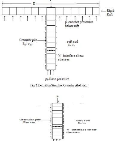
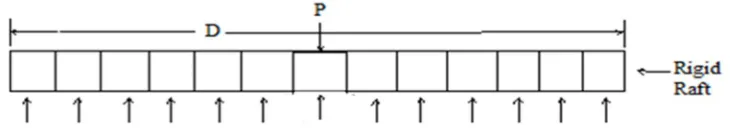
Fig. 1 shows a granular piled raft foundation carrying a load, P. The raft is rigid and of diameter, D. The granular pile shown in Fig. 2 is compressible with a constant of deformation or elasticity, Egp , Poisson’s ratio, νgp , diameter, d (=2a), and length, L . The surrounding soft soil is characterized by it’s the modulus of deformation, Es, and Poisson’s ratio, νs. The present analysis uses the continuum approach to determine the stress systems, shear stresses along with the pile, τ and base pressure on the base of GP, pb,
[image:2.612.111.505.220.693.2]along with the soil-granular pile interface and raft stresses, pr, at the raft – soil interface, which accomplish the similarity of displacements along the interfaces depicts in Fig. 3. For no slip at GP-soil interface, the GP and the raft displacements are equated to the soil settlement at the corresponding nodes. The stresses and the soil displacements for GP and raft are evaluated depends on the interactions of raft on raft, raft on GP, GP on GP and GP on raft. The essential steps of the analysis are the evaluation of (a) Soil displacements, (b) Granular pile displacement (c) raft displacements and (d) compatibility displacements.
[image:2.612.183.432.538.710.2]Fig. 1 Definition Sketch of Granular piled Raft
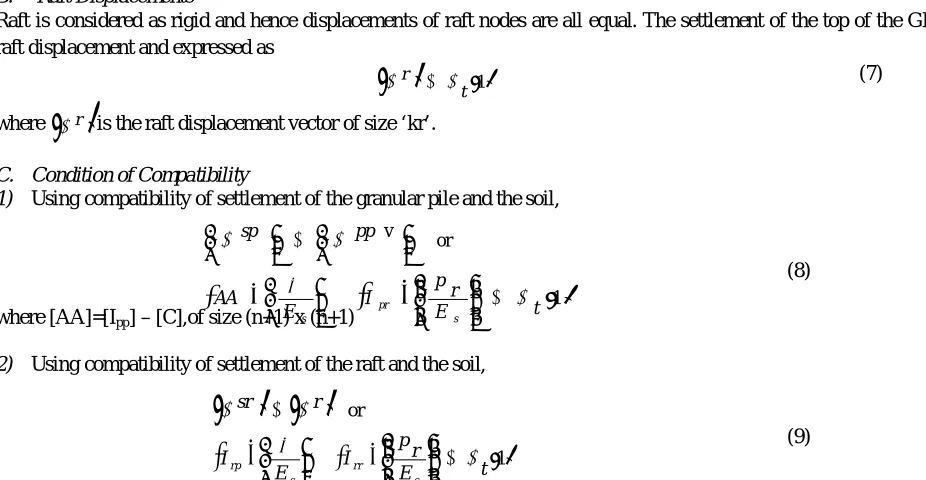
Fig. 3 Definition Sketch Rigid Raft
III. SOIL DISPLACEMENTS
Soil displacements along with GP-soil interface and along the raft-soft ground interface are evaluated at the mid-points on the side of each element by integrating Mindlin (1936) and Boussinesq’s expressions correspondingly. The GP is divided in to ‘n’ elements
of length, Δ L (= L / n ). Displacements along GP-soil interface are evaluated at the mid-point on the side of each elements and at the centre of the base by the integration of Mindlin & Boussinesq’s expressions depends on the effect of the elemental stresses of GP and the raft stresses correspondingly in matrix form following Sharma and Madhav (1999)
(1)
where {Ssp} and {rsp} are vertical and standardize vertical soil settlement vectors, [Ipp]=(n+1)x(n+1) of the displacement factor calculated by integrating Mindlin’s equation [Ipr]= (n+1)xkr, of the displacement factor calculated by integrating Boussinesq’s equation {τ}and {pr} – column matrix , {n+1}and {kr} correspondingly.
(2)
where{Ssr} and {sr} are vertical and standardize vertical soil settlement vector, [Irp]= kr(n+1), whose displacement factor are evaluated by integrating Mindlin’s [Irr] = (kr x kr) of the displacement factor evaluated by integrating Boussinesq’s equation {} and {pr} - column matrix of size {n+1} and {kr} correspondingly
A. Pile Settlement
Displacements of node of granular pile are calculated depends on a stress-strain relationship
gp E
v v
(3)
Where v, are the direct/direct strains, and v is the direct/direct stress on the element and Egp is the elasticity modulus of the granular pile.
1) Direct & Shear Stresses Relationship
A
v (4)
where {} and {v} are consecutively columns matrix of shear and direct stresses on the pile nodes, size of both vectors is (n+1). [A] is a matrix of (n+1) x(n+1) size is formulated.
2) GP Displacements
The vertical displacements of granular pile is
s E B t
ppv 1 v
(5)
where [B] is matrix of size (n+1)(n+1)
By replacing the direct stresses by shear stresses using (Eq. 4), the settlement of granular pile nodes in form of shear stresses is
s E C t ppv 1 (6)
where [C] =(n+1)x (n+1) matrix.
B. Raft Displacements
Raft is considered as rigid and hence displacements of raft nodes are all equal. The settlement of the top of the GP (t) is equal to raft displacement and expressed as
(7)
where
r is the raft displacement vector of size ‘kr’.C. Condition of Compatibility
1) Using compatibility of settlement of the granular pile and the soil,
(8)
where [AA]=[Ipp] – [C],of size (n+1) x (n+1)
2) Using compatibility of settlement of the raft and the soil,
(9)
By solving the equations (8) & (9) standardize raft stresses and normalised interfacial shear stresses are evaluated. Further the settlement at the top granular piled Raft foundation, granular pile alone and rigid raft are evaluated as
(10)
where Ip, is settlement influence factor.
Present study deals with the analysis of granular pile with rigid raft based on the elastic continuum approach. The objectives of this study to include the comparative settlement study of granular piled raft to settlement of rigid raft only and granular pile alone. Response of granular piled raft is presented in terms of following factors
a) Settlement factor (SF), α = Settlement of granular piled raft/ settlement of pile alone. b) Settlement ratio (SR), γ = Settlement of granular piled raft/ settlement of rigid raft.
IV. RESULTS AND DISCUSSION
Following variations of non-dimensional variable incorporated in the study are, comparative length of GP, L/d = 10-40, relative or comparative stiffness, Kgp of GP = 10-1000, comparative size of raft, D/d = 2-10, Poisson’s ratio of soil, νs = 0.3-0.5, and Poisson’s
[image:4.612.43.506.164.404.2]ratio of GP, νgp=0.3-0.5.
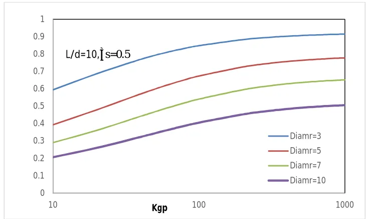
Fig. 4 represents the variation of SF, α, with the comparative stiffness of granular pile, Kgp along with influence of comparative size of raft, D/d for L/d = 10, υs =0.5. With the rise of comparative stiffness of GP, Kgp, the SF increases. Settlement of pile alone decreases more as compare to settlement of piled raft with the increase in the comparative stiffness of granular pile, Kgp. It can be well seen that the SF reduces with the increase in the comparative size of raft, D/d. For L/d = 10, υs =0.5, Kgp = 10 and D/d= 3, 5, 7and 10 the values of SF are 0.59, 0.39, 0.28, and 0.20 correspondingly. The percentage decrease in SF is 66 for an increase in raft size, D/d, from 3 to10.
1t
r
1or v t E r p I E AA pp sp s pr s
1Fig. 4 Plot of settlement factor, α, with the comparative stiffness of GP, Kgp – effect of comparative size of raft, D/d on granular pile raft foundation (L/d=10, υs=0.5)
Fig. 5 depicts the variation of SF, α, with the comparative stiffness of granular pile, Kgp along with effect of comparative size of raft,
D/d, for L/d = 20, υs =0.5. The SF increases with the rise of comparative stiffness of GP, Kgp. It may be noted that the SF reduces with the increase in the comparative size of raft, D/d this is because with the size of raft increases the settlement of pile raft reduces therefore SF is reduced. For L/d = 20, υs =0.5, Kgp = 100 and D/d= 3, 5, 7and 10 the values of SF are 0.85, 0.69, 0.54, and 0.44 correspondingly. The percentage decrease in SF is 48 for an increase in raft size, D/d, from 3 to10.
Fig. 4 Plot of settlement factor, α, with the comparative stiffness of GP, Kgp – effect of comparative size of raft, D/d on granular
pile raft foundation (L/d=20, υs=0.5)
The variation of SF α, with the comparative stiffness of granular pile, Kgp along with effect of comparative size of raft, D/d, for L/d
= 20, υs =0.5 shown in Fig. 6. It can be well seen that the SF reduces with the increase in the comparative size of raft, D/d. The SF, α rises with the rise of comparative stiffness of GP, Kgp and the difference between the curves is reduced with the increase of comparative stiffness of GP, Kgp. It implies that as the stiffness of pile increases the settlement is also reduces. For L/d = 40, υs =0.5, Kgp = 1000 and D/d= 3, 5, 7and 10 the values of SF are 0.96, 0.90, 0.83, and 0.73 correspondingly. The percentage decrease in SF is 21 for an increase in raft size, D/d, from 3 to10.
0 0.1 0.2 0.3 0.4 0.5 0.6 0.7 0.8 0.9 1
10 100 1000
α
Kgp
Diamr=3 Diamr=5 Diamr=7 Diamr=10
L/d=10,υs=0.5
0.1 0.2 0.3 0.4 0.5 0.6 0.7 0.8 0.9 1
10 100 1000
α
Kgp
Diamr=3 Diamr=5 Diamr=7 Diamr=10
Fig. 6 Plot of settlement factor, α, with the comparative stiffness of GP, Kgp – effect of comparative size of raft, D/d on granular
pile raft foundation (L/d=40, υs=0.5)
Variation of settlement ratio, γ with comparative stiffness of granular pile, Kgp, with the influence of comparative size of raft, D/d on a granular pile raft for L/d=10 and υs=0.5 depict in Fig.7. The settlement ratio decreases with increases in comparative stiffness of granular pile, Kgp. It can also be noted that settlement ratio increases with the increase in comparative size of raft, D/d. For L/d =
[image:6.612.128.485.355.493.2]10, υs =0.5, Kgp = 10 and D/d= 3, 5, 7and 10 the values of SF are 0.84, 0.93, 0.96 and 0.98 correspondingly the percentage increase in settlement ratio are 10, 14 and 16 respectively with reference to D/d=3. As the size of raft (D/d=10) increases the settlement ratio is reaches towards 1for lesser comparative stiffness (Kgp=10) of granular pile.
Fig. 7 Plot of settlement ratio, γ, with the comparative stiffness of GP, Kgp – effect of comparative size of raft, D/d, on granular piled raft foundation (L/d=10, υs=0.5)
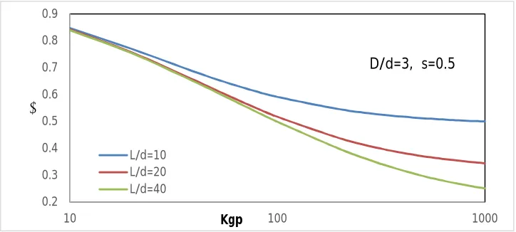
Fig. 8 Plot of settlement ratio, γ, with the comparative stiffness of GP, Kgp – effect of comparative length of granular pile, L/d, on granular piled raft foundation (D/d=3, υs=0.5)
0 0.2 0.4 0.6 0.8 1 1.2
10 100 1000
α
Kgp
Diamr=3 Diamr=5 Diamr=7
L/d=40,υs=0.5
0.4 0.5 0.6 0.7 0.8 0.9 1
10 100 1000
γ
Kgp
Diamr=3 Diamr=5 Diamr=7 Diamr=10
L/d=10,υs=0.5
0.2 0.3 0.4 0.5 0.6 0.7 0.8 0.9
10 100 1000
γ
Kgp
L/d=10 L/d=20 L/d=40
[image:6.612.125.487.532.695.2]Fig.7 depicts variation of settlement ratio, γ with comparative stiffness of granular pile, Kgp, with the influence of comparative length of GP, L/d on a granular pile raft for L/d=10 and υs=0.5. The settlement ratio decreases with increases in comparative stiffness of granular pile, Kgp. It can also be noted that settlement ratio decreases with the increase in comparative length of pile, L/d as it is well noted with the increase in the length of pile the settlement of piled raft is reduces and the settlement of raft is un affected
with the length of pile therefore the settlement ratio decrease. For D/d = 3, υs =0.5, Kgp = 100 and L/d= 10, 20 and 40 the values of settlement ratio are 0.59, 0.51 and 0.49 correspondingly the percentage decrease in settlement ratio are 13 and 16 percent respectively with reference to L/d=10.
V. CONCLUSION
Depends onelastic continuum approach a pile settlement matrix is formulated in the current study. Following are the outcome of this study.
A. Regarding the rise of relative or comparative stiffness of GP, Kgp, settlement factor, α increases.
B. The settlement factor, α reduces with the increase of comparative size of raft, D/d and comparative size of granular pile, L/d. C. For L/d = 10, υs =0.5, Kgp = 10 the percentage decrease in settlement factor is 66 for an increase in comparative size of raft,
D/d, from 3 to10.
D. The settlement ratio, γ reduces with the increase of comparative size of granular pile, L/d and settlement ratio, γ increases with
comparative size of raft, D/d.
E. The settlement ratio, γ reduces with the increase of comparative length of granular pile, L/d. the percentage reduction in the settlement ratio is 16 with the increase in comparative length from L/d=10 to 40.
REFERENCES
[1] Butterfield, R. and Banerjee, P.K., (1971) “The problem of pile group-pile cap interaction”, Geotech, 21 (2), 135-142.
[2] El‑Garhy, and Elsawy, (2017) “Effect of different parameters on the behaviour of strip footing resting on weak soil improved by granular piles”, Int.Journal of Geo-Engineering, 8:4, DOI: 10.1186/s40703-017-0042-2
[3] Elwakil, A.Z., and Azzam, W.R., (2016) “Experimental and Numerical study of piled raft system”, Alexandria Engineering Journal, 55, 547-560. [4] Grover, K.S., Sharma, J.K., and Madhav, M.R., (2015) “Settlement analysis of single granular pile with stiffened top” Int J Sci. Eng. Res.6 (6), 61–75. [5] Gupta, P. and Sharma, J.K., (2018) “Effect of Nonlinear Non-homogeneity of Floating Granular Pile and Soil on Settlement”, Journal of The Institution of
Engineers (India), 1-11, series A
[6] Lee J. S., and Pande G. N.,(1998) “Analysis of Stone-Column Reinforced Foundations”, Int. J. Numer. Anal. Meth. Geomech., 22, 1001—1020 (1998) [7] Liang, F.Y., Chen, L.Z., and Shi, X.G., (2003) “Numerical analysis of composite piled raft with cushion subjected to vertical load” computers and geotechnics
30, 443-453.
[8] Madhav, M.R., Sharma, J.K. and Chandra, S. (2006), Analysis and settlement of a non-homogeneous granular pile, Indian Geotechnical Journal, 36(3), 249-271.
[9] Mindlin, R.D., (1936) “Force at a point in the interior of a semi-infinite solid”, Physics, 7, 195-202.
[10] Poulos, H.G.,(1968) “The influence of rigid pile cap on the settlement behaviour of an directly loaded pile”, C.E. Trans. Inst. Engrs., Australia, CE10 (2),206-208.
[11] Canetta G, Nova R. (1989) “A numerical method for the analysis of ground improved by columnar inclusions” Computers and Geotechnics, 7, 99-14.