Using Directional Antennas for
Medium Access Control in Ad Hoc Networks
∗Romit Roy Choudhury,
+Xue Yang,
+Ram Ramanathan
∗and Nitin H. Vaidya
++
Dept. of Electrical and Computer Engineering, and Coordinated Science Laboratory
University of Illinois at Urbana-Champaign
{croy, xueyang, nhv}@crhc.uiuc.edu ∗
Internetwork Research Department
BBN Technologies (A Part of Verizon)
ramanath@bbn.com
ABSTRACT
Previous research in wireless ad hoc networks typically as-sumes the use of omnidirectional antennas at all nodes. With omnidirectional antennas, while two nodes are communicat-ing uscommunicat-ing a given channel, MAC protocols such as IEEE 802.11 require all other nodes in the vicinity to stay silent. With directional antennas, two pairs of nodes located in each other’s vicinity may potentially communicate simulta-neously, depending on the directions of transmission. This can increase spatial reuse of the wireless channel. In addi-tion, the higher gain of directional antennas allows a node to communicate with other nodes located far away, implying that messages could be delivered to the destination in fewer hops. In this paper, we propose a MAC protocol that ex-ploits the characteristics of directional antennas. Our design focuses on using multi-hop RTSs to establish links between distant nodes, and then transmit CTS, DATA and ACK over a single hop. Results show that our directional MAC proto-col can perform better than IEEE 802.11, although we find that the performance is dependent on the topology configu-ration and the flow patterns in the system.
Categories and Subject Descriptors
C.2.1 [Network Architecture and Design]: Wireless communication; C.2.2 [Network Protocols]
∗This work is supported in part by the Defense Advanced
Research Projects Agency (DARPA) under grant DAAD 19-01-C-0027 and National Science Foundation (NSF) under grant 01-96410. Any opinions, findings, and conclusions or recommendations expressed in this material are those of the authors and do not necessarily reflect the views of DARPA or NSF.
Permission to make digital or hard copies of all or part of this work for personal or classroom use is granted without fee provided that copies are not made or distributed for profit or commercial advantage and that copies bear this notice and the full citation on the first page. To copy otherwise, to republish, to post on servers or to redistribute to lists, requires prior specific permission and/or a fee.
MOBICOM’02, September 23–28, 2002, Atlanta, Georgia, USA. Copyright 2002 ACM 1-58113-486-X/02/0009 ...$5.00.
General Terms
Algorithms, Design, Performance
Keywords
Directional Antennas, medium access control, ad hoc net-works, carrier sensing
1.
INTRODUCTION
The problem of utilizing directional antennas to improve the performance of ad hoc networks is non-trivial. Direc-tional antennas can provide higher gain, and reduce inter-ference by directing beamforms towards a desired direction. However, they also pose challenges in the design of medium access control (MAC) protocols. A directional transmission, due to its greater transmission range, may potentially inter-fere with communications taking place far away. Previous research on MAC protocols using directional antennas has assumed equal transmission range when using directional and omnidirectional beamforms. However, this prevents ex-ploiting the potential of directional antennas, especially the possibility of replacing many small hop communication links with one long, single hop link.
By using directional antennas, a node may also be able to selectively receive signals only from a certain desired di-rection. This enables the receiver node to avoid interference that comes from unwanted directions, thereby increasing the signal to interference and noise ratio (SINR). However, due to selective reception of signals, a node A might not be aware of some other node, B, attempting to initiate com-munication with it. Node B, receiving no response from node Awould continue to retransmit, wasting channel ca-pacity in unproductive control packet transmission. Thus the question of whether directional antennas improve the performance of an ad hoc network is not straightforward, but requires close examination of issues involved in channel access.
consider-ation is discussed in Section IV. In Section V, we describe a basic Directional MAC (DMAC) protocol that is similar to 802.11, but adapted for directional antennas. Section VI identifies several problems with Basic DMAC. In section VII, we propose a multi-hop RTS protocol. We compare the performance of our proposed protocols with IEEE 802.11 in Section VIII. Section IX discusses future work and Section X presents a brief summary.
2.
RELATED WORK
Some researchers in the past have addressed the chal-lenges of using directional antennas in an attempt to improve wireless channel utilization [1][3][5][15][16][18][20]. Although substantial work has been done in the context of broadband and cellular networks (e.g. [4][6][19]), literature in the con-text of directional antennas in ad hoc networks is limited.
Nasipuri et al. [9] have addressed the problem of using directional antennas in the design of a MAC protocol. How-ever, they have assumed that the gain of directional anten-nas is equal to the gain of omnidirectional antenanten-nas. In this paper, we evaluate the impact of higher gain of directional antennas. Koet al. [8] also assume that the directional gain equals the omnidirectional gain. They, however, make the simple but useful observation that, when using directional antennas, a node may transmit in directions that do not interfere with ongoing transmissions. The DNAV mecha-nism [13] described later in this paper is derived from the above observation. Bandyopadhyayet al. [2] present an-other MAC protocol that is somewhat complex. The proto-col uses additional messages to inform neighborhood nodes about ongoing communications, which may increase MAC layer control overhead.
Takai et al. [17] proposes Directional Virtual Carrier Sensing(DVCS) and DNAV mechanisms similar to the no-tion of DNAV in our Basic DMAC protocol [13], described in section V. We identify several problems affecting this pro-tocol. We also propose a new MAC protocol for directional antennas.
In [11], Ramanathan presents an interesting discussion on several issues arising from directional communication. In this paper we identify several other problems, arising from directional communication that have not been identified in the past.
3.
PRELIMINARIES
3.1
Antenna Model
We have incorporated an antenna model at the radio layer of the Qualnet simulator [16]. The assumed antenna system has two separate capabilities, or modes; Omniand Direc-tional. This may be envisioned as two separate antennas; a omnidirectional and a steerable single beam antenna (the ac-tual implementation may be somewhat different). In the Di-rectionalmode, the antenna system can point its main lobe towards any specified direction. For simplicity, we approx-imate the radiation pattern of the side lobes into a sphere with the node at its center. The gain of the side lobes is assumed to be very low.
In principle, both the Omni and the Directional modes may be used to transmit or receive signals. However, in our protocols, the Omni mode is used only to receive signals, while theDirectionalmode may be used for transmission as well as reception.
InOmnimode, a node is capable of receiving signals from all directions (360 degrees) with a gain, say,Go. While idle (i.e. not transmitting or receiving) a node stays in theOmni
mode when using the proposed protocols.
InDirectionalmode, a node can point its beam towards a specified direction with a gain ofGd;Gd is typically greater
thanGo. The direction in which the main lobe should point for a given transmission is specified to the antenna by the MAC protocol. In general, other beamforming parameters like transmission power could also be specified. A tuple comprising all these beamforming parameters is called a
transceiver profile. Since we do not consider power con-trol and we assume a fixed beamwidth for this paper, our transceiver profiles include only the direction of transmis-sion or reception. Due to higher gain, nodes inDirectional
mode have a greater range in comparison to Omnimode. This is true under the assumption that bothOmniand Di-rectional modes operate at identical power levels, which is indeed the case for this paper.
Now, using this antenna model, the maximum possible distance at which two nodes may be able to communicate would depend on the transmitter’s and receiver’s mode of operation. In other words, a transmitter and receiver can communicate over a larger distance when both are in Direc-tional mode, as compared to when they are in Directional
andOmnimode, respectively.
3.2
IEEE 802.11
In the IEEE 802.11 Distributed Coordinated Function (DCF) protocol, an exchange of RTS and CTS precedes DATA communication. Both RTS and CTS packets contain the proposed duration of data transmission. Nodes located in the vicinity of communicating nodes, that overhear either (or both) of these control packets, must themselves defer transmission for this proposed duration. This is called Vir-tual Carrier Sensingand is implemented by using a variable called the Network Allocation Vector (NAV). A node up-dates the value of the NAV with the duration field specified in the RTS or CTS. Thus the area covered by the trans-mission range of the sender and receiver is reserved for data transfer. We term this region as thesilenced regionin view of the fact that nodes located in this region do not initiate any transmission while communication is in progress. By silencing nodes in the silenced region, the RTS/CTS mech-anism overcomes the hidden terminal problem [7].
with some other transmission (collision is detected by the absence of a CTS),S doubles its CW, chooses a new back-off interval and attempts retransmission. TheContention Windowis doubled on each collision until it reaches a max-imum threshold, calledCWmax. While in the backoff stage,
if a node senses the channel as busy, it freezes its backoff counter. When the channel is once again idle for a duration called DIFS (DCF interframe spacing), the node continues counting down from its previous (frozen) value.
The carrier sensing mechanism in IEEE 802.11 includes
physical carrier sensingandvirtual carrier sensing. 802.11 invokes the backoff procedure only after a channel has been sensed to be idle for DIFS duration. A shorter interframe space, SIFS, is used to separate transmissions belonging to a single dialog (i.e., a node performs physical carrier-senses for SIFS duration before transmitting CTS, Data and ACK frames).
4.
PROBLEM FORMULATION
The IEEE 802.11 protocol limits spatial reuse of the wire-less channel by silencing all nodes in the neighborhood of the sender and receiver. Using directional antennas, however, it is possible to carry out multiple simultaneous transmissions in the same neighborhood. In Figure 1, simultaneous com-munication between node pairsA,B andC,D is possible, provided the beamwidth of the directional transmissions is not very large. However, simultaneous communication from
EtoF, and fromAtoBis not possible.
Due to higher gain, directional antennas have a greater transmission range than omnidirectional antennas. This en-ables two distant nodes to communicate over a single hop. From the perspective of routing, this means that routes us-ing directional antennas may contain fewer hops than what may be possible using omnidirectional antennas. In this paper, we do not consider transmit power control, not be-cause it is irrelevant, but bebe-cause the problem of directional medium access control is by itself rich, even without power control. Future work would address power control as well.
A MAC protocol for directional antennas should attempt to exploit both the benefits of directionality, namely, spa-tial reuseandhigher transmission range. The Basic DMAC protocol described in the next section attempts to improve spatial reuse of the channel. The MMAC protocol presented in section VII attempts to exploit the higher transmission range of directional antennas by attempting to form longest possible links. This is achieved by propagating an RTS over multiple hops and then transmitting CTS, DATA and ACK directionally over a single hop.
5.
BASIC DMAC PROTOCOL
We use the term BasicDirectional MACor Basic DMAC [13] to refer to the MAC protocol for directional antennas described in this section. In designing MAC protocols, we assume that an upper layer is aware of the neighbors of a node, and is capable of supplying the transceiver profiles required to communicate to each of these neighbors. The DMAC protocol receives these transceiver profiles from up-per layers along with the packet to be transmitted. The
Basic DMAC protocol [13] presented here generalizes the ideas in [8], and it is similar to the DVCS mechanism pro-posed by Takai et al. [17] and a protocol proposed in [1]. Later in this paper we point out the shortcomings of the Ba-sic DMAC protocol and also compare its performance with the “Multi-Hop RTS MAC” protocol proposed in section VII. In principle, “Basic DMAC” is similar to IEEE 802.11, adapted for use over directional antennas.
5.1
Channel Reservation
Channel reservation in Basic DMAC is performed using a RTS/CTS handshake, both being transmitted directionally. An idle node listens to the channel omnidirectionally (i.e., it is in theOmni mode). When it receives a signal arriving from a particular direction, it locks on to that signal and re-ceives it. Please note that while a node is in theOmnimode and is receiving the signal, it is susceptible to interference from all directions. Only when the node has beamformed in a specific direction, it can avoid the interference from other directions.
In describing the Basic DMAC protocol, we refer to a sender node as nodeS and the receiver node as nodeR.
• RTS Transmission
The MAC layer at node S receives a packet from its upper layers, along with the transceiver profileTp to be used for transmission. Having received this, DMAC requests the physical layer to beamform according to the transceiver profileTp. Let us denote this beam-form byBR, since this beam points in the direction
of node R. To detect whether it is safe to transmit using beam BR, node S now performs physical car-rier sensing using BR. If the channel is sensed idle,
DMAC checks its Directional NAV Table (or DNAV, explained in the next section) to find out whether it must defer transmitting in the direction of node R. The DNAV table, as explained in the following sec-tion, maintains avirtual carrier sensestatus for every
Direction of Arrival(DoA) in which it has overheard a RTS or CTS packet. Once nodeS finds that it is safe to transmit usingBR, it enters thebackoffphase (sim-ilar to 802.11). When the backoff counter counts down to zero, DMAC at nodeSsends down the RTS control packet to the physical layer, meant to be transmitted to nodeR, using beamBR.
• RTS reception and CTS transmission
A node when idle remains in theOmnimode, listening to the channel omnidirectionally. The antenna system is capable of determining the direction of arrival (DoA) of this incoming signal. Let us assume that nodeR is in theOmnimode and is able to receive the RTS from nodeS with DoA denoted byDSR.
Nodes other thanR, sayXi, that also receive the RTS,
update their respective DNAV tables with the cap-tured DoAs (note that the DoA capcap-tured by nodeXi
would be DSXi). This prevents nodeXi from
(i.e.,DXiS). NodeX
idefers all transmissions directed
towards a certain range of directions aroundDXiS. We
discuss the details later in our discussions on DNAV. These nodes also update the DNAV table with the transfer duration specified in the RTS packet.
Having received the RTS from S, nodeR determines the direction DRS to send the CTS in response. If the DNAV table at R permits transmissions in the direction DRS, then the DMAC at node R requests
the physical layer to beamform in this direction. Let this beam be denoted by BS, since it is directed to-wards node S. The physical layer at node R senses the physical channel usingBS, for SIFS time slots. If
the channel remains free during this interval, the CTS is transmitted using beamBS. If the carrier is sensed
busy during the SIFS period, CTS transmission is can-celed (similar to 802.11).
• CTS Reception and DATA/ACK Exchange
The sender nodeS, meanwhile, waits for the CTS us-ing the beamBR that it had used to send the RTS.
If the CTS does not come back within aCTS-timeout
duration (calculated as in 802.11), thenS schedules a retransmission of the RTS. If S receives the CTS, it initiates the transmission of DATA using beam BR. Node R, on receiving the DATA successfully, trans-mits an ACK using beam BS. Nodes other than S
and R that receive the CTS, DATA or ACK update their DNAV table with the respective DoAs, and the duration specified in the packet, as elaborated below.
5.2
Directional NAV (DNAV) Table
The Network Allocation Vector (NAV) is a status vari-able maintained by the IEEE 802.11 MAC for virtual carrier sensing. The value of the NAV is updated from the “dura-tion” field of overheard packets. The value of NAV indicates the duration for which the node must defer transmission to avoid interfering with some other transmission in the vicin-ity.
Using directional antennas requires that the NAV be di-rectional as well [8] [11] [13] [17]. To put it differently, if a node receives a RTS or a CTS from a certain direction, then it needs to defer only those transmissions that are directed in (and around) that direction. A transmission intended towards some other direction may be initiated. The Direc-tional NAV Table (DNAV)is a table that keeps track of the directions (and the corresponding durations) towards which a node must not initiate a transmission. We illustrate this with a simple example with reference to Figure 1. Assume that communication between nodesAandBis in progress, withA transmitting to B. During this interval if nodeE
has a packet to send toF, it must check its DNAV table to check if it is safe to transmit in the direction ofF. However, note that nodeE would have already received a CTS from node B and updated its DNAV table. Thus, on checking the DNAV table,Efinds that it is unsafe to transmit in the direction ofF. However, ifE had a packet to send toD, the DNAV check would indicate that it is safe to transmit. In that case,E can proceed to transmit towardsD. At this
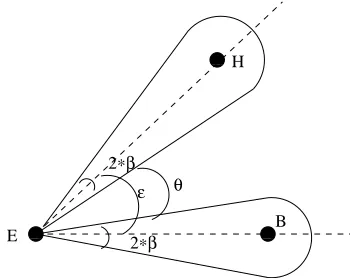
point we would like to mention that even if F was a little displaced and the line joining EF did not coincide exactly with the line joiningEB,E might still need to defer trans-mission toF in order to avoid interfering atB. Specifically, in Basic DMAC, node E defers transmission towardsF if the angle betweenEF andEB is less than some threshold, . We illustrate with the help of Figure 2. We assume that all nodes transmit with a beamwidth of 2βdegrees. Now if nodeE has overheard a RTS or CTS from node B, it up-dates the DNAV table with the direction DEB. Now if E
wants to send a packet to nodeH, then it must beamform in the direction of DEH to transmit the RTS. Node E checks whether, the angle betweenDEB andDEH is greater than a threshold , where is as following:
= 2β+θ
whereθis the angular separation of the edges of the two beamforms. If θ is negative then the two beamforms may overlap. For our simulations we have assumedθ to be zero.
6.
PROBLEMS WITH BASIC DMAC
In this section we discuss some channel access problems with Basic DMAC that may arise with other directional MAC protocols as well.
• Hidden terminal problems
The well-known hidden terminal problem in multi hop wireless networks can be resolved by the exchange of RTS/CTS control packets as in MACA [7] and 802.11. However, the RTS/CTS exchange assumes that these packets are transmitted omnidirectionally. Directional transmission of RTS/CTS introduces two new kinds of hidden terminals, discussed below.
(1) Hidden terminal due to asymmetry in gain:
Consider Figure 1. Assume that all nodes in this fig-ure are currently idle. Nodes in their idle state (Omni
mode) have a gain of Go. Now assume that node
B transmits a Directional RTS (DRTS) to node F, andF responds with a Directional CTS (DCTS). As-sume that nodeA (still inomni mode) is far enough from nodeF not to hear this DCTS. DATA transmis-sion begins from node B to F, both nodes pointing their transmission and reception beams with a gain
Gd. Node A cannot sense this transmission. While this communication is in progress, assume that node
Ahas a packet to send to nodeE. NodeAsenses the channel with a directional beam (of gainGd) pointed
towardsEand concludes that the channel is idle. Sub-sequently, it sends a DRTS to nodeE. However, since nodeF is receiving DATA with a gainGdwith a beam
pointed toward node B (and nodeA), it is very much possible that the DRTS fromAinterferes at nodeF. In other words, sender and receiver nodes with trans-mit and receive gain ofGd and Go respectively, may be out of each other’s range, but may be within range if they both transmit and receive with gainGd(note
thatGdis greater thanGo).
(2) Hidden terminal due to unheard RTS/CTS:
A E B
C D
G F
H
Figure 1: An example scenario
to D. While this transmission is in progress, node B
sends a RTS to nodeF. F responds with a CTS. Al-thoughEmay be within the transmission range ofF, it does not receive the CTS, since it is beamformed in the direction ofD. On receiving the CTS fromF,B
starts transmitting data to F. While communication betweenBandFis in progress, assume thatEfinishes transmitting toDand now wants to transmit toF (or any other node in the direction ofF). E’s DNAV ta-ble indicates that it is free to transmit towardsF and on performing physical carrier sense,E finds that the channel is idle. E transmits the RTS and a collision occurs at F (sinceF’s receiving beam is pointing in the direction of E). Such occasions may not arise in the case of omnidirectional transmissions. With omni-directional transmissions, nodeBmay be aware of the ongoing transmission from E. This would preventB
from transmitting the RTS whileEis engaged in com-munication. This clearly suggests a potential tradeoff between spatial reuse and collisions when using direc-tional antennas.
• Shape of Silenced Regions
Due to the higher gain of directional antennas, the shapes of thesilenced regionsare different for omnidi-rectional and diomnidi-rectional antennas. The impact of the shape of the silenced regions on the overall network performance is not straightforward, but it is indirectly dependent on the topology characteristics, traffic pat-terns and beamwidth of directional transmission.
• Deafness
Another drawback of directional beamforming is deaf-ness. We explain deafness using the scenario in Figure 1. Assume that both nodesC andD have packets to send to node B. Assume that both nodes C and D
choose the route through E to reach B. At a given time, if E is forwarding D’s packet, C would be un-aware of it (when using Basic DMAC) and may trans-mit a RTS meant forE. SinceEwould be beamformed in the direction ofB,E does not receive the RTS and consequently does not respond with a CTS. Node C, on receiving no response fromE, retransmits the RTS. This goes on until the RTS-retransmit limit has been reached. This amounts to excessive wastage of network capacity in unproductive control packet transmissions. Also, since C would increase its backoff interval on each attempt, this phenomenon can result in unfair-ness as well. We refer to this asdeafnesssince nodeE
is “deaf” to the signals from nodeCwhile it is beam-formed in the direction ofB.
0 0 0 1 1 1
0 0 0 1 1 1 0 0 0 1 1 1
2∗β
2∗β ε θ
E
H
B
Figure 2: An example where node E wishes to send a packet to H while it has a DNAV entry for direction
DEB. The figure shows a condition where node E
can safely transmit to node H, since it would not interfere with node B’s communication
7.
MULTI-HOP RTS MAC PROTOCOL
In this section, we propose a variation to Basic DMAC, called Multi-Hop RTS MAC (MMAC). While Basic DMAC was motivated by the possibility of higher spatial reuse, MMAC attempts to exploit the extended transmission range of directional antennas, while achieving spatial reuse compa-rable to the Basic DMAC protocol. Althoughdeafness and
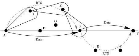
hidden terminalsproblems still exist in MMAC, better use of directional capabilities in MMAC can compensate for their negative impact, leading to improvement in performance as observed in later sections. To illustrate the benefit of uti-lizing extended transmission range, let us refer to Figure 3. Assume that all the nodes are idle (i.e., in theOmni mode). Also assume that ifAtransmits directionally, onlyB,Gand
Dwould be able to receive the signal while they are in their
Omni mode. However, a communication may directly take place betweenAandF, if bothAandF are pointing their beams towards each other. With the protocol below, such direct communication between nodesAandF is possible.
7.1
Protocol Description: Multi-Hop RTS
For describing the multi-hop RTS protocol, we define two kinds of neighbors: DO-neighborsandDD-neighbors.
• Direction-Omni (DO) Neighbor: A nodeB is a DO-neighbor of a nodeAif nodeBcan receive a directional transmission fromAeven ifB is in theOmnimode.
be noted that DD-neighbors are capable of single hop communication, since they can form a direct link be-tween them. Also note that, allDO-neighborsare also
DD-neighbors, but not necessarily vice versa.
In the above notation DO is an abbreviation for “Directional-Omni” and DD is an abbreviation for “Directional-Directional”. Following similar terminology, communication between DO-neighbors may be called DO-communication, and between DD-neighbors, DD-communication. In the scenario depicted in Figure 3, assume that nodeFis a DD-neighbor of nodeA
and nodeBis a DO-neighbor of nodeA. Similarly, nodeC
is a DO-neighbor of nodeB, and nodeF is a DO-neighbor of nodeC. ADO-neighbor routefromAtoF isA-B-C-F.
It is important to note that although two DD-neighbors can communicate with each other directly (provided they beamform in each other’s direction), some mechanism is needed to first make them beamform in each other’s direc-tion. This observation motivates the proposed Multi-Hop RTS MAC protocol. The Multi-Hop RTS MAC protocol (MMAC) builds on the Basic DMAC protocol. The MAC layer is supplied with aDO-neighbor route to the intended DD-neighbor (F in our example in Figure 3). We assume that a module running above the MAC layer is capable of deciding the suitableDO-neighbor routeto a DD-neighbor, and can specify the corresponding transceiver profiles to be used. The multi-hop RTS protocol has been designed as part of a larger ad hoc networking system that utilizes directional antennas [12]. Architecture of this system includes several modules such as neighbor discovery, link characterization, proactive routing, and a position information module. In-terested readers are referred to [12].
Once the MAC layer has received the packet with the route, the idea is to send a RTS along the DO-neighbor route to the DD-neighbor (destination), and request the destina-tion node (node F, in the example in Figure 3) to point its receiving beam towards the RTS sender (node A) at a spe-cific point of time in the near future. Node F receives the RTS, transmits the CTS in the direction of the RTS sender (node A) and waits for the arrival of the DATA packet. The details of this MMAC protocol are discussed below. For illustration purposes we will refer to Figure 3, where we as-sume that node A wishes to transmit a packet to node T. This is achieved by having node A transmit the data packet directly to node F, using MMAC. Node F, in turn, deliv-ers the packet to node T using MMAC as well, as shown in Figure 3.
7.2
Channel Reservation
The notion of reserving the channel before communication is retained in this protocol. In fact, the necessity for channel reservation becomes acute in MMAC. Setting up the direc-tional link between A and F involves multiple RTSs (to be forwarded) as well as requires node A to inactively wait for CTS during that time interval. This may be viewed as a sub-stantial investment of network resources that is worthwhile only if the subsequent CTS/DATA/ACK (transmitted using DD-communication) is successful. This motivates conserva-tive channel reservation so that once the directional link has been established, the DATA transmission may be carried out uninterrupted. The mechanism is described below.
G C
F A
B
D
T
R S
Data
Data
RTS RTS
Figure 3: A scenario showing how the multi-hop
RTS is forwarded from node A to node F
• RTS Transmission:
1. The MAC layer of node A receives a packet (from an upper layer) containing the DO-neighbor route to the next DD-neighbor, F. The route is specified as A-B-C-F. LetTB andTF be the transceiver profile of the DO-neighbor and the DD-neighbor. The transceiver profiles for nodes B and F are necessary for direc-tional RTS transmissions as detailed in the subsequent steps. These profiles are assumed to be maintained by a neighbor discovery module in our proposed system.
2. Upon receiving the packet, MMAC checks for the status of the physical layer. It proceeds to step 3 only when the physical layer is not engaged in transmitting or receiving packets.
3. MMAC at node A, now requests the physical layer to beamform according to the transceiver profileTF. Let us denote this beam byBF, since the beam points in the direction of node F.
DAD for the duration specified in the RTS packet. In
addition, D sets DNAV for the direction(DAD + 180 ) mod 360. The latter is necessary so that D does not initiate a communication in the direction of node F, before F has received the multi-hop RTS. Therefore, the duration for which transmission is deferred along the direction(DAD + 180 ) mod 360is equal to the
time required for the multi-hop RTS to reach F from A. This time is calculated by node D as theTime re-quired for 1 RTS transmission × Number of hops in the multi-hop route (note that theNumber of hops in the multi-hop routeis also included in the RTS packet, and theTime required for 1 RTS transmissionis con-stant as explained in the next step of this protocol).
Destination node F may receive the RTS from A in some instances. For example, this may occur if F hap-pens to be beamformed in the direction of A, when A initiates RTS transmission. If F receives this RTS, it may reply immediately with a CTS, or may optionally switch to the omni mode to be able to receive the im-minent multi-hop RTS (discussed in step 5). We use the former option in our simulations. When using this option, node A remains beamformed in the direction of F after transmitting the RTS. If node A receives a CTS from F, it initiates data transmission. If the CTS does not arrive within a suitable timeout interval (similar to Basic DMAC), node A proceeds to step 5.
5. MMAC now constructs a special type of RTS packet that is delivered to the destination over multiple hops (we call it theforwarding-RTS). This RTS packet con-tains theDO-neighbor routefrom node A to F (A-B-C-F in our example) and the duration field indicat-ing the duration of subsequent DATA/ACK transmis-sions. When all the steps (namely virtual and physical carrier sensing, backing off and waiting for DIFS in-terval) have been successfully performed, MMAC at node A transmits the forwarding-RTS packet to the DO-neighbor specified in the route (B in our exam-ple). None of the nodes (either on the DO-neighbor route or otherwise) modify their DNAV tables on re-ceiving or overhearing theforwarding-RTSpacket.
Nodes which receive the forwarding-RTS packet for-ward it to their DO-neighbor specified in the DO-neighbor route. The forwarding-RTS packet gets high-est priority for transmission (forwarding of RTS by the intermediate node does not involve backing off). This implies that theTime required for 1 RTS transmission
is a constant, known a priori. Now, if a node in the
DO-neighbor route is busy, or has a DNAV set for the direction of forwarding, it simply drops the RTS. The forwarding-RTS packets are not acknowledged on re-ceipt.
6. In the meantime, while the forwarding-RTS packet is being forwarded to node F, node A beamforms in the direction of F and waits in anticipation of the CTS. If the CTS does not come back within a CTS-timeout duration, then A goes back to step 3 and initiates re-transmission. The time for which A waits for the CTS
is calculated as the time required for the forwarding RTS packet to reach F (over the specified route) plus the turn-around time for F to send the CTS. Since in-termediate nodes do not backoff while forwarding RTS packets, the CTS timeout duration can be calculated accurately.
• RTS Reception and CTS Transmission:
On receiving the forwarding-RTS, node F replies with a CTS by pointing its transmitting beam in the di-rection of A. The transmission of the CTS must be preceded by virtual and physical carrier sensing, and waiting for a SIFS interval of time (as described pre-viously for the Basic DMAC protocol).
• CTS Reception and DATA/ACK Exchange:
Node A remains beamformed in the direction of F and would thus receive the CTS directionally. Once the CTS is received, the directional-directional link (DD-link) has been successfully formed and node A pro-ceeds to send the DATA packet using beamBF. If F receives the DATA packet successfully, it acknowledges node A with an ACK. The ACK is sent using the same beam used for sending the CTS. Nodes that overhear the CTS or DATA packet update their DNAV tables with the duration specified in the packets. The du-ration field of the CTS includes the time required for completing the subsequent exchange of data and ack packets. This time is obtained from the duration field specified in the RTS packets.
8.
PERFORMANCE EVALUATION
In this section we evaluate the performance of Basic DMAC as well as Multi-Hop RTS protocol. We compare both the protocols to the IEEE 802.11 standard. We discuss some results reflecting the pros and cons of directional commu-nication. For our simulations we have used the Qualnet Simulator, version 2.6.1 [16]. The directional gain for the antenna is 10 dB and the beamwidth used is 45 degrees. The approximate transmission range when using IEEE 802.11 is 250 meters. The approximate transmission range of a DD-linkis 900 meters. We use the two-raypropagation model. We do not consider node mobility in our simulation scenar-ios.
8.1
Simulation Results
Directional communication introduces three new problems; new kinds of hidden terminals, higher directional interfer-ence, and deafness (as discussed in Section VI). In this pa-per we intend to evaluate the net impact of directional an-tennas. The problems related to using directional antennas are dependent on topology; for instance, nodes placed in a straight line may suffer using directional antennas due to the higher directional interference. Performance also depends on the flow or route configuration in the system; for instance, if routes of two flows share a common link, then deafness
Per Flow Throughput (Kbps) IEEE 802.11 Basic DMAC Figure 4(a)
A to D 409.05 1106.76 B to E 379.92 628.82 C to F 400.76 968.60 Aggregate 1189.73 2704.18 Figure 4(b)
A to D 391.54 978.66 B to E 401.48 233.46 C to F 401.79 207.39 Aggregate 1194.81 1419.51
Table 1: Comparing per flow throughput of DMAC and 802.11
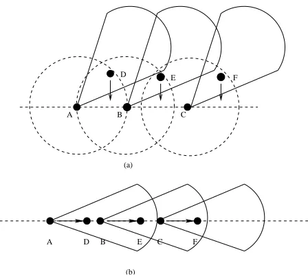
First, we show the dependence of performance on topol-ogy. Figure 4 depicts 6 nodes in two different configurations. Nodes A, B and C in Figure 4 are always backlogged with CBR traffic and packets of size 512 bytes. The transmitting beamforms of nodes A, B and C are shown. The destina-tions are nodes D, Eand F, respectively. We compare the performance of Basic DMAC (MMAC behaves identical to Basic DMAC in single hop communication) with 802.11, for both configurations.
In Table I, for the scenario from Figure 4(a), the total throughput of DMAC is more than twice of 802.11. This is because directional communication increases the spatial reuse of the channel. For the scenario in Figure 4(b), DMAC does not offer much benefit. Since the interfering range of directional antennas is larger, using DMAC, only one of the 3 transmissions can occur at any given time. Scenario in Figure 4(b) is also affected by the hidden terminal prob-lem. This happens because A neither receives F’s CTS to C, nor senses C’s DATA towards F (the hidden terminal problem due toasymmetry in gain). Observe that A would initiate directional transmission to D irrespective of whether C is communicating with F. Thus even though a collision happens at F, the packet from node A to D is transmitted successfully. This prevents thecontention windowof node A from growing exponentially. As a result of lesser backing off, node A achieves a high throughput compensating partially for the negative impact of higher directional interference. As evident from the individual flow throughputs, nodes B and C get a smaller fraction of the bandwidth while A consumes a much larger fraction. For 802.11, all the three flows share the channel almost equally. However, due to higher collision and backing off, it achieves slightly lesser throughput rela-tive to DMAC.
Random topologies would be characterized by lesser de-gree of node alignment, allowing higher scope for spatial reuse. Later in this section, we evaluate the performance on random topologies.
Routes taken by the flows also affect the performance of directional antenna protocols. Flows that share a common link cause deafness problems. To illustrate this, we per-formed simulations for an example scenario shown in Figure 5. Both nodes A and B wish to send packets to node D, via
A B C
F
D E
(a)
B E C F
D A
(b)
Figure 4: (a) A scenario allowing high spatial reuse for DMAC. (b) High directional interference and the hidden terminal problem degrade performance of DMAC
node C. Table II compares DMAC and 802.11 in terms of total throughput (as a function of the rate of CBR traffic). Results show that DMAC performs worse than 802.11. This degradation occurs due to deafness, as discussed earlier. It should be pointed out that 802.11 also suffers the problem of deafness, although less acutely. Consider Figure 5, but using 802.11 with omnidirectional antennas. Assume now that A is forwarding node X’s packet to C and B is forwarding node Y’s packet to C. Both packets are finally destined to reach D. Using 802.11, when C is transmitting to D, nodes A and B are aware of the communication and defer transmission.
0 0 1 1
00 00 00 11 11 11
0 0 1 1
0 0 1 1 0
0 0 1 1 1
0 0 1 1
00000000000 00000000000 00000000000 00000000000 11111111111 11111111111 11111111111 11111111111
000000000 000000000 000000000 000000000 000000000 000000000 000000000 000000000 000000000
111111111 111111111 111111111 111111111 111111111 111111111 111111111 111111111 111111111
A
B
C D
X
Y
Figure 5: An example to illustrate deafness
However, nodes X and Y may initiate RTSs to A and B respectively, to which they receive no response. X and Y would continue to send RTSs and backoff repeatedly. Thus the problem of deafness occurs two hop away from the com-municating link in 802.11 while in DMAC (and MMAC), it occurs in the one-hop region.
1 2 3 4 5
6 7 8 9 10
11 12 13 14 15
16 17 18 19 20
21 22 23 24 25
( a )
1 2 3 4 5
6 7 8 9 10
11 12 13 14 15
16 17 18 19 20
21 22 23 24 25
( b )
1 2 3 4 5
6 7 8 9 10
11 12 13 14 15
16 17 18 19 20
21 22 23 24 25
( c )
1 2 3 4 5
6 7 8 9 10
11 12 13 14 15
16 17 18 19 20
21 22 23 24 25
( d )
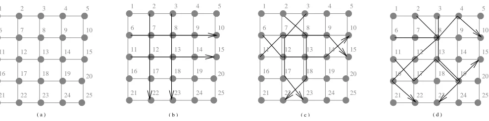
Figure 6: (a) The 5x5 grid topology used for simulations. (b) Flows with aligned routes (c) Less alignment in routes (d) Randomly chosen routes. We compare the performance of DMAC, MMAC and 802.11 for all the above scenarios. The grid distances, although shown to be identical, are varied over multiple simulations
Aggregate Throughput (Kbps) Traffic (per flow) IEEE 802.11 Basic DMAC
CBR 500 Kbps 403.91 299.47 CBR 1000 Kbps 409.34 290.47 CBR 1500 Kbps 409.38 290.47
Table 2: Evaluating the impact of “deafness”
using directional antennas, are forced to reach through mul-tiple hops since omnidirectional communication requires so. As discussed later, we have also performed some preliminary experiments comparing DMAC with MMAC, using routes that are feasible only with directional antennas.
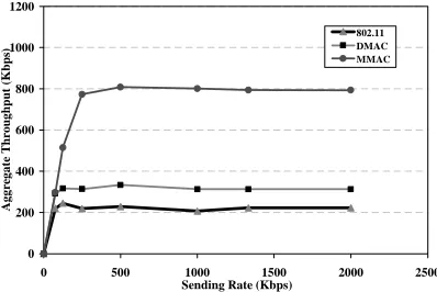
Figure 6(a) shows a grid topology of 25 nodes. We sys-tematically introduce flows into this grid and vary the traffic patterns. We begin with 4 multi hop flows as shown in Fig-ure 6(b). The distance between rows and columns in the grid, called grid-distance henceforth, is 150 meters. This ensures that adjacent, as well as diagonal nodes can com-municate with each other. Note that nodes 7, 9, 17 and 19 are considered diagonal to node 13. In our simulations, the multi-hop RTS is forwarded over not more than 3 hops and using the same route as shown in the figures. The traffic on each flow is CBR (Constant Bit Rate) and is varied from 75 Kbps to 2000 Kbps with packet size of 512 bytes. Figure 7 shows the comparative results of 802.11, DMAC and MMAC in terms of aggregate throughput over all flows. In Figure 7, DMAC performs worse than 802.11. The poor performance of DMAC may be attributed to the high “alignment” of hops in the chosen routes and to higher interference in directions of ongoing communication. MMAC performs better than both DMAC and 802.11. This is because DATA is trans-ferred over fewer hops using MMAC as opposed to 4 hops using DMAC/802.11. Therefore, the total consumption of the wireless bandwidth is much less, allowing greater num-ber of packets to be transmitted within the same span of time.
In the next experiment, we alter the routes. The new routes are less aligned as shown in Figure 6(c). Figure 8 shows the relative performance of 802.11, DMAC and
0 200 400 600 800 1000 1200
0 500 1000 1500 2000 2500
Sending Rate (Kbps)
A
ggr
egate
T
hr
oughput
(Kbps
) 802.11
DMAC MMAC
Figure 7: Aggregate throughput (Kbps) of the net-work with routes in Figure 6(b)
MMAC. Evident from the graph, directional antenna proto-cols perform much better than 802.11 because the potential for spatial reuse is greater for this scenario. To put it dif-ferently, two node pairs on the route of a given flow can now communicate simultaneously using directional anten-nas, e.g., node pairs (6, 12) and (13, 14). This is possi-ble because the direction in which the individual node pairs communicate are not same, unlike the scenario in Figure 6(b). The throughput curves saturate beyond a particular data sending rate, because the channel capacity gets fully utilized. The aggregate throughput is higher for directional protocols, because more links can simultaneously communi-cate. However, DMAC is marginally better than 802.11 be-cause deafness offsets the gains derived from spatial reuse. It is interesting to note that deafness does not affect the performance of MMAC as much, because nodes that for-ward RTSs in MMAC are engaged in communication for a very small amount of time (and are not silenced during the CTS/DATA/ACK exchange). In comparison, intermediate nodes in DMAC and 802.11 remain occupied for the entire span of CTS, DATA and ACK transmission.
0 200 400 600 800 1000 1200
0 500 1000 1500 2000 2500
Sending Rate (Kbps)
A
ggr
egate
T
hr
oughput
(Kbps
)
802.11 DMAC MMAC
Figure 8: Aggregate throughput (Kbps) of the net-work with routes in Figure 6(c)
0 200 400 600 800 1000 1200
0 500 1000 1500 2000 2500
Sending Rate (Kbps)
A
g
g
r
e
g
a
te
T
hr
o
u
g
hput
(K
bps
)
802.11 DMAC MMAC
Figure 9: Aggregate throughput (Kbps) of the net-work with routes in Figure 6(d)
for this experiment. The aggregate throughput achieved by MMAC is much higher than DMAC, which is, in turn, higher than 802.11. This supports our intuition that “unaligned” routes enhance spatial reuse of the wireless channel, and di-rectional communication would consequently benefit.
We now compare the performance of the three protocols simulated over 25 random topologies and route patterns. One of the 25 random topologies (shown in Figure 10) is obtained by displacing thexandycoordinates of the nodes in the grid by random distances, chosen from an interval of [−150, 150] meters. The flows are same as the four flows used for the scenario in Figure 6(d). Observe that, although the intermediate nodes in the respective routes are identical, the degree of link alignment is less, indicating the possibility of higher spatial reuse. The other random topologies, gen-erated by placing 25 nodes randomly in the bounded region, also exhibit similar characteristics. The simulation results have been averaged over all the scenarios and shown in Fig-ure 11. On an average, random topologies show a significant improvement in performance using MMAC as evident in Fig-ure 11.
Having illustrated the comparative performances of IEEE 802.11 and our directional protocols, we now focus on the comparison between DMAC and MMAC. As mentioned ear-lier, to compare the throughput of DMAC, MMAC and
1
3
5
6
7 9 10
11 12
14 15
16 20
21
22
23 24 25 2
17
19 4
8
13
18
Figure 10: An instance of a random topology with randomly selected routes
0 200 400 600 800 1000 1200
0 500 1000 1500 2000 2500
Sending Rate (Kbps)
Ag
g
re
g
a
te
T
hr
o
u
g
hput
(K
bps)
802.11 DMAC MMAC
Figure 11: Average aggregate throughput of
DMAC/MMAC over multiple simulations using random topologies and routes
802.11, we used identical routes in our previous simulations. However, this is unfair for protocols that use directional antennas because routes suitable for 802.11 may be sub-optimal for DMAC and MMAC. To compare the relative performance of DMAC and MMAC, we design the routes to contain longest possible links that can be formed by each of the protocols. To achieve this, we scaled up distance be-tween nodes in the random topologies by a factor of two. On these random topologies, we use the same set of flows and routes used previously. We observed from simulation results (not documented in this paper), that increasing distance between nodes improves throughput of both DMAC and MMAC, provided the network does not get disconnected. This improvement is an outcome of lesser contention and interference experienced by the communicating nodes in the network.
0 0.5 1 1.5 2
0 500 1000 1500 2000 2500
Sending Rate (Kbps)
A
vg.
En
d
-to-En
d
D
el
a
y
(s
)
DMAC MMAC
Figure 12: Average end-to-end delay of
DMAC/MMAC over multiple simulations using random topologies and flows
DMAC as well as MMAC. This behavior may be explained as follows. When the network load is low, the contention and queueing delay at each intermediate hop is small. As the network load increases, queue sizes grow, increasing in turn, the average end-to-end delay of delivered packets. The curves saturate when the queues get full (the delay is calcu-lated only over packets that are not dropped due to queue overflow). However, MMAC outperforms DMAC since it utilizes the longest possible links between node pairs. While data packets have to travel on each DO-link when using DMAC, MMAC requires only RTSs to travel on the DO-linksand data to be transmitted on the potentially longer
DD-links. This enables MMAC to use fewer hops in sev-eral instances. However, the higher failure probability in transmitting themulti-hop RTSpacket when using MMAC, increases the latency of packet delivery due to frequent time-outs and retransmissions. This partially offsets the advan-tage of utilizing DD-links when using MMAC. Therefore, the performance of MMAC (in terms of end-to-end delay) is only slightly better in comparison to DMAC.
9.
FUTURE WORK
We plan to work on the design of directional MAC proto-cols that incorporate transmit power control. We also plan to evaluate new protocols that rely less on the upper layers for beamforming information. One such protocol could re-place theomni modeoperation of DMAC and MMAC, by having idle nodes to continuously rotate its receiving beam over 360 degrees. In this case, a node willing to initiate communication transmits a pre-defined “tone” towards the intended neighbor for timeT, whereT is time required by an idle node to complete one full rotation. When the in-tended neighbor senses the pre-defined “tone”, it aborts ro-tating and continues to point its receiving beam towards the DoA of the “tone”, in anticipation of an RTS from the sender. The sender node can then transmit an RTS once it has transmitted the “tone” forTtime units, and the receiver replies with a CTS. This effectively establishes a DD-link, with minimal reliance on upper layers. Through information exchanged in the RTS/CTS packets, the required transmit power levels of DATA and ACK packets could be suitably calculated. This approach has its own disadvantages. We intend to pursue these and other ideas towards the design
of more efficient directional MAC protocols. In addition to directional MAC protocols, we are also interested in the im-pact of directional antennas on the performance of routing [14] and other higher layer protocols.
10.
CONCLUSION
This paper considers two medium access control proto-cols for ad hoc networks using directional antennas. The results show that the performance of the system improves in terms of aggregate throughput and end-to-end delay. We also notice that the performance of the system clearly de-pends on the topology and flow pattern in the network, more aligned topologies degrading the performance of direc-tional antenna protocols. The multi-hop RTS protocol can outperform 802.11 and DMAC, suggesting that it is benefi-cial to employ directional communication in shared wireless medium in multi-hop ad hoc networks.
11.
ACKNOWLEDGMENTS
We thank Mineo Takai, Pradeep Kyasanur, Gaurav Navlakha and the anonymous referees for their comments and helpful suggestions.
12.
REFERENCES
[1] C. Balanis et al.“Smart Antennas for Future Reconfigurable Wireless Communciation Networks”, Annual Report, April, 2000. Arizona State University, http://www.eas.asu.edu/
trc-comm/nsf/presentations/Annual Report.pdf. [2] S. Bandyopadhyay, K. Hausike, S. Horisawa and S.
Tawara,“An Adaptive MAC and Directional Routing Protocol for Ad Hoc Wireless Networks Using ESPAR Antenna”, ACM MobiHoc, October 2001.
[3] V. Bharghavan,“Performance Analysis of a Medium Access Protocol for Wireless Packet Networks”, IE E E Performance and Dependability Symposium, Raleigh, NC. August 1998.
[4] A. Chandra V. Gummalla and J. O. Limb,“Wireless Medium Access Control Protocols”, IE E E
Communications. Surveys and Tutorials, vol. 3, no. 2, Second Quarter 2000.
[5] P. Gupta and P. R. Kumar,“The Capacity of Wireless Networks”, IEEE Transactions on Information Theory, pp. 388-404, vol. IT-46, no. 2, March 2000.
[6] M. Horneffer and D. Plassmann, “Directed Antennas in Mobile Broadband Systems”, IEEE INFOCOM, pp. 704-712, April 1996.
[7] P. Karn,“MACA - A New Channel Access Method for Packet Radio”, 9th ARRL Computer Networking Conference, Ontario, Canada, 1990.
[8] Y.-B. Ko, V. Shankarkumar and N. H. Vaidya,
“Medium access control protocols using directional antennas in ad hoc networks”Proc. of the IEEE INFOCOM, March 2000.
[10] “Qualnet simulator version 2.6.1”, Scalable Network Technologies, www.scalable-networks.com.
[11] R. Ramanathan,“On the Performance of Ad Hoc Networks with Beamforming Antennas”, ACM MobiHoc, October 2001.
[12] J. Redi and R. Ramanathan,“Utilizing Directional Antennas for Ad Hoc Networks”, IEEE Milcom, 2002 (classified volume).
[13] R. Roy Choudhury, X. Yang and N. H. Vaidya,“Using Directional Antennas in Ad Hoc Networks”, Final Report submitted from Texas A&M University to BBN Technologies for work done through July 2001.
[14] R. Roy Choudhury and N. H. Vaidya,“Ad Hoc Routing Using Directional Antennas”, Technical Report, Coordinated Science Laborotary, University of Illinois at Urbana-Champaign, August 2002.
[15] E . Royer, S. J. Lee and C. Perkins,“The Effects of MAC Protocols on Ad Hoc Network Communication”, IEEE WCNC, Chicago, IL, September 2000.
[16] M. Sanchez, T. Giles, and J. Zander,“CSMA/CA with Beam Forming Antennas in Multi-hop Packet Radio”, Swedish Workshop on Wireless Ad Hoc Networks, Mar. 5-6, 2001.
[17] M. Takai, J. Martin, R. Bagrodia and A. Ren,
“Directional Virtual Carrier Sensing for Directional Antennas in Mobile Ad Hoc Networks”, ACM MobiHoc, June 2002.
[18] J. Ward and R. Crompton,“Improving the
performance of slotted ALOHA packet radio networks with adaptive arrays”, IEEE Transactions on
Communications, vol. 40, no. 11, pp 1716-1724, 1992. [19] T. S. Yum and K. W. Hung,“Design Algorithms for
Multihop Packet Radio Networks with Multiple Directional Antennas”, IEEE Transactions on Communications, vol. 40, no. 11 pp. 1716-1724, 1992. [20] J. Zander,“Slotted ALOHA multihop packet radio